2001 NISSAN X-TRAIL engine oil
[x] Cancel search: engine oilPage 1962 of 3833
CL-4
NOISE, VIBRATION, AND HARSHNESS (NVH) TROUBLESHOOTING
NOISE, VIBRATION, AND HARSHNESS (NVH) TROUBLESHOOTING
PFP:00003
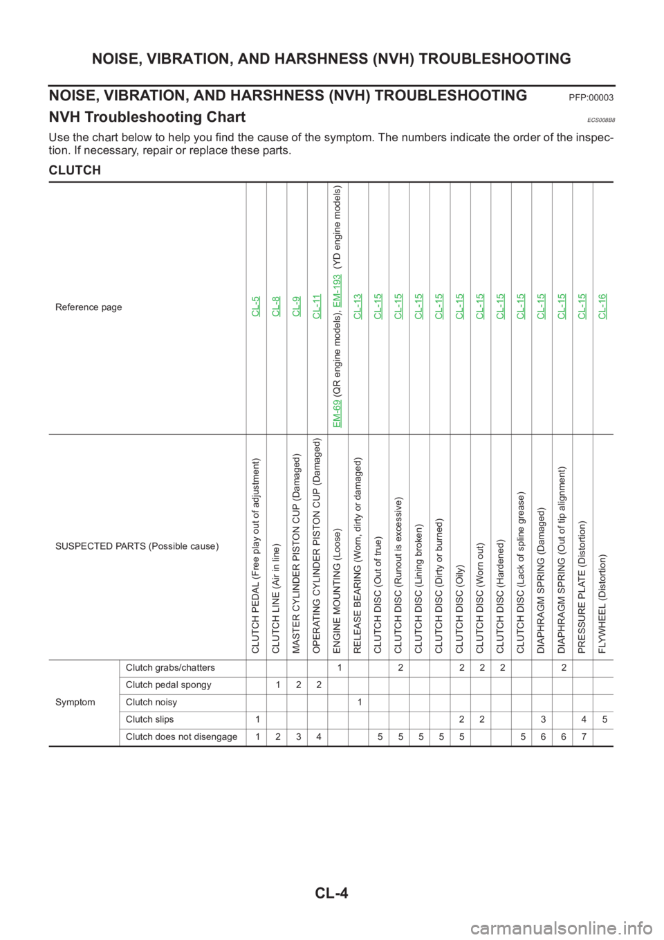
NVH Troubleshooting ChartECS008B8
Use the chart below to help you find the cause of the symptom. The numbers indicate the order of the inspec-
tion. If necessary, repair or replace these parts.
CLUTCH
Reference pageCL-5CL-8CL-9CL-11
EM-69
(QR engine models), EM-193
(YD engine models)
CL-13
CL-15CL-15CL-15CL-15CL-15CL-15CL-15CL-15CL-15CL-15CL-15CL-16
SUSPECTED PARTS (Possible cause)
CLUTCH PEDAL (Free play out of adjustment)
CLUTCH LINE (Air in line)
MASTER CYLINDER PISTON CUP (Damaged)
OPERATING CYLINDER PISTON CUP (Damaged)
ENGINE MOUNTING (Loose)
RELEASE BEARING (Worn, dirty or damaged)
CLUTCH DISC (Out of true)
CLUTCH DISC (Runout is excessive)
CLUTCH DISC (Lining broken)
CLUTCH DISC (Dirty or burned)
CLUTCH DISC (Oily)
CLUTCH DISC (Worn out)
CLUTCH DISC (Hardened)
CLUTCH DISC (Lack of spline grease)
DIAPHRAGM SPRING (Damaged)
DIAPHRAGM SPRING (Out of tip alignment)
PRESSURE PLATE (Distortion)
FLYWHEEL (Distortion)
SymptomClutch grabs/chatters 1 2 2 2 2 2
Clutch pedal spongy 1 2 2
Clutch noisy 1
Clutch slips 1 2 2 3 4 5
Clutch does not disengage 1 2 3 4 5 5 5 5 5 5 6 6 7
Page 1986 of 3833
MT-10
M/T OIL
M/T OIL
PFP:KLD20
Changing M/T OilECS008BR
DRAINING
1. Start the engine and let it run to warm up the transaxle.
2. Stop the engine. Remove drain plug and drain oil.
3. Set a gasket on the drain plug and install it to the transaxle.
CAUTION:
Do not reuse gasket.
FILLING
1. Remove filler plug. Fill with new oil until oil level reaches the specified limit near filler plug mounting hole.
2. After refilling oil, check oil level. Assemble gasket to filler plug, then install it to transaxle body.
CAUTION:
Do not reuse gasket.
Checking M/T OilECS008BS
OIL LEAKAGE AND OIL LEVEL
●Check that oil is not leaking from transaxle or around it.
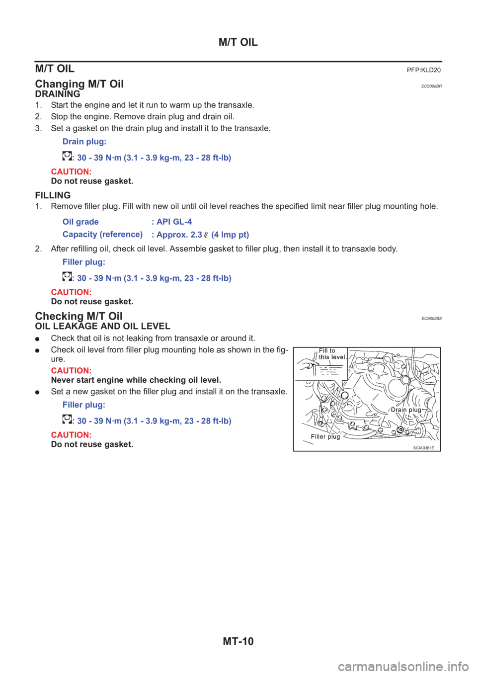
●Check oil level from filler plug mounting hole as shown in the fig-
ure.
CAUTION:
Never start engine while checking oil level.
●Set a new gasket on the filler plug and install it on the transaxle.
CAUTION:
Do not reuse gasket.Drain plug:
: 30 - 39 N·m (3.1 - 3.9 kg-m, 23 - 28 ft-lb)
Oil grade : API GL-4
Capacity (reference)
: Approx. 2.3 (4 lmp pt)
Filler plug:
: 30 - 39 N·m (3.1 - 3.9 kg-m, 23 - 28 ft-lb)
Filler plug:
: 30 - 39 N·m (3.1 - 3.9 kg-m, 23 - 28 ft-lb)
SCIA0361E
Page 1991 of 3833
TRANSAXLE ASSEMBLY
MT-15
D
E
F
G
H
I
J
K
L
MA
B
MT
TRANSAXLE ASSEMBLYPFP:32010
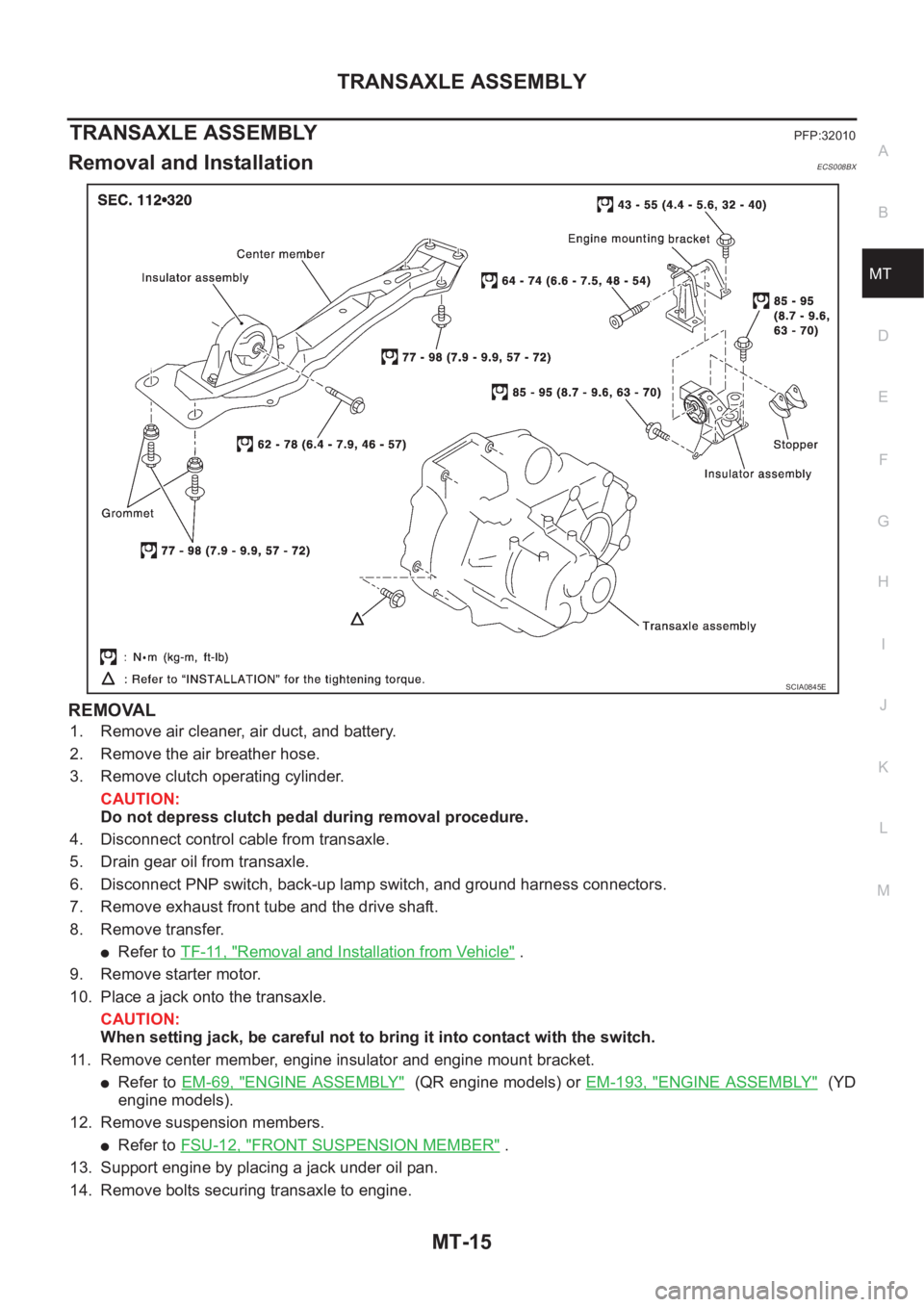
Removal and InstallationECS008BX
REMOVAL
1. Remove air cleaner, air duct, and battery.
2. Remove the air breather hose.
3. Remove clutch operating cylinder.
CAUTION:
Do not depress clutch pedal during removal procedure.
4. Disconnect control cable from transaxle.
5. Drain gear oil from transaxle.
6. Disconnect PNP switch, back-up lamp switch, and ground harness connectors.
7. Remove exhaust front tube and the drive shaft.
8. Remove transfer.
●Refer to TF-11, "Removal and Installation from Vehicle" .
9. Remove starter motor.
10. Place a jack onto the transaxle.
CAUTION:
When setting jack, be careful not to bring it into contact with the switch.
11. Remove center member, engine insulator and engine mount bracket.
●Refer to EM-69, "ENGINE ASSEMBLY" (QR engine models) or EM-193, "ENGINE ASSEMBLY" (YD
engine models).
12. Remove suspension members.
●Refer to FSU-12, "FRONT SUSPENSION MEMBER" .
13. Support engine by placing a jack under oil pan.
14. Remove bolts securing transaxle to engine.
SCIA0845E
Page 1992 of 3833
MT-16
TRANSAXLE ASSEMBLY
15. Remove transaxle from vehicle.
INSTALLATION
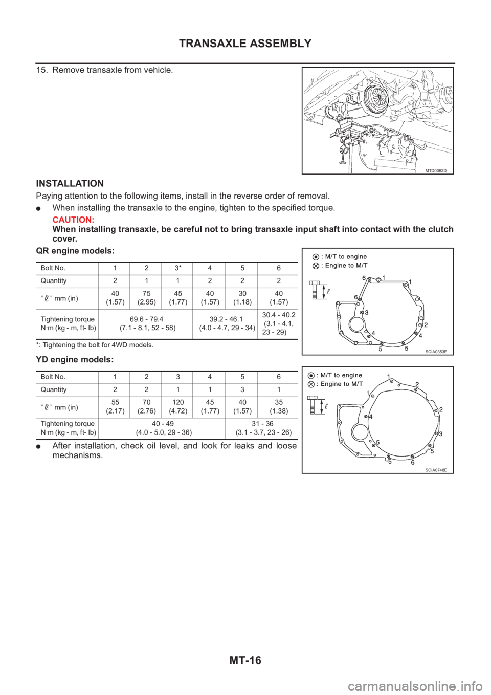
Paying attention to the following items, install in the reverse order of removal.
●When installing the transaxle to the engine, tighten to the specified torque.
CAUTION:
When installing transaxle, be careful not to bring transaxle input shaft into contact with the clutch
cover.
QR engine models:
*: Tightening the bolt for 4WD models.
YD engine models:
●After installation, check oil level, and look for leaks and loose
mechanisms.
MTD0062D
Bolt No. 1 2 3* 4 5 6
Quantity 2 1 1 2 2 2
“ ” mm (in)40
(1.57)75
(2.95)45
(1.77)40
(1.57)30
(1.18)40
(1.57)
Tightening torque
N·m (kg - m, ft- lb)69.6 - 79.4
(7.1 - 8.1, 52 - 58)39.2 - 46.1
(4.0 - 4.7, 29 - 34)30.4 - 40.2
(3.1 - 4.1,
23 - 29)
Bolt No. 1 2 3 4 5 6
Quantity 2 2 1 1 3 1
“ ” mm (in)55
(2.17)70
(2.76)120
(4.72)45
(1.77)40
(1.57)35
(1.38)
Tightening torque
N·m (kg - m, ft- lb)40 - 49
(4.0 - 5.0, 29 - 36)31 - 36
(3.1 - 3.7, 23 - 26)
SCIA0353E
SCIA0748E
Page 2073 of 3833
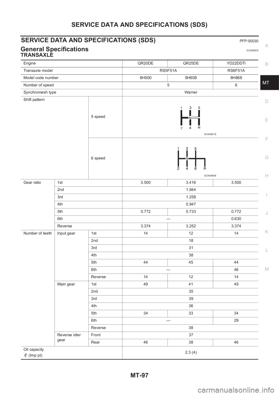
SERVICE DATA AND SPECIFICATIONS (SDS)
MT-97
D
E
F
G
H
I
J
K
L
MA
B
MT
SERVICE DATA AND SPECIFICATIONS (SDS)PFP:00030
General SpecificationsECS008CE
TRANSAXLE
Engine QR20DE QR25DE YD22DDTi
Transaxle model RS5F51A RS6F51A
Model code number 8H500 9H608 8H868
Number of speed 5 6
Synchromesh typeWarner
Shift pattern
5 speed
6 speed
Gear ratio 1st 3.500 3.416 3.500
2nd 1.944
3rd 1.258
4th 0.947
5th 0.772 0.733 0.772
6th — 0.630
Reverse 3.374 3.252 3.374
Number of teeth Input gear 1st 14 12 14
2nd 18
3rd 31
4th 38
5th 444544
6th — 46
Reverse 14 12 14
Main gear 1st 49 41 49
2nd 35
3rd 39
4th 36
5th 343334
6th — 29
Reverse 38
Reverse idler
gearFront 37
Rear 46 38 46
Oil capacity
(Imp pt)2.3 (4)
SCIA0821E
SCIA0955E
Page 2081 of 3833
AT-3
D
E
F
G
H
I
J
K
L
MA
B
AT TION ........................................................................ 287
Symptom Chart .................................................... 287
TCM Terminals and Reference Value ................... 306
CAN COMMUNICATION ........................................ 309
System Description .............................................. 309
TROUBLE DIAGNOSES FOR SYMPTOMS .......... 310
Wiring Diagram — AT — NONDTC ...................... 310
O/D OFF Indicator Lamp Does Not Come On ..... 312
Engine Cannot Be Started In “P” and “N” Position . 314
In “P” Position, Vehicle Moves Forward Or Back-
ward When Pushed .............................................. 315
In “N” Position, Vehicle Moves ............................. 315
Large Shock. “N” → “R” Position .......................... 317
Vehicle Does Not Creep Backward In “R” Position . 318
Vehicle Does Not Creep Forward In “D”, “2” Or “1”
Position ................................................................ 321
Vehicle Cannot Be Started From D
1 ..................... 323
A/T Does Not Shift: D
1→ D2 Or Does Not Kick down:
D
4→ D2 ............................................................... 326
A/T Does Not Shift: D
2→ D3 ............................... 328
A/T Does Not Shift: D
3→ D4 ............................... 330
A/T Does Not Perform Lock-up ............................ 332
A/T Does Not Hold Lock-up Condition ................. 333
Lock-up Is Not Released ...................................... 335
Engine Speed Does Not Return To Idle (Light Brak-
ing D
4→ D3 ) ....................................................... 336
Vehicle Does Not Start From D
1 ........................... 338
A/T Does Not Shift: D
4→ D3 , When Overdrive Con-
trol Switch “ON” → “OFF” ..................................... 339
A/T Does Not Shift: D
3→ 22 , W h e n S e l e c t o r L e v e r
“D”→ “2” Position ................................................ 340
A/T Does Not Shift: 2
2→ 11 , W h e n S e l e c t o r L e v e r
“2” → “1” Position ................................................. 341
Vehicle Does Not Decelerate By Engine Brake ... 343
TCM Self-diagnosis Does Not Activate ................ 344
ALL
MAIN POWER SUPPLY AND GROUND CIRCUIT . 350
Wiring Diagram — AT — MAIN ............................ 350
Diagnostic Procedure ........................................... 351
VEHICLE SPEED SENSOR·A/T (REVOLUTION
SENSOR) ................................................................ 353
Description ........................................................... 353
Wiring Diagram — AT — VSSA/T ........................ 355
Diagnostic Procedure ........................................... 356
DTC VEHICLE SPEED SENSOR MTR .................. 358
Description ........................................................... 358
Wiring Diagram — AT — VSSMTR ...................... 360
Diagnostic Procedure ........................................... 361
ACCELE RATOR PEDAL POSITION (APP) SEN-
SOR ........................................................................ 362
Description ........................................................... 362
Wiring Diagram — AT — TPS .............................. 364
Diagnostic Procedure ........................................... 365
SHIFT SOLENOID VALVE A .................................. 367
Description ........................................................... 367
Wiring Diagram — AT — SSV/A .......................... 369Diagnostic Procedure ...........................................370
Component Inspection ..........................................371
SHIFT SOLENOID VALVE B ..................................372
Description ............................................................372
Wiring Diagram — AT — SSV/B ...........................374
Diagnostic Procedure ...........................................375
Component Inspection ..........................................376
OVERRUN CLUTCH SOLENOID VALVE ...............377
Description ............................................................377
Wiring Diagram — AT — OVRCSV ......................378
Diagnostic Procedure ...........................................379
Component Inspection ..........................................380
TORQUE CONVERTER CLUTCH SOLENOID
VALVE .....................................................................381
Description ............................................................381
Wiring Diagram — AT — TCV ..............................383
Diagnostic Procedure ...........................................384
Component Inspection ..........................................385
BATT/FLUID TEMP SEN (A/T FLUID TEMP SEN-
SOR CIRCUIT AND TCM POWER SOURCE) .......386
Description ............................................................386
Wiring Diagram — AT — BA/FTS .........................388
Diagnostic Procedure ...........................................389
Component Inspection ..........................................391
ENGINE SPEED SIGNAL .......................................392
Description ............................................................392
Wiring Diagram — AT — ENGSS .........................393
Diagnostic Procedure ...........................................394
LINE PRESSURE SOLENOID VALVE ..................
.396
Description ............................................................396
Wiring Diagram — AT — LPSV ............................398
Diagnostic Procedure ...........................................399
Component Inspection ..........................................401
CAN COMMUNICATION LINE ...............................403
Description ............................................................403
On Board Diagnosis Logic ....................................403
Self-Diagnosis Code Confirmation Procedure ......403
Wiring Diagram — AT — CAN ..............................404
Diagnostic Procedure ...........................................405
A/T SHIFT LOCK SYSTEM ....................................406
Description ............................................................406
Shift Lock System Electrical Parts Location .........406
Wiring Diagram — SHIFT — ................................407
Diagnostic Procedure ...........................................408
KEY INTERLOCK CABLE ......................................412
Components .........................................................412
Removal ...............................................................412
Installation ............................................................413
ON-VEHICLE SERVICE ..........................................414
Control Valve Assembly and Accumulators ..........414
Control Cable Adjustment .....................................416
Park/Neutral Position (PNP) Switch Adjustment ..416
Differential Side Oil Seal Replacement ................417
Revolution Sensor Replacement ..........................417
REMOVAL AND INSTALLATION ...........................418
Removal ...............................................................418
Installation ............................................................419
OVERHAUL ............................................................421
Components .........................................................421
Page 2096 of 3833
AT-18
OVERALL SYSTEM
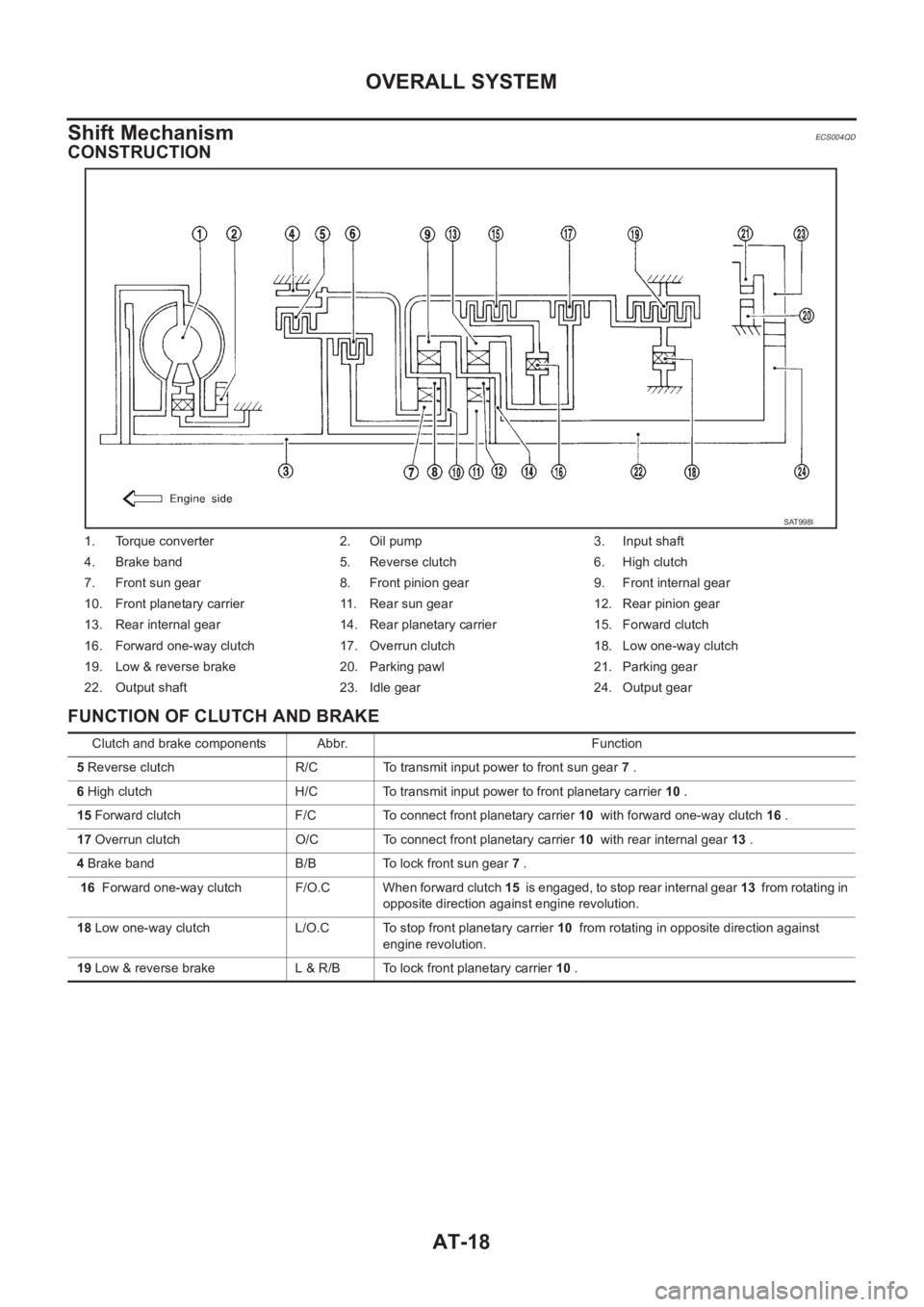
Shift Mechanism
ECS004QD
CONSTRUCTION
FUNCTION OF CLUTCH AND BRAKE
1. Torque converter 2. Oil pump 3. Input shaft
4. Brake band 5. Reverse clutch 6. High clutch
7. Front sun gear 8. Front pinion gear 9. Front internal gear
10. Front planetary carrier 11. Rear sun gear 12. Rear pinion gear
13. Rear internal gear 14. Rear planetary carrier 15. Forward clutch
16. Forward one-way clutch 17. Overrun clutch 18. Low one-way clutch
19. Low & reverse brake 20. Parking pawl 21. Parking gear
22. Output shaft 23. Idle gear 24. Output gear
SAT998I
Clutch and brake components Abbr. Function
5 Reverse clutch R/C To transmit input power to front sun gear 7 .
6 High clutch H/C To transmit input power to front planetary carrier 10 .
15 Forward clutch F/C To connect front planetary carrier 10 with forward one-way clutch 16 .
17 Overrun clutch O/C To connect front planetary carrier 10 with rear internal gear 13 .
4 Brake band B/B To lock front sun gear 7 .
16 Forward one-way clutch F/O.C When forward clutch 15 is engaged, to stop rear internal gear 13 from rotatin g in
opposite direction against engine revolution.
18 Low one-way clutch L/O.C To stop front planetary carrier 10 from rotating in opposite direction against
engine revolution.
19 Low & reverse brake L & R/B To lock front planetary carrier 10 .
Page 2097 of 3833
OVERALL SYSTEM
AT-19
D
E
F
G
H
I
J
K
L
MA
B
AT
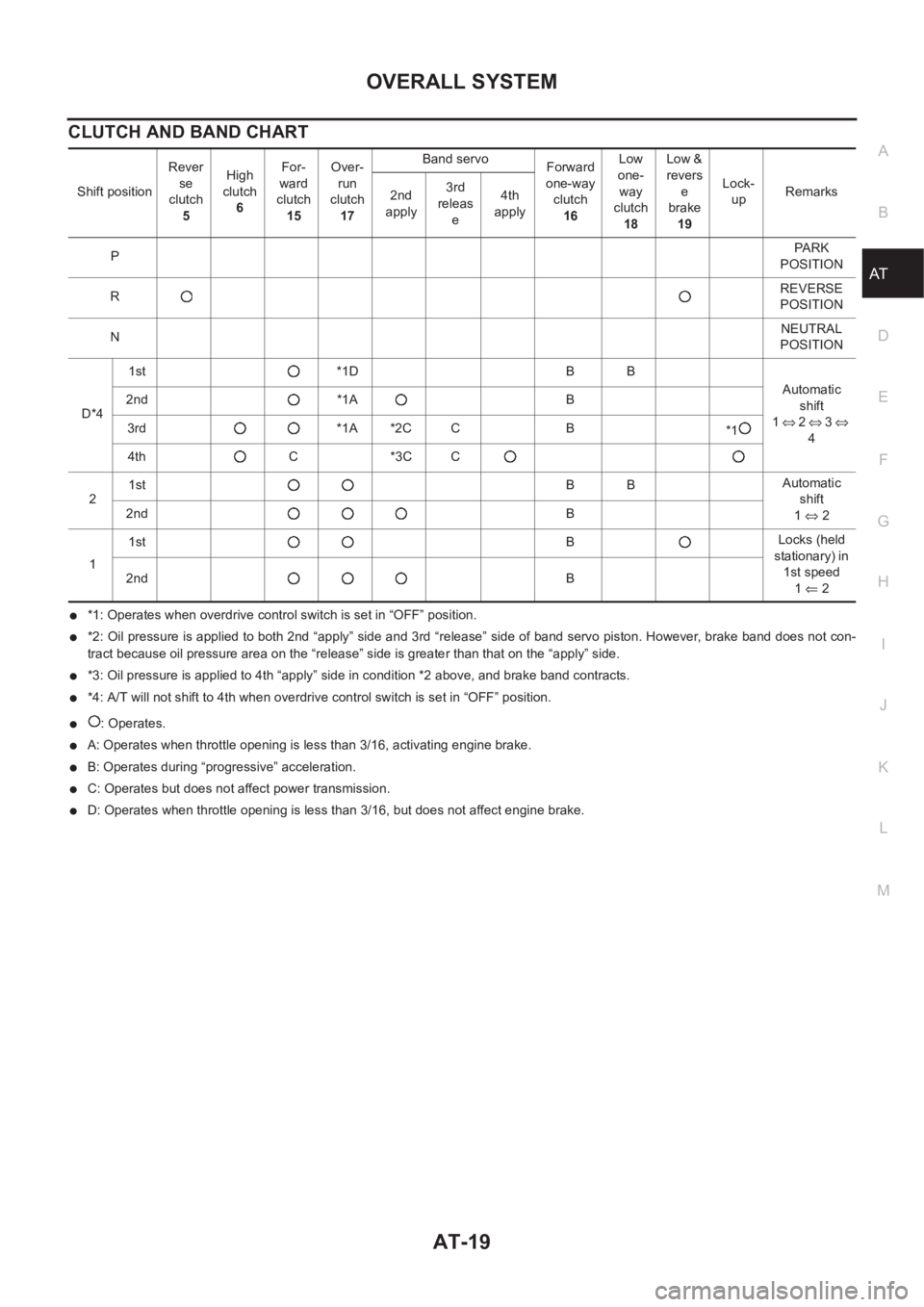
CLUTCH AND BAND CHART
●*1: Operates when overdrive control switch is set in “OFF” position.
●*2: Oil pressure is applied to both 2nd “apply” side and 3rd “release” side of band servo piston. However, brake band does not con-
tract because oil pressure area on the “release” side is greater than that on the “apply” side.
●*3: Oil pressure is applied to 4th “apply” side in condition *2 above, and brake band contracts.
●*4: A/T will not shift to 4th when overdrive control switch is set in “OFF” position.
●: Operates.
●A: Operates when throttle opening is less than 3/16, activating engine brake.
●B: Operates during “progressive” acceleration.
●C: Operates but does not affect power transmission.
●D: Operates when throttle opening is less than 3/16, but does not affect engine brake. Shift positionRever
se
clutch
5High
clutch
6For-
ward
clutch
15Over-
run
clutch
17Band servo
Forward
one-way
clutch
16Low
one-
way
clutch
18Low &
revers
e
brake
19Lock-
upRemarks
2nd
apply3rd
releas
e4th
apply
PPA R K
POSITION
RREVERSE
POSITION
NNEUTRAL
POSITION
D*41st *1D B B
Automatic
shift
1⇔ 2 ⇔ 3 ⇔
4 2nd *1A B
3rd *1A *2C C B
*1
4th C *3C C
21stBBAutomatic
shift
1⇔ 2 2ndB
11stBLocks (held
stationary) in
1st speed
1⇐ 2 2ndB