2001 NISSAN X-TRAIL weight
[x] Cancel search: weightPage 1945 of 3833
![NISSAN X-TRAIL 2001 Service Repair Manual FUEL TANK
FL-21
[YD22DDTi]
C
D
E
F
G
H
I
J
K
L
MA
FL
FUEL TANKPFP:17202
Removal and InstallationEBS00BL3
REMOVAL
WARNING:
Be sure to read “General Precautions” when working on fuel system. Refer t NISSAN X-TRAIL 2001 Service Repair Manual FUEL TANK
FL-21
[YD22DDTi]
C
D
E
F
G
H
I
J
K
L
MA
FL
FUEL TANKPFP:17202
Removal and InstallationEBS00BL3
REMOVAL
WARNING:
Be sure to read “General Precautions” when working on fuel system. Refer t](/manual-img/5/57405/w960_57405-1944.png)
FUEL TANK
FL-21
[YD22DDTi]
C
D
E
F
G
H
I
J
K
L
MA
FL
FUEL TANKPFP:17202
Removal and InstallationEBS00BL3
REMOVAL
WARNING:
Be sure to read “General Precautions” when working on fuel system. Refer to FL-14, "
General Precau-
tions" .
1. Disconnect battery ground cable.
2. Open the fuel filler cap and release the pressure inside the fuel
tank.
3. Remove rear seat bottom.
4. Peel off floor carpet, then remove inspection hole cover.
5. Disconnect the harness connector, fuel feed tube and fuel return
tube.
6. Drain fuel from fuel tank if necessary. For the draining proce-
dure, refer to step 4 in removal of FL-17, "
FUEL LEVEL SEN-
SOR UNIT" .
CAUTION:
For the safety work and to maintain fuel tank gravity at center, drain fuel to the level where fuel
tank weight at left and right becomes equal.
7. Disconnect the quick connector.
●Put mating marks on hoses for correct installation.
8. Remove exhaust center tube and insulator. Refer to EX-2, "
EXHAUST SYSTEM" .
9. Remove propeller shaft, Refer to PR-2, "
REAR PROPELLER SHAFT" .
SBIA0145E
1. Fuel filler cap 2. Grommet 3. Fuel filler tube
4. Vent hose 5. Vent tube 6. Fuel tank
7. Fuel filler hose 8. Fuel tank band 9. Fuel tank protector
SBIA0140E
Page 2085 of 3833

PRECAUTIONS
AT-7
D
E
F
G
H
I
J
K
L
MA
B
AT
●After performing each TROUBLE DIAGNOSIS, perform
“DTC (Diagnostic Trouble Code) CONFIRMATION PROCE-
DURE”.
The DTC should not be displayed in the “DTC CONFIRMA-
TION PROCEDURE” if the repair is completed.
●Before proceeding with disassembly, thoroughly clean the out-
side of the transaxle. It is important to prevent the internal parts
from becoming contaminated by dirt or other foreign matter.
●Disassembly should be done in a clean work area.
●Use lint-free cloth or towels for wiping parts clean. Common
shop rags can leave fibers that could interfere with the operation
of the transaxle.
●Place disassembled parts in order for easier and proper assembly.
●All parts should be carefully cleaned with a general purpose, non-flammable solvent before inspection or
reassembly.
●Gaskets, seals and O-rings should be replaced any time the transaxle is disassembled.
●It is very important to perform functional tests whenever they are indicated.
●The valve body contains precision parts and requires extreme care when parts are removed and serviced.
Place disassembled valve body parts in order for easier and proper assembly. Care will also prevent
springs and small parts from becoming scattered or lost.
●Properly installed valves, sleeves, plugs, etc. will slide along bores in valve body under their own weight.
●Before assembly, apply a coat of recommended ATF to all parts. Apply petroleum jelly to protect O-rings
and seals, or hold bearings and washers in place during assembly. Do not use grease.
●Extreme care should be taken to avoid damage to O-rings, seals and gaskets when assembling.
●After overhaul, refill the transaxle with new ATF.
●When the A/T drain plug is removed, only some of the fluid is drained. Old A/T fluid will remain in torque
converter and ATF cooling system.
Always follow the procedures under “Changing A/T Fluid” in the AT section when changing A/T fluid. Refer
to “Changing A/T Fluid”, AT-13, "
A/T FLUID" .
Service Notice or PrecautionsECS004Q3
FA I L - S A F E
The TCM has an electronic Fail-Safe (limp home mode). This allows the vehicle to be driven even if a major
electrical input/output device circuit is damaged.
Under Fail-Safe, the vehicle always runs in third gear, even with a shift lever position of “1”, “2” or “D”. The cus-
tomer may complain of sluggish or poor acceleration.
When the ignition key is turned “ON” following Fail-Safe operation, O/D OFF indicator lamp blinks for about 8
seconds. Refer to AT- 2 5 3 , "
SELF-DIAGNOSTIC PROCEDURE (WITHOUT CONSULT-II)" (EXCEPT FOR
EURO-OBD) or AT-51, "
TCM SELF-DIAGNOSTIC PROCEDURE (NO TOOLS)" (EURO-OBD).
The blinking of the O/D OFF indicator lamp for about 8 seconds will appear only once and be cleared. The
customer may resume normal driving conditions.
Always follow the “WORK FLOW”, refer to AT-262, "
Work Flow" (EXCEPT FOR Euro-OBD) or AT- 6 0 , "Work
Flow" (Euro-OBD).
The SELF-DIAGNOSIS results will be as follows:
●The first SELF-DIAGNOSIS will indicate damage to the vehicle speed sensor or the revolution sensor.
●During the next SELF-DIAGNOSIS, performed after checking the sensor, no damages will be indicated.
TORQUE CONVERTER SERVICE
The torque converter should be replaced under any of the following conditions:
●External leaks in the hub weld area.
●Converter hub is scored or damaged.
●Converter pilot is broken, damaged or fits poorly into crankshaft.
●Steel particles are found after flushing the cooler and cooler lines.
●Pump is damaged or steel particles are found in the converter.
●Vehicle has TCC shudder and/or no TCC apply. Replace only after all hydraulic and electrical diagnoses
have been made. (Converter clutch material may be glazed.)
SAT652J
Page 2213 of 3833
![NISSAN X-TRAIL 2001 Service Repair Manual DTC P0731 A/T 1ST GEAR FUNCTION
AT-135
[EURO-OBD]
D
E
F
G
H
I
J
K
L
MA
B
AT
Diagnostic ProcedureECS004RC
1.CHECK SHIFT SOLENOID VALVE
1. Remove control valve assembly. Refer to AT- 4 1 4 , "
Con NISSAN X-TRAIL 2001 Service Repair Manual DTC P0731 A/T 1ST GEAR FUNCTION
AT-135
[EURO-OBD]
D
E
F
G
H
I
J
K
L
MA
B
AT
Diagnostic ProcedureECS004RC
1.CHECK SHIFT SOLENOID VALVE
1. Remove control valve assembly. Refer to AT- 4 1 4 , "
Con](/manual-img/5/57405/w960_57405-2212.png)
DTC P0731 A/T 1ST GEAR FUNCTION
AT-135
[EURO-OBD]
D
E
F
G
H
I
J
K
L
MA
B
AT
Diagnostic ProcedureECS004RC
1.CHECK SHIFT SOLENOID VALVE
1. Remove control valve assembly. Refer to AT- 4 1 4 , "
Control Valve Assembly and Accumulators"
2. Check shift solenoid valve operation.
●Shift solenoid valve A
●Shift solenoid valve B
Refer to AT-136, "
Component Inspection" .
OK or NG
OK >> GO TO 2.
NG >> Repair or replace shift solenoid valve assembly.
2.CHECK CONTROL VALVE
1. Disassemble control valve assembly. Refer to AT-448, "
Control Valve Assembly" .
2. Check to ensure that:
●Valve, sleeve and plug slide along valve bore under their own weight.
●Valve, sleeve and plug are free from burrs, dents and scratches.
●Control valve springs are free from damage, deformation and fatigue.
●Hydraulic line is free from obstacles.
OK or NG
OK >> GO TO 3.
NG >> Repair control valve assembly.
3.CHECK DTC
Perform Diagnostic Trouble Code (DTC) confirmation procedure. Refer to AT- 1 3 2 , "
DIAGNOSTIC TROUBLE
CODE (DTC) CONFIRMATION PROCEDURE" .
OK or NG
OK >>INSPECTION END
NG >> Check transaxle inner parts (clutch, brake, etc.).
SCIA0755E
SAT367H
Page 2219 of 3833
![NISSAN X-TRAIL 2001 Service Repair Manual DTC P0732 A/T 2ND GEAR FUNCTION
AT-141
[EURO-OBD]
D
E
F
G
H
I
J
K
L
MA
B
AT
Diagnostic ProcedureECS004RG
1.CHECK SHIFT SOLENOID VALVE
1. Remove control valve assembly. Refer to AT- 4 1 4 , "
REM NISSAN X-TRAIL 2001 Service Repair Manual DTC P0732 A/T 2ND GEAR FUNCTION
AT-141
[EURO-OBD]
D
E
F
G
H
I
J
K
L
MA
B
AT
Diagnostic ProcedureECS004RG
1.CHECK SHIFT SOLENOID VALVE
1. Remove control valve assembly. Refer to AT- 4 1 4 , "
REM](/manual-img/5/57405/w960_57405-2218.png)
DTC P0732 A/T 2ND GEAR FUNCTION
AT-141
[EURO-OBD]
D
E
F
G
H
I
J
K
L
MA
B
AT
Diagnostic ProcedureECS004RG
1.CHECK SHIFT SOLENOID VALVE
1. Remove control valve assembly. Refer to AT- 4 1 4 , "
REMOVAL" .
2. Check shift solenoid valve operation.
●Shift solenoid valve B
Refer to AT-142, "
Component Inspection" .
OK or NG
OK >> GO TO 2.
NG >> Repair or replace shift solenoid valve assembly.
2.CHECK CONTROL VALVE
1. Disassemble control valve assembly. Refer to AT-448, "
Control Valve Assembly" .
2. Check to ensure that:
●Valve, sleeve and plug slide along valve bore under their own weight.
●Valve, sleeve and plug are free from burrs, dents and scratches.
●Control valve springs are free from damage, deformation and fatigue.
●Hydraulic line is free from obstacles.
OK or NG
OK >> GO TO 3.
NG >> Repair control valve assembly.
3.CHECK DTC
Perform Diagnostic Trouble Code (DTC) confirmation procedure. Refer to AT- 1 3 8 , "
DIAGNOSTIC TROUBLE
CODE (DTC) CONFIRMATION PROCEDURE" .
OK or NG
OK >>INSPECTION END
NG >> Check transaxle inner parts (clutch, brake, etc.).
SCIA0758E
SAT367H
Page 2225 of 3833
![NISSAN X-TRAIL 2001 Service Repair Manual DTC P0733 A/T 3RD GEAR FUNCTION
AT-147
[EURO-OBD]
D
E
F
G
H
I
J
K
L
MA
B
AT
Diagnostic ProcedureECS004RK
1.CHECK SHIFT SOLENOID VALVE
1. Remove control valve assembly. Refer to AT- 4 1 4 , "
REM NISSAN X-TRAIL 2001 Service Repair Manual DTC P0733 A/T 3RD GEAR FUNCTION
AT-147
[EURO-OBD]
D
E
F
G
H
I
J
K
L
MA
B
AT
Diagnostic ProcedureECS004RK
1.CHECK SHIFT SOLENOID VALVE
1. Remove control valve assembly. Refer to AT- 4 1 4 , "
REM](/manual-img/5/57405/w960_57405-2224.png)
DTC P0733 A/T 3RD GEAR FUNCTION
AT-147
[EURO-OBD]
D
E
F
G
H
I
J
K
L
MA
B
AT
Diagnostic ProcedureECS004RK
1.CHECK SHIFT SOLENOID VALVE
1. Remove control valve assembly. Refer to AT- 4 1 4 , "
REMOVAL" .
2. Check shift solenoid valve operation.
●Shift solenoid valve A
Refer to “Component Inspection” below.
OK or NG
OK >> GO TO 2.
NG >> Repair or replace shift solenoid valve assembly.
2.CHECK CONTROL VALVE
1. Disassemble control valve assembly. Refer to AT-448, "
Control Valve Assembly" .
2. Check to ensure that:
●Valve, sleeve and plug slide along valve bore under their own weight.
●Valve, sleeve and plug are free from burrs, dents and scratches.
●Control valve springs are free from damage, deformation and fatigue.
●Hydraulic line is free from obstacles.
OK or NG
OK >> GO TO 3.
NG >> Repair control valve assembly.
3.CHECK DTC
Perform Diagnostic Trouble Code (DTC) confirmation procedure. Refer to AT- 1 4 3 , "
DTC P0733 A/T 3RD
GEAR FUNCTION" .
OK or NG
OK >>INSPECTION END
NG >> Check transaxle inner parts (clutch, brake, etc.).
SCIA0722E
SAT367H
Page 2232 of 3833
![NISSAN X-TRAIL 2001 Service Repair Manual AT-154
[EURO-OBD]
DTC P0734 A/T 4TH GEAR FUNCTION
4. CHECK CONTROL VALVE
1. Disassemble control valve assembly.
Refer to AT- 4 4 8 , "
Control Valve Assembly" .
2. Check to ensure that:
●V NISSAN X-TRAIL 2001 Service Repair Manual AT-154
[EURO-OBD]
DTC P0734 A/T 4TH GEAR FUNCTION
4. CHECK CONTROL VALVE
1. Disassemble control valve assembly.
Refer to AT- 4 4 8 , "
Control Valve Assembly" .
2. Check to ensure that:
●V](/manual-img/5/57405/w960_57405-2231.png)
AT-154
[EURO-OBD]
DTC P0734 A/T 4TH GEAR FUNCTION
4. CHECK CONTROL VALVE
1. Disassemble control valve assembly.
Refer to AT- 4 4 8 , "
Control Valve Assembly" .
2. Check to ensure that:
●Valve, sleeve and plug slide along valve bore under their own weight.
●Valve, sleeve and plug are free from burrs, dents and scratches.
●Control valve springs are free from damage, deformation and fatigue.
●Hydraulic line is free from obstacles.
OK or NG
OK >> GO TO 5.
NG >> Repair control valve.
5. CHECK SHIFT UP (D3 TO D4 )
Does A/T shift from D
3 to D4 at the specified speed?
OK or NG
OK >> GO TO 9.
NG >> Check transaxle inner parts (clutch, brake, etc.).
6. CHECK LINE PRESSURE SOLENOID VALVE
1. Remove control valve assembly.
Refer to AT- 4 1 4 , "
REMOVAL" .
2. Refer to AT- 1 5 6 , "
Component Inspection" .
OK or NG
OK >> GO TO 7.
NG >> Replace solenoid valve assembly.
SCIA0745E
Page 2735 of 3833

WT-1
ROAD WHEELS & TYRES
E SUSPENSION
CONTENTS
C
D
F
G
H
I
J
K
L
M
SECTION
A
B
WT
ROAD WHEELS & TYRES
NOISE, VIBRATION, AND HARSHNESS (NVH)
TROUBLESHOOTING ................................................ 2
NVH Troubleshooting Chart ..................................... 2
ROAD WHEEL ............................................................ 3
Inspection ................................................................. 3
ALUMINUM WHEEL ............................................. 3
STEEL WHEEL ..................................................... 3ROAD WHEEL TIRE ASSEMBLY .............................. 4
Balancing Wheels (Bonding Weight Type) ............... 4
REMOVAL ............................................................. 4
WHEEL BALANCE ADJUSTMENT ....................... 4
Rotation .................................................................... 5
SERVICE DATA AND SPECIFICATIONS (SDS) ........ 6
Road Wheel .............................................................. 6
Page 2738 of 3833

WT-4
ROAD WHEEL TIRE ASSEMBLY
ROAD WHEEL TIRE ASSEMBLY
PFP:40300
Balancing Wheels (Bonding Weight Type)EES000QZ
REMOVAL
1. Remove inner and outer balance weights from the road wheel.
CAUTION:
Be careful not to scratch the road wheel during removal.
2. Using releasing agent, remove double-faced adhesive tape from the road wheel.
CAUTION:
●Be careful not to scratch the road wheel during removal.
●After removing double-faced adhesive tape, wipe clean traces of releasing agent from the road
wheel.
WHEEL BALANCE ADJUSTMENT
●If a tire balance machine has adhesion balance weight mode settings and drive-in weight mode setting,
select and adjust a drive-in weight mode suitable for road wheels.
1. Set road wheel on wheel balancer using the center hole as a guide. Start the tire balance machine.
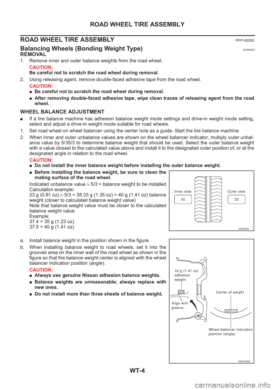
2. When inner and outer unbalance values are shown on the wheel balancer indicator, multiply outer unbal-
ance value by 5/35/3 to determine balance weight that should be used. Select the outer balance weight
with a value closest to the calculated value above and install it to the designated outer position of, or at the
designated angle in relation to the road wheel.
CAUTION:
●Do not install the inner balance weight before installing the outer balance weight.
●Before installing the balance weight, be sure to clean the
mating surface of the road wheel.
Indicated unbalance value × 5/3 = balance weight to be installed
Calculation example:
23 g (0.81 oz) × 5/3 = 38.33 g (1.35 oz) = 40 g (1.41 oz) balance
weight (closer to calculated balance weight value)
Note that balance weight value must be closer to the calculated
balance weight value.
Example:
37.4 = 35 g (1.23 oz)
37.5 = 40 g (1.41 oz)
a. Install balance weight in the position shown in the figure.
b. When installing balance weight to road wheels, set it into the
grooved area on the inner wall of the road wheel as shown in the
figure so that the balance weight center is aligned with the wheel
balancer indication position (angle).
CAUTION:
●Always use genuine Nissan adhesion balance weights.
●Balance weights are unreasonable; always replace with
new ones.
●Do not install more than three sheets of balance weight.
SMA054D
SEIA0166E