2001 NISSAN X-TRAIL seats
[x] Cancel search: seatsPage 2637 of 3833
TRANSFER ASSEMBLY
TF-27
C
E
F
G
H
I
J
K
L
MA
B
TF
Adapter case
1. Select the adjusting shim on the gear ring bearing.
●TF-23, "SELECTIONG ADJUSTING SHIMS".
2. Install the oil gutter.
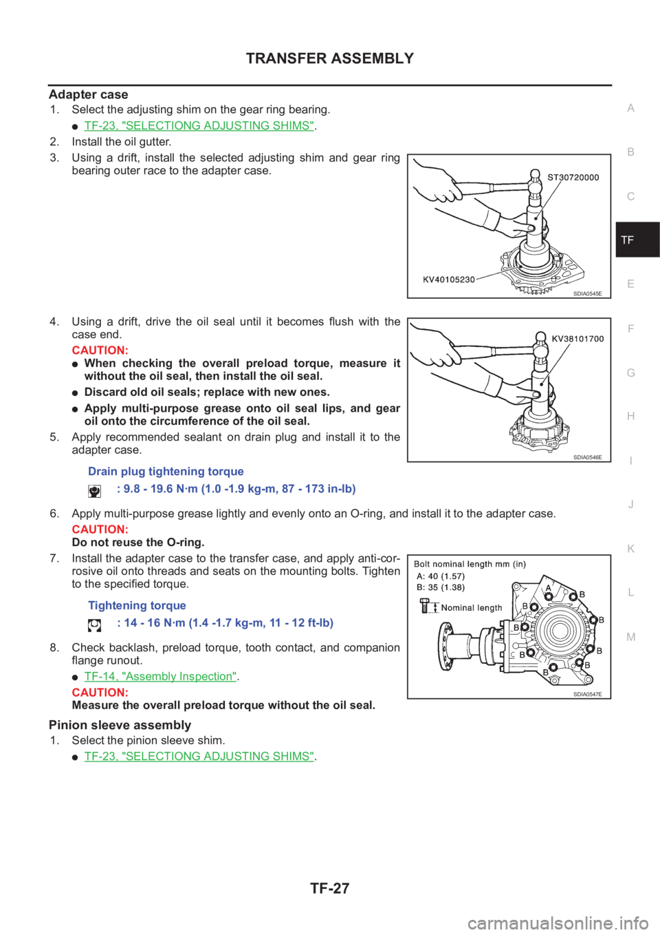
3. Using a drift, install the selected adjusting shim and gear ring
bearing outer race to the adapter case.
4. Using a drift, drive the oil seal until it becomes flush with the
case end.
CAUTION:
●When checking the overall preload torque, measure it
without the oil seal, then install the oil seal.
●Discard old oil seals; replace with new ones.
●Apply multi-purpose grease onto oil seal lips, and gear
oil onto the circumference of the oil seal.
5. Apply recommended sealant on drain plug and install it to the
adapter case.
6. Apply multi-purpose grease lightly and evenly onto an O-ring, and install it to the adapter case.
CAUTION:
Do not reuse the O-ring.
7. Install the adapter case to the transfer case, and apply anti-cor-
rosive oil onto threads and seats on the mounting bolts. Tighten
to the specified torque.
8. Check backlash, preload torque, tooth contact, and companion
flange runout.
●TF-14, "Assembly Inspection".
CAUTION:
Measure the overall preload torque without the oil seal.
Pinion sleeve assembly
1. Select the pinion sleeve shim.
●TF-23, "SELECTIONG ADJUSTING SHIMS".
SDIA0545E
Drain plug tightening torque
: 9.8 - 19.6 N·m (1.0 -1.9 kg-m, 87 - 173 in-lb)
Tightening torque
: 14 - 16 N·m (1.4 -1.7 kg-m, 11 - 12 ft-lb)
SDIA0546E
SDIA0547E
Page 2639 of 3833
TRANSFER ASSEMBLY
TF-29
C
E
F
G
H
I
J
K
L
MA
B
TF
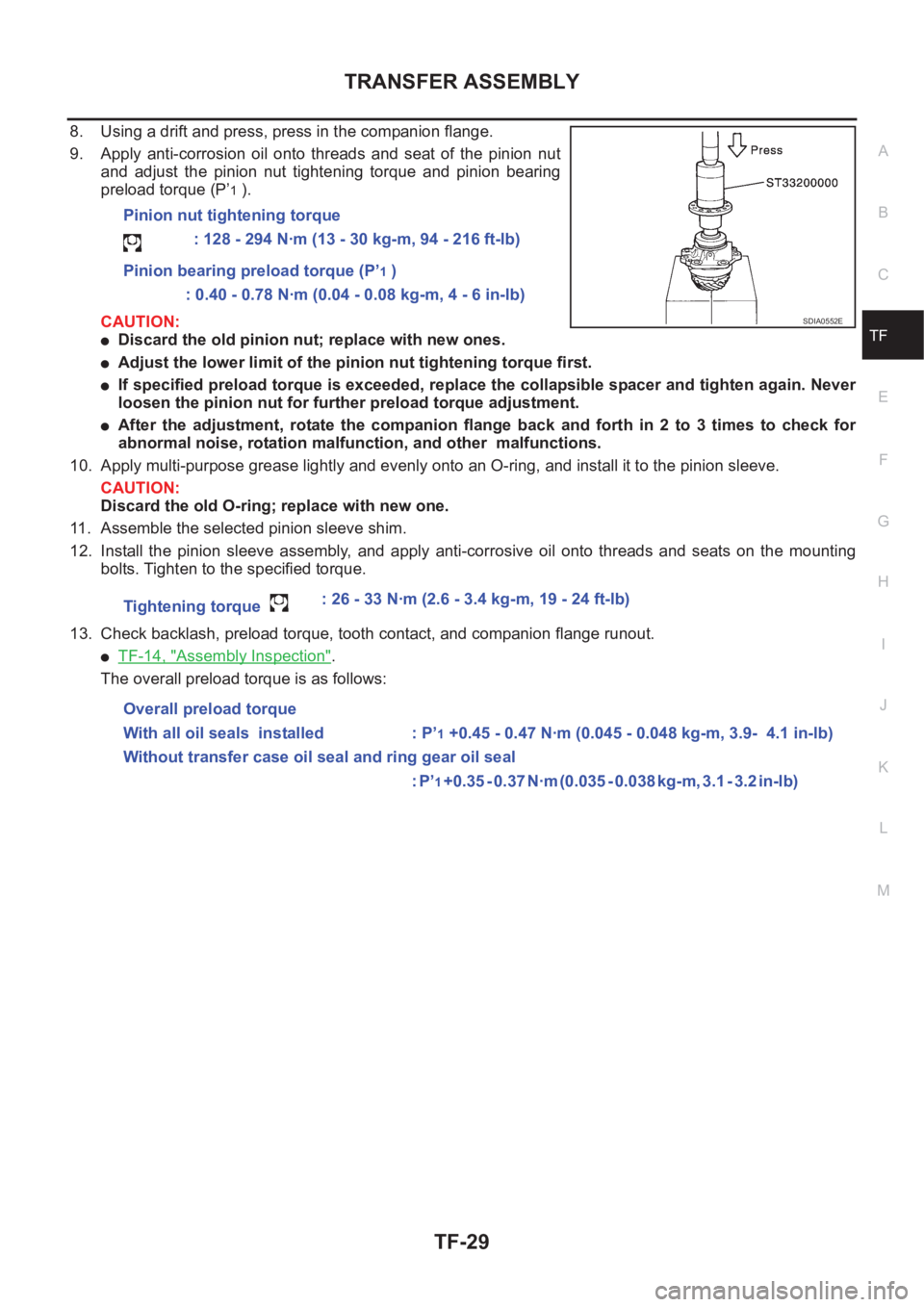
8. Using a drift and press, press in the companion flange.
9. Apply anti-corrosion oil onto threads and seat of the pinion nut
and adjust the pinion nut tightening torque and pinion bearing
preload torque (P’
1 ).
CAUTION:
●Discard the old pinion nut; replace with new ones.
●Adjust the lower limit of the pinion nut tightening torque first.
●If specified preload torque is exceeded, replace the collapsible spacer and tighten again. Never
loosen the pinion nut for further preload torque adjustment.
●After the adjustment, rotate the companion flange back and forth in 2 to 3 times to check for
abnormal noise, rotation malfunction, and other malfunctions.
10. Apply multi-purpose grease lightly and evenly onto an O-ring, and install it to the pinion sleeve.
CAUTION:
Discard the old O-ring; replace with new one.
11. Assemble the selected pinion sleeve shim.
12. Install the pinion sleeve assembly, and apply anti-corrosive oil onto threads and seats on the mounting
bolts. Tighten to the specified torque.
13. Check backlash, preload torque, tooth contact, and companion flange runout.
●TF-14, "Assembly Inspection".
The overall preload torque is as follows:Pinion nut tightening torque
: 128 - 294 N·m (13 - 30 kg-m, 94 - 216 ft-lb)
Pinion bearing preload torque (P’
1 )
: 0.40 - 0.78 N·m (0.04 - 0.08 kg-m, 4 - 6 in-lb)
Tightening torque : 26 - 33 N·m (2.6 - 3.4 kg-m, 19 - 24 ft-lb)
Overall preload torque
With all oil seals installed : P’
1 +0.45 - 0.47 N·m (0.045 - 0.048 kg-m, 3.9- 4.1 in-lb)
Without transfer case oil seal and ring gear oil seal
: P’
1 + 0 . 3 5 - 0 . 3 7 N · m ( 0 . 0 3 5 - 0 . 0 3 8 k g - m , 3 . 1 - 3 . 2 i n - l b )
SDIA0552E
Page 2714 of 3833
FSU-8
COIL SPRING AND SHOCK ABSORBER
COIL SPRING AND SHOCK ABSORBER
PFP:54302
Removal and InstallationEES00074
REMOVAL
1. Remove tires. Remove brake caliper and hung it aside.
CAUTION:
Avoid depressing brake pedal with brake caliper removed.
2. Remove electrical wires of ABS wheel speed sensor from strut.
3. Remove brake hose lock plate.
4. Remove mounting bolts and nuts securing steering knuckle to strut.
5. Remove mounting nuts on upper mounting plate and remove upper mounting plate and strut from vehicle.
INSTALLATION
●Refer to FSU-5, "Components" in “Front Suspension Assembly” for tightening torque. Tighten in the
reverse order of removal.
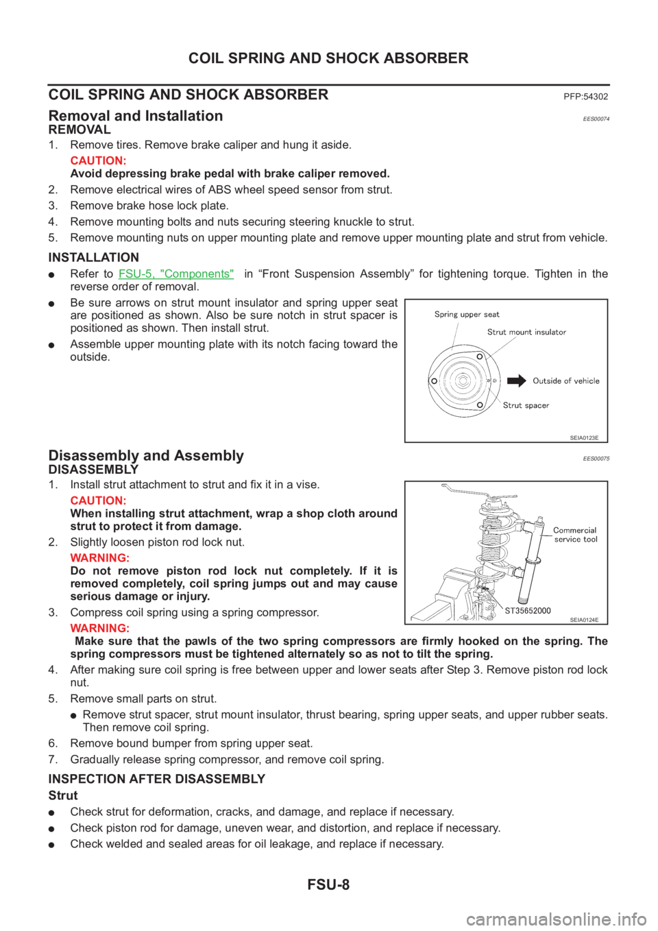
●Be sure arrows on strut mount insulator and spring upper seat
are positioned as shown. Also be sure notch in strut spacer is
positioned as shown. Then install strut.
●Assemble upper mounting plate with its notch facing toward the
outside.
Disassembly and AssemblyEES00075
DISASSEMBLY
1. Install strut attachment to strut and fix it in a vise.
CAUTION:
When installing strut attachment, wrap a shop cloth around
strut to protect it from damage.
2. Slightly loosen piston rod lock nut.
WARNING:
Do not remove piston rod lock nut completely. If it is
removed completely, coil spring jumps out and may cause
serious damage or injury.
3. Compress coil spring using a spring compressor.
WARNING:
Make sure that the pawls of the two spring compressors are firmly hooked on the spring. The
spring compressors must be tightened alternately so as not to tilt the spring.
4. After making sure coil spring is free between upper and lower seats after Step 3. Remove piston rod lock
nut.
5. Remove small parts on strut.
●Remove strut spacer, strut mount insulator, thrust bearing, spring upper seats, and upper rubber seats.
Then remove coil spring.
6. Remove bound bumper from spring upper seat.
7. Gradually release spring compressor, and remove coil spring.
INSPECTION AFTER DISASSEMBLY
Strut
●Check strut for deformation, cracks, and damage, and replace if necessary.
●Check piston rod for damage, uneven wear, and distortion, and replace if necessary.
●Check welded and sealed areas for oil leakage, and replace if necessary.
SEIA0123E
SEIA0124E
Page 2715 of 3833
COIL SPRING AND SHOCK ABSORBER
FSU-9
C
D
F
G
H
I
J
K
L
MA
B
FSU
Insulator and Rubber Parts
Check strut mount insulator for cracks and rubber parts for wear. Replace them if necessary.
Coil Spring
Check for cracks, wear, and damage, and replace if necessary.
ASSEMBLY
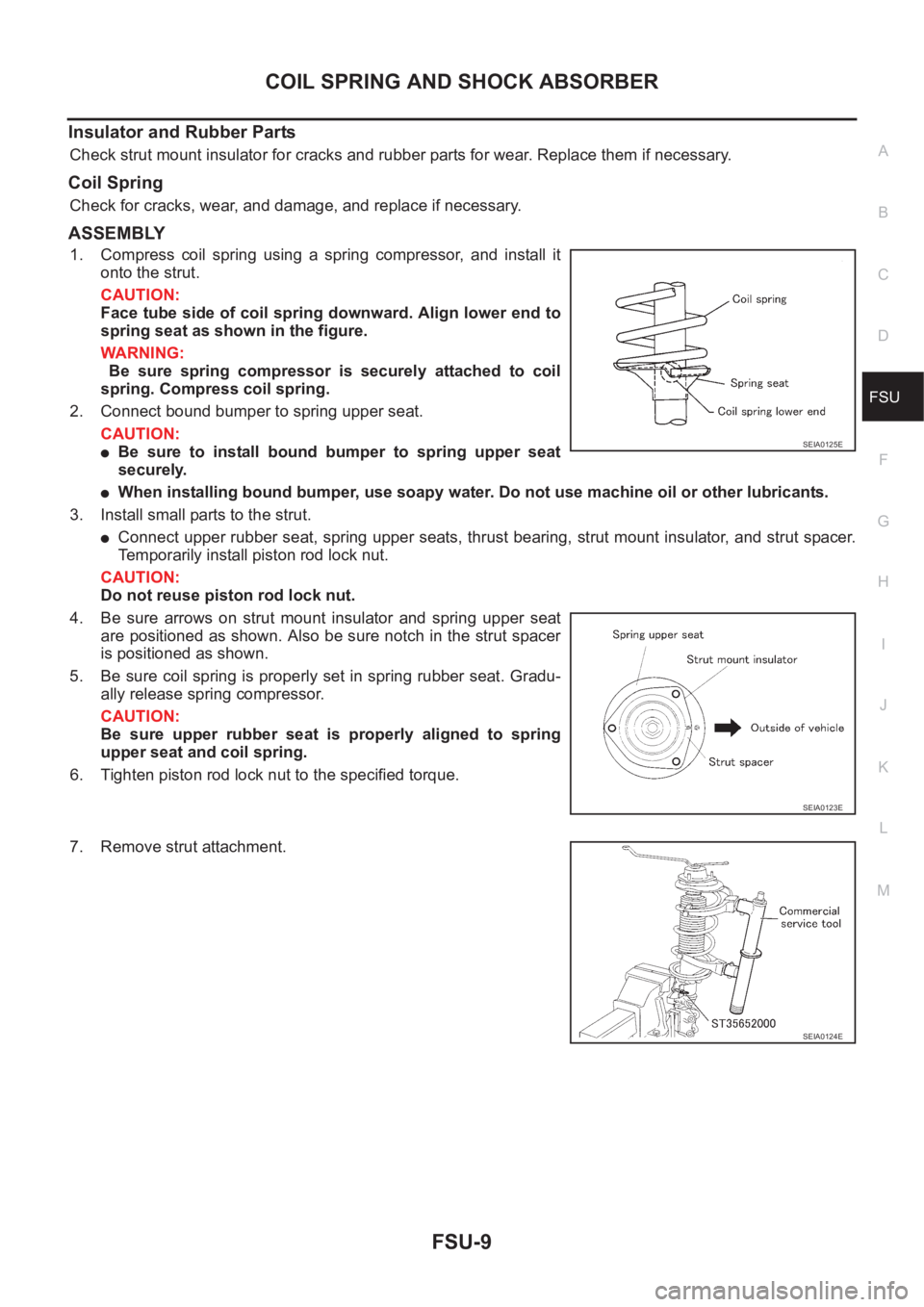
1. Compress coil spring using a spring compressor, and install it
onto the strut.
CAUTION:
Face tube side of coil spring downward. Align lower end to
spring seat as shown in the figure.
WARNING:
Be sure spring compressor is securely attached to coil
spring. Compress coil spring.
2. Connect bound bumper to spring upper seat.
CAUTION:
●Be sure to install bound bumper to spring upper seat
securely.
●When installing bound bumper, use soapy water. Do not use machine oil or other lubricants.
3. Install small parts to the strut.
●Connect upper rubber seat, spring upper seats, thrust bearing, strut mount insulator, and strut spacer.
Temporarily install piston rod lock nut.
CAUTION:
Do not reuse piston rod lock nut.
4. Be sure arrows on strut mount insulator and spring upper seat
are positioned as shown. Also be sure notch in the strut spacer
is positioned as shown.
5. Be sure coil spring is properly set in spring rubber seat. Gradu-
ally release spring compressor.
CAUTION:
Be sure upper rubber seat is properly aligned to spring
upper seat and coil spring.
6. Tighten piston rod lock nut to the specified torque.
7. Remove strut attachment.
SEIA0125E
SEIA0123E
SEIA0124E
Page 2728 of 3833
RSU-8
COIL SPRING AND STRUT
COIL SPRING AND STRUT
PFP:55302
Removal and InstallationEES0007H
REMOVAL
1. Remove tires.
2. Remove brake hose lock plate and remove brake hose from strut.
3. Remove mounting nuts and washers on upper portion of stabilizer connecting rod.
4. Remove strut-to-axle housing mounting bolts and nuts.
5. Remove luggage side lower finisher in luggage compartment. Remove mounting nuts on strut spacer.
Then remove strut from vehicle.
INSTALLATION
●Refer to RSU-5, "Components" for tightening torque. Install in the reverse order of removal.
Disassembly and AssemblyEES0007I
DISASSEMBLY
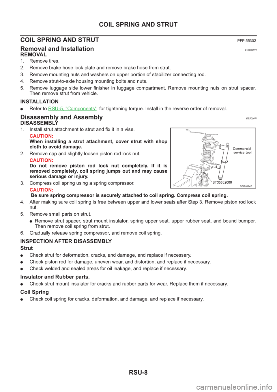
1. Install strut attachment to strut and fix it in a vise.
CAUTION:
When installing a strut attachment, cover strut with shop
cloth to avoid damage.
2. Remove cap and slightly loosen piston rod lock nut.
CAUTION:
Do not remove piston rod lock nut completely. If it is
removed completely, coil spring jumps out and may cause
serious damage or injury.
3. Compress coil spring using a spring compressor.
CAUTION:
Be sure spring compressor is securely attached to coil spring. Compress coil spring.
4. After making sure coil spring is free between upper and lower seats after Step 3. Remove piston rod lock
nut.
5. Remove small parts on strut.
●Remove strut spacer, strut mount insulator, spring upper seat, upper rubber seat, and bound bumper.
Then remove coil spring from strut.
6. Gradually release spring compressor, and remove coil spring.
INSPECTION AFTER DISASSEMBLY
Strut
●Check strut for deformation, cracks, and damage, and replace if necessary.
●Check piston rod for damage, uneven wear, and distortion, and replace if necessary.
●Check welded and sealed areas for oil leakage, and replace if necessary.
Insulator and Rubber parts.
●Check strut mount insulator for cracks and rubber parts for wear. Replace them if necessary.
Coil Spring
●Check coil spring for cracks, deformation, and damage, and replace if necessary.
SEIA0124E
Page 2729 of 3833
COIL SPRING AND STRUT
RSU-9
C
D
F
G
H
I
J
K
L
MA
B
RSU
ASSEMBLY
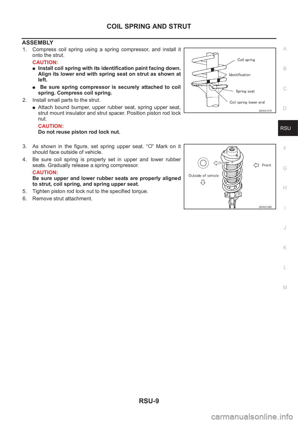
1. Compress coil spring using a spring compressor, and install it
onto the strut.
CAUTION:
●Install coil spring with its identification paint facing down.
Align its lower end with spring seat on strut as shown at
left.
● Be sure spring compressor is securely attached to coil
spring. Compress coil spring.
2. Install small parts to the strut.
●Attach bound bumper, upper rubber seat, spring upper seat,
strut mount insulator and strut spacer. Position piston rod lock
nut.
CAUTION:
Do not reuse piston rod lock nut.
3. As shown in the figure, set spring upper seat. “ ” Mark on it
should face outside of vehicle.
4. Be sure coil spring is properly set in upper and lower rubber
seats. Gradually release a spring compressor.
CAUTION:
Be sure upper and lower rubber seats are properly aligned
to strut, coil spring, and spring upper seat.
5. Tighten piston rod lock nut to the specified torque.
6. Remove strut attachment.SEIA0127E
SEIA0128E
Page 2763 of 3833
FRONT DISC BRAKE
BR-23
C
D
E
G
H
I
J
K
L
MA
B
BR
INSTALLATION
CAUTION:
●Refill with new brake fluid “DOT 3” or “DOT 4”.
●Never reuse drained brake fluid.
1. Install disc rotor.
2. Install caliper assembly. Tighten mounting bolts to the specified torque.
CAUTION:
Before installing caliper assembly, wipe oil and grease on steering knuckle washer seats and cali-
per assembly mounting surface.
3. Connect brake hose to caliper assembly and tighten union bolts to the specified torque.
CAUTION:
●Do not reuse the copper washer for union bolts.
●Securely assemble brake hose to protrusions on cylinder body.
4. Bleed air. Refer to BR-10, "
Bleeding Brake System" .
Caliper Disassembly and Assembly EFS000CK
DISASSEMBLY
WARNING:
Be careful not to pinch your fingers in the piston.
CAUTION:
Be careful not to damage the cylinder inner wall.
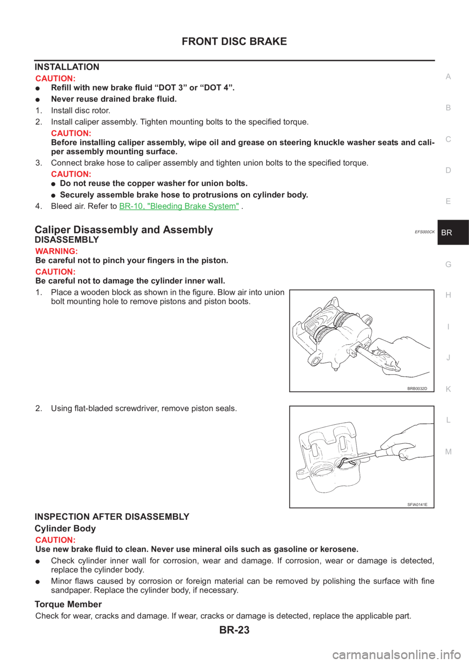
1. Place a wooden block as shown in the figure. Blow air into union
bolt mounting hole to remove pistons and piston boots.
2. Using flat-bladed screwdriver, remove piston seals.
INSPECTION AFTER DISASSEMBLY
Cylinder Body
CAUTION:
Use new brake fluid to clean. Never use mineral oils such as gasoline or kerosene.
●Check cylinder inner wall for corrosion, wear and damage. If corrosion, wear or damage is detected,
replace the cylinder body.
●Minor flaws caused by corrosion or foreign material can be removed by polishing the surface with fine
sandpaper. Replace the cylinder body, if necessary.
Torque Member
Check for wear, cracks and damage. If wear, cracks or damage is detected, replace the applicable part.
BRB0032D
SFIA0141E
Page 2768 of 3833
BR-28
REAR DISC BRAKE
Caliper Removal and Installation
EFS00180
REMOVAL
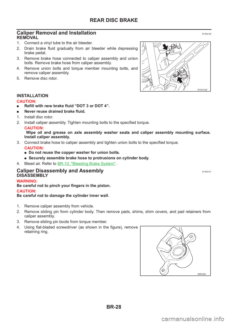
1. Connect a vinyl tube to the air bleeder.
2. Drain brake fluid gradually from air bleeder while depressing
brake pedal.
3. Remove brake hose connected to caliper assembly and union
bolts. Remove brake hose from caliper assembly.
4. Remove union bolts and torque member mounting bolts, and
remove caliper assembly.
5. Remove disc rotor.
INSTALLATION
CAUTION:
●Refill with new brake fluid “DOT 3 or DOT 4”.
●Never reuse drained brake fluid.
1. Install disc rotor.
2. Install caliper assembly. Tighten mounting bolts to the specified torque.
CAUTION:
Wipe oil and grease on axle assembly washer seats and caliper assembly mounting surface.
Install caliper assembly.
3. Connect brake hose to caliper assembly and tighten union bolts to the specified torque.
CAUTION:
●Do not reuse the copper washer for union bolts.
●Securely assemble brake hose to protrusions on cylinder body.
4. Bleed air. Refer to BR-10, "
Bleeding Brake System" .
Caliper Disassembly and AssemblyEFS00181
DISASSEMBLY
WARNING:
Be careful not to pinch your fingers in the piston.
CAUTION:
Be careful not to damage the cylinder inner wall.
1. Remove caliper assembly from vehicle.
2. Remove sliding pin from cylinder body. Then remove pads, shims, shim covers, and pad retainers from
caliper assembly.
3. Remove sliding pin boots from torque member.
4. Using flat-bladed screwdriver (as shown in the figure), remove
retaining ring.
SFIA0143E
SBR028A