Page 3109 of 3833
MULTI-REMOTE CONTROL SYSTEM
BL-57
C
D
E
F
G
H
J
K
L
MA
B
BL
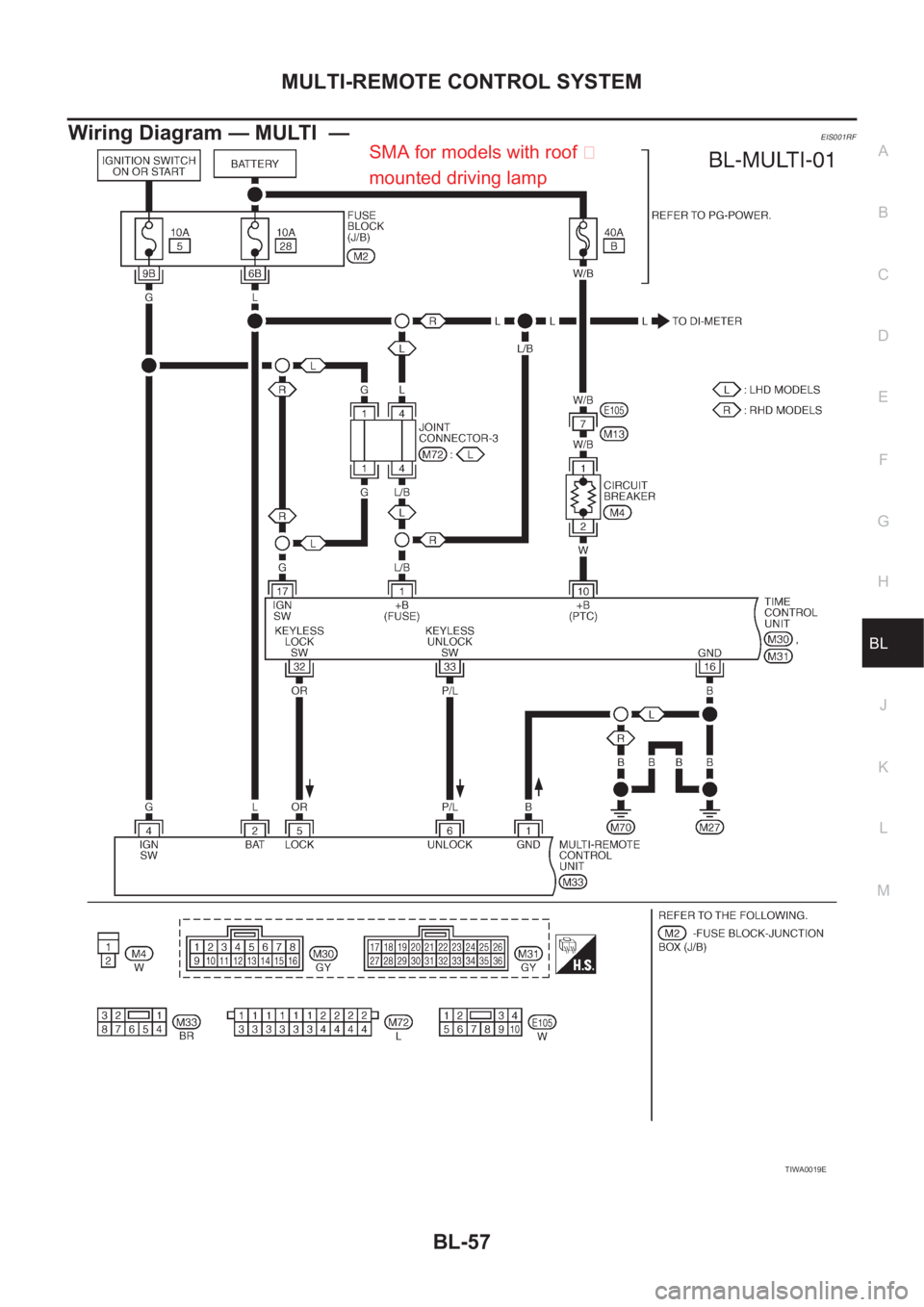
Wiring Diagram — MULTI —EIS001RF
TIWA0019E
SMA for models with roof �
mounted driving lamp
Page 3110 of 3833
BL-58
MULTI-REMOTE CONTROL SYSTEM
TIWA0020E
Page 3111 of 3833

MULTI-REMOTE CONTROL SYSTEM
BL-59
C
D
E
F
G
H
J
K
L
MA
B
BL
Terminal and Reference Value for Multi-remote Control UnitEIS001TQ
Symptom ChartEIS001RG
NOTE:
Always check remote controller battery before replacing remote controller.
Remote Controller Battery CheckEIS001T3
1.CHECK REMOTE CONTROLLER BATTERY
Remove battery and measure voltage across battery positive and
negative terminals, (+) and (−).
NOTE:
Remote controller does not function if battery is not set correctly.
OK or NG
OK >> Check remote controller battery terminals for corrosion
or damage.
NG >> Replace battery.
Te r m i -
nalWire
ColorItem ConditionVo l ta g e
(Approximate values)
1 B Ground — 0V
2 L BAT power supply — 12V
3 G/Y Hazard reminder (Flasher RH) Remote controller switch pressed0V → 12V
4 G IGN power supply — 12V
5 OR Key less lock sw Remote controller lock switch pressed 0V → 5V
6 P/L Key less unlock sw Remote controller unlock switch pressed 0V → 5V
7 Y/G Driver door lock switch signalUnlock (ON) 0V
Lock (OFF) 5V
8 G/B Hazard reminder (Flasher LH) Remote controller switch pressed0V → 12V
Symptom Diagnoses/service procedureReference
page
All function of multi-remote control system do
not operate.1.Remote controller battery checkBL-59
2.Power supply and ground circuit for control unit checkBL-60
3.Replace remote controller.BL-64
The new ID of remote controller cannot be
entered.1.Remote controller battery checkBL-592.Power supply and ground circuit for control unit checkBL-60
3.Replace remote controller.BL-64
Door lock and unlock does not function.
(If the power door lock system does not operate
manually, check power door lock system.)1.Remote controller battery check BL-59
2.Replace remote controller.
BL-64
Door lock function does not operate with
remote controller.Time control unit lock circuit checkBL-61
Door unlock function does not operate with
remote controller.Time control unit unlock circuit check BL-62
Hazard reminder does not activate properly
when pressing lock or unlock button of remote
controller.1.Remote controller battery check BL-59
2.Hazard reminder checkBL-62
3.Replace remote controller.BL-64
Voltage : 2.5V – 3.0V
SEL237W
Page 3112 of 3833

BL-60
MULTI-REMOTE CONTROL SYSTEM
Power Supply and Ground Circuit Check
EIS001T4
1. CHECK POWER SUPPLY CIRCUIT FOR TIME CONTROL UNIT
1. Disconnect time control unit harness connector.
2. Check voltage between time control unit harness connector ter-
minal 1 or 10 and ground.
OK or NG
OK >> GO TO 2
NG >> Check the following.
●40A fusible link (letter B , located in fuse and fusible
link box)
●10A fuse [No. 28, located in fuse block (J/B)]
●M4 circuit breaker
●Harness for open or short between time control unit and fuse
2. CHECK POWER SUPPLY CIRCUIT FOR MULTI-REMOTE CONTROL UNIT
1. Disconnect multi-remote control unit harness connector.
2. Check voltage between multi-remote control unit harness con-
nector terminal 2 (L) and ground.
OK or NG
OK >> GO TO 3
NG >> Check the following.
●10A fuse [No. 28, located in fuse block (J/B)]
●Harness for open or short between multi-remote con-
trol unit and fuse
3. CHECK IGNITION SWITCH “ON” CIRCUIT
1. Disconnect multi-remote control unit harness connector.
2. Check voltage between multi-remote control unit terminal 4 and
ground while ignition switch is “ON”.
OK or NG
OK >> GO TO 4
NG >> Check the following.
●10A fuse [No. 5, located in fuse block (J/B)]
●Harness for open or short between multi-remote con-
trol unit and fuse. Battery voltage should exist.
SIIA1204E
Battery voltage should exist.
SIIA1228E
Battery voltage should exist.
SIIA1229E
Page 3113 of 3833

MULTI-REMOTE CONTROL SYSTEM
BL-61
C
D
E
F
G
H
J
K
L
MA
B
BL
4.CHECK GROUND CIRCUIT FOR TIME CONTROL UNIT
Check continuity between time control unit harness connector termi-
nal 16 and ground.
OK or NG
OK >> GO TO 5
NG >> Check ground harness.
5.CHECK GROUND CIRCUIT FOR MULTI-REMOTE CONTROL UNIT
Check continuity between multi-remote control unit terminal 1 and
ground.
OK or NG
OK >> Power supply and ground circuits are OK.
NG >> Check ground harness.
Time Control Unit Lock Signal Circuit CheckEIS004G8
1.CHECK TIME CONTROL UNIT OUTPUT SIGNAL
Check voltage between time control unit and ground.
OK or NG
OK >> Replace time control unit.
NG >> GO TO 2.
2.CHECK TIME CONTROL UNIT CIRCUIT
1. Turn ignition switch OFF.
2. Disconnect time control unit connector and multi-remote control
unit connector.
3. Check continuity between time control unit harness connector
M31 terminal 32 (OR) and multi-remote control unit harness
connector M33 terminal 5 (OR)
OK or NG
OK >> Replace multi-remote control unit.
NG >> Repair harness or connector.Continuity should exist.
PIIA3646E
Continuity should exist.
SIIA1230E
Terminals
Condition of
remote con-
trollerVoltage [V]
(Approximate
values) (+)
(-)
ConnectorTerminal
(Wire color)
M31 32 (OR) GroundLock switch
pressed5V → 0V
Unlock switch
pressed5V
SIIA2240E
Continuity should exist.
SIIA2241E
Page 3114 of 3833

BL-62
MULTI-REMOTE CONTROL SYSTEM
Time Control Unit Unlock Signal Circuit Check
EIS004G9
1. CHECK TIME CONTROL UNIT OUTPUT SIGNAL
Check voltage between time control unit and ground.
OK or NG
OK >> Replace time control unit.
NG >> GO TO 2.
2. CHECK TIME CONTROL UNIT CIRCUIT
1. Turn ignition switch OFF.
2. Disconnect time control unit connector and multi-remote control
unit connector.
3. Check continuity between time control unit harness connector
M31 terminal 33 (P/L) and multi-remote control unit harness
connector M33 terminal 6 (P/L)
OK or NG
OK >> Replace multi-remote control unit.
NG >> Repair harness or connector.
Hazard Reminder CheckEIS001T5
1. CHECK HAZARD WARNING LAMP
Check if hazard warning lamp flashes with hazard switch.
Does hazard warning lamp operate?
Yes >> GO TO 2
No >> Check hazard warning lamp circuit.
2. CHECK HAZARD REMINDER OPERATION
Check the following at when push the multi-remote control switch.
Check voltage between multi-remote control unit terminal 3 (G/Y), 8
(G/B) and ground.
OK or NG
OK >> Check harness for open or short between multi remote
control unit and hazard switch.
NG >> Replace multi-remote control unit.
Terminals
Condition of
remote con-
trollerVoltage [V]
(Approximate
values) (+)
(-)
ConnectorTerminal
(Wire color)
M31 33 (P/L) GroundLock switch
pressed5V
Unlock switch
pressed5V → 0V
SIIA2242E
Continuity should exist.
SIIA2243E
Battery voltage should exist.
SIIA1231E
Page 3115 of 3833
MULTI-REMOTE CONTROL SYSTEM
BL-63
C
D
E
F
G
H
J
K
L
MA
B
BL
ID Code Entry ProcedureEIS001RH
SEL497X
Page 3116 of 3833
BL-64
MULTI-REMOTE CONTROL SYSTEM
Remote Controller Battery Replacement
EIS001RI
SEL241X