2001 NISSAN X-TRAIL open hood
[x] Cancel search: open hoodPage 1502 of 3833
![NISSAN X-TRAIL 2001 Service Repair Manual EC-1152
[QR20(WITHOUT EURO-OBD)]
TROUBLE DIAGNOSIS
Basic Inspection
EBS00N3Z
1. INSPECTION START
1. Check service records for any recent repairs that may indicate a related incident, or NISSAN X-TRAIL 2001 Service Repair Manual EC-1152
[QR20(WITHOUT EURO-OBD)]
TROUBLE DIAGNOSIS
Basic Inspection
EBS00N3Z
1. INSPECTION START
1. Check service records for any recent repairs that may indicate a related incident, or](/manual-img/5/57405/w960_57405-1501.png)
EC-1152
[QR20(WITHOUT EURO-OBD)]
TROUBLE DIAGNOSIS
Basic Inspection
EBS00N3Z
1. INSPECTION START
1. Check service records for any recent repairs that may indicate a related incident, or a current need for
scheduled maintenance.
2. Open engine hood and check the following:
–Harness connectors for improper connections
–Wiring harness for improper connections, pinches and cut
–Vacuum hoses for splits, kinks and improper connections
–Hoses and ducts for leaks
–Air cleaner clogging
–Gasket
3. Confirm that electrical or mechanical loads are not applied.
–Headlamp switch is OFF.
–Air conditioner switch is OFF.
–Rear window defogger switch is OFF.
–Steering wheel is in the straight-ahead position, etc.
4. Start engine and warm it up until engine coolant temperature
indicator points the middle of gauge.
Ensure engine stays below 1,000 rpm.
5. Run engine at about 2,000 rpm for about 2 minutes under no-
load.
6. Make sure that no DTC is displayed with CONSULT-II or GST.
OK or NG
OK >> GO TO 3.
NG >> GO TO 2.
2. REPAIR OR REPLACE
Repair or replace components as necessary according to corresponding “Diagnostic Procedure”.
>> GO TO 3.
SEF983U
SEF976U
SEF977U
Page 1763 of 3833
![NISSAN X-TRAIL 2001 Service Repair Manual TROUBLE DIAGNOSIS
EC-1413
[YD]
C
D
E
F
G
H
I
J
K
L
MA
EC
1.INSPECTION START
1. Check service records for any recent repairs that may indicate a related incident.
2. Check the current need for schedule NISSAN X-TRAIL 2001 Service Repair Manual TROUBLE DIAGNOSIS
EC-1413
[YD]
C
D
E
F
G
H
I
J
K
L
MA
EC
1.INSPECTION START
1. Check service records for any recent repairs that may indicate a related incident.
2. Check the current need for schedule](/manual-img/5/57405/w960_57405-1762.png)
TROUBLE DIAGNOSIS
EC-1413
[YD]
C
D
E
F
G
H
I
J
K
L
MA
EC
1.INSPECTION START
1. Check service records for any recent repairs that may indicate a related incident.
2. Check the current need for scheduled maintenance, especially for fuel filter and air cleaner filter. Refer to
MA-7, "
PERIODIC MAINTENANCE" .
3. Open engine hood and check the following:
–Harness connectors for improper connections
–Vacuum hoses for splits, kinks, or improper connections
–Wiring for improper connections, pinches, or cuts
4. Start engine and warm it up to the normal operating tempera-
ture.
>> GO TO 2.
2.PREPARATION FOR CHECKING IDLE SPEED
With CONSULT-II
Connect CONSULT-II to the data link connector.
>> GO TO 3.
3.CHECK IDLE SPEED
With CONSULT-II
1. Select “CKPS·RPM (TDC)” in “DATA MONITOR” mode with CONSULT-II.
2. Read idle speed.
OK or NG
OK >>INSPECTION END
NG >> GO TO 4.
4.CHECK FOR INTAKE AIR LEAK
Listen for an intake air leak after the mass air flow sensor.
OK or NG
OK >> GO TO 5.
NG >> Repair or replace.
SEF142I
725±25 rpm
SEF817Y
Page 2827 of 3833
![NISSAN X-TRAIL 2001 Service Repair Manual TROUBLE DIAGNOSIS
BRC-43
[4WD/ABS]
C
D
E
G
H
I
J
K
L
MA
B
BRC
3.CHECK CONTINUITY BETWEEN IGNITION SWITCH AND ABS WARNING LAMP
●Disconnect 4WD/ABS control unit connector.
●Check continuity between NISSAN X-TRAIL 2001 Service Repair Manual TROUBLE DIAGNOSIS
BRC-43
[4WD/ABS]
C
D
E
G
H
I
J
K
L
MA
B
BRC
3.CHECK CONTINUITY BETWEEN IGNITION SWITCH AND ABS WARNING LAMP
●Disconnect 4WD/ABS control unit connector.
●Check continuity between](/manual-img/5/57405/w960_57405-2826.png)
TROUBLE DIAGNOSIS
BRC-43
[4WD/ABS]
C
D
E
G
H
I
J
K
L
MA
B
BRC
3.CHECK CONTINUITY BETWEEN IGNITION SWITCH AND ABS WARNING LAMP
●Disconnect 4WD/ABS control unit connector.
●Check continuity between ignition switch and 4WD/ABS control module terminal No. 4. (Open circuit
check)
Is inspection result OK?
YES >> Continuity exists. Connect 4WD/ABS control module connector, check again.
NO >> Continuity does not exist. Check ABS warning lamp path.
4.CHECK FUSE
●Check if Fuse No.8 is working normally.
Is the check result OK?
YES >> Repair or replace the harness in between 4WD/ABS control unit and IGN.
NO >> Replace the fuse and replace again.
●If the figure of the monitor is with in ± 10% of the set value of E-TS solenoid electric current, 4WD/ABS C/
U is operating normally. Check for electric control coupling ASSY is required.
4WD Warning Lamp Does Not Illuminate With Ignition ON.EFS001BR
1.INSPECTION OF BLOWN 4WD WARNING LAMP BULB
●Remove glove box on the passenger side and disconnect the 4WD/ABS control unit connector.
●Confirm continuity between 4WD/ABS control unit connector terminals No. 3 (IGN) and No. 4 (ABS warn-
ing lamp).
Is inspection result OK?
YES >> GO TO 3. (Continuity exists.)
NO >>
●Check 4WD warning lamp harness.
●Remove meter control module assembly and check for blown 4WD warning lamp bulb.
2.4WD ACTUATOR RELAY HARNESS INSPECTION
●Open the hood and check that the 4WD relay is properly installed in the relay box.
●Confirm continuity between 4WD/ABS control unit connector terminals No. 7 (4WD warning lamp) and No.
104 (ground).
●Confirm continuity between 4WD/ABS control unit connector terminals No. 3 (IGN) and No. 18 (4WD
actuator relay).
Is inspection result OK?
YES >> Continuity exists. Connect 4WD/ABS control unit connector, check again.
NO >> Check ABS warning lamp harness.
4WD Warning Lamp Does Not Go Out Several Seconds After Engine Is Started.
(Drive Mode Indicator Lamp Goes Out.)
EFS001BS
1.USING CONSULT, PERFORM SELF-DIAGNOSIS
4WD warning lamp does not go out several seconds after the engine is started. (Drive mode indicator lamp
goes out.)
Is inspection result OK?
YES >> No malfunction detected. Perform inspection again.
NO >>
●Determine the location of the malfunction according to the result of self-diagnosis using CON-
SULT. (Malfunction is present in the 4WD system.)
●CONSULT-II does not display ABS -related trouble codes. Proceed to 2.
Page 3058 of 3833

BL-6
HOOD
Install in the reverse order of removal.
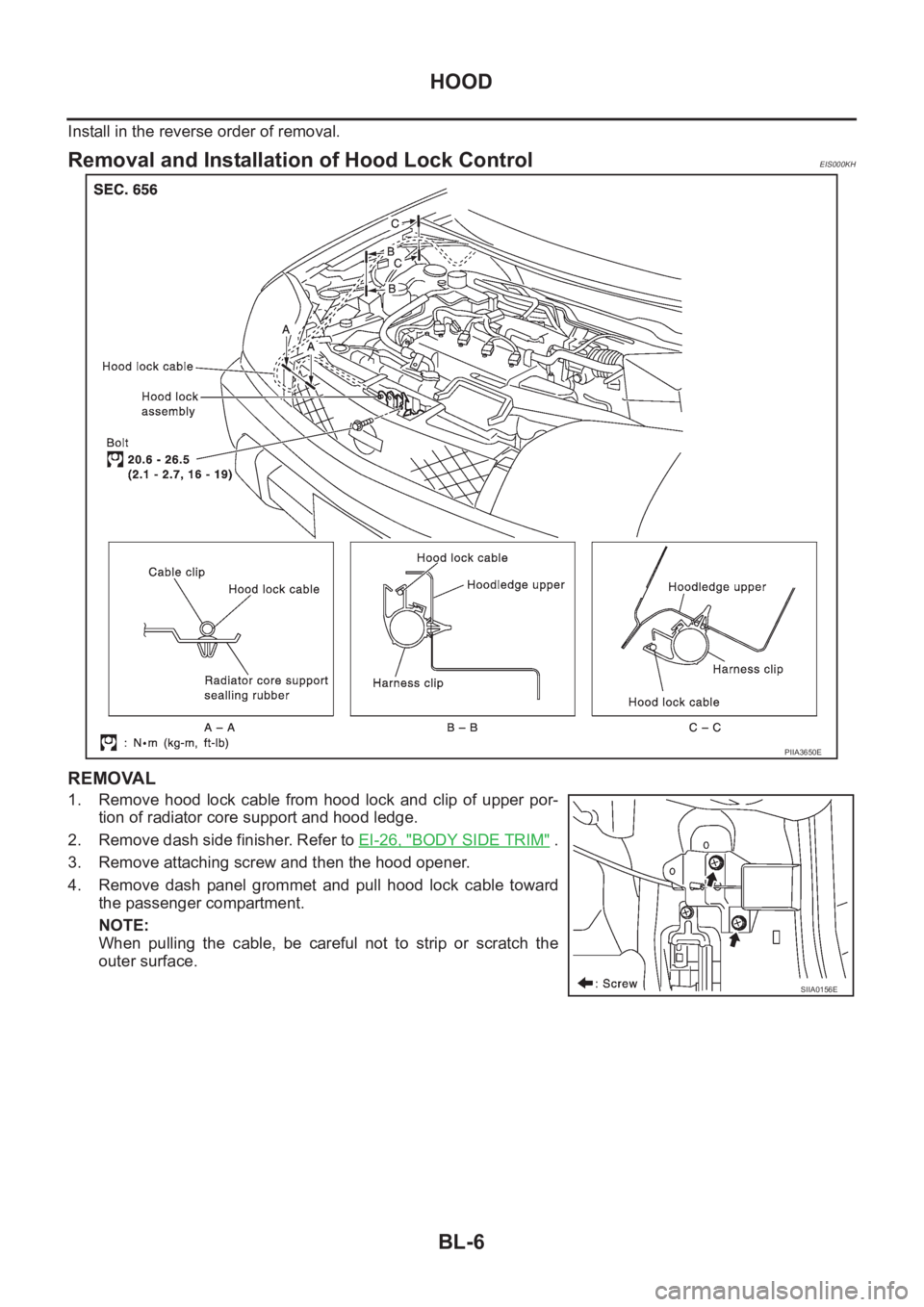
Removal and Installation of Hood Lock ControlEIS000KH
REMOVAL
1. Remove hood lock cable from hood lock and clip of upper por-
tion of radiator core support and hood ledge.
2. Remove dash side finisher. Refer to EI-26, "
BODY SIDE TRIM" .
3. Remove attaching screw and then the hood opener.
4. Remove dash panel grommet and pull hood lock cable toward
the passenger compartment.
NOTE:
When pulling the cable, be careful not to strip or scratch the
outer surface.
PIIA3650E
SIIA0156E
Page 3059 of 3833

HOOD
BL-7
C
D
E
F
G
H
J
K
L
MA
B
BL
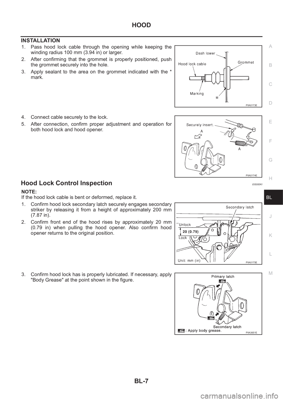
INSTALLATION
1. Pass hood lock cable through the opening while keeping the
winding radius 100 mm (3.94 in) or larger.
2. After confirming that the grommet is properly positioned, push
the grommet securely into the hole.
3. Apply sealant to the area on the grommet indicated with the *
mark.
4. Connect cable securely to the lock.
5. After connection, confirm proper adjustment and operation for
both hood lock and hood opener.
Hood Lock Control InspectionEIS000KI
NOTE:
If the hood lock cable is bent or deformed, replace it.
1. Confirm hood lock secondary latch securely engages secondary
striker by releasing it from a height of approximately 200 mm
(7.87 in).
2. Confirm front end of the hood rises by approximately 20 mm
(0.79 in) when pulling the hood opener. Also confirm hood
opener returns to the original position.
3. Confirm hood lock has is properly lubricated. If necessary, apply
"Body Grease" at the point shown in the figure.
PIIA0173E
PIIA0174E
PIIA0175E
PIIA3651E
Page 3366 of 3833

ATC-90
TROUBLE DIAGNOSIS
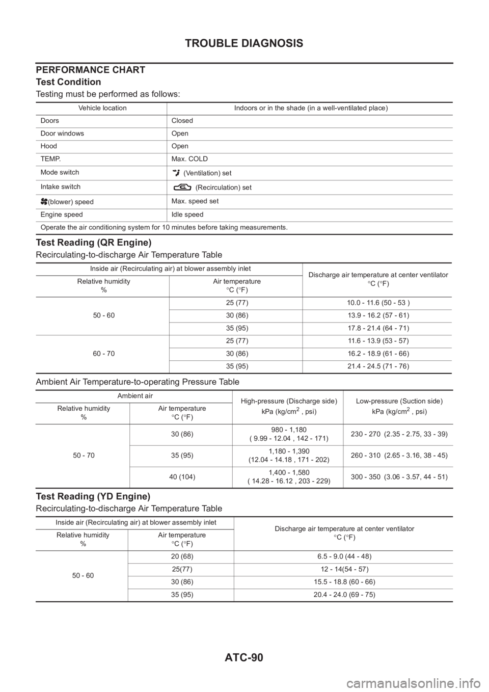
PERFORMANCE CHART
Test Condition
Testing must be performed as follows:
Test Reading (QR Engine)
Recirculating-to-discharge Air Temperature Table
Ambient Air Temperature-to-operating Pressure Table
Test Reading (YD Engine)
Recirculating-to-discharge Air Temperature Table
Vehicle location Indoors or in the shade (in a well-ventilated place)
Doors Closed
Door windows Open
Hood Open
TEMP. Max. COLD
Mode switch
(Ventilation) set
Intake switch
(Recirculation) set
(blower) speedMax. speed set
Engine speed Idle speed
Operate the air conditioning system for 10 minutes before taking measurements.
Inside air (Recirculating air) at blower assembly inlet
Discharge air temperature at center ventilator
°C (°F) Relative humidity
%Air temperature
°C (°F)
50 - 6025 (77) 10.0 - 11.6 (50 - 53 )
30 (86) 13.9 - 16.2 (57 - 61)
35 (95) 17.8 - 21.4 (64 - 71)
60 - 7025 (77) 11.6 - 13.9 (53 - 57)
30 (86) 16.2 - 18.9 (61 - 66)
35 (95) 21.4 - 24.5 (71 - 76)
Ambient air
High-pressure (Discharge side)
kPa (kg/cm
2 , psi)Low-pressure (Suction side)
kPa (kg/cm2 , psi) Relative humidity
%Air temperature
°C (°F)
50 - 7030 (86)980 - 1,180
( 9.99 - 12.04 , 142 - 171)230 - 270 (2.35 - 2.75, 33 - 39)
35 (95)1,180 - 1,390
(12.04 - 14.18 , 171 - 202)260 - 310 (2.65 - 3.16, 38 - 45)
40 (104)1,400 - 1,580
( 14.28 - 16.12 , 203 - 229)300 - 350 (3.06 - 3.57, 44 - 51)
Inside air (Recirculating air) at blower assembly inlet
Discharge air temperature at center ventilator
°C (°F) Relative humidity
%Air temperature
°C (°F)
50 - 6020 (68) 6.5 - 9.0 (44 - 48)
25(77) 12 - 14(54 - 57)
30 (86) 15.5 - 18.8 (60 - 66)
35 (95) 20.4 - 24.0 (69 - 75)
Page 3376 of 3833

ATC-100
TROUBLE DIAGNOSIS
Ambient Sensor Circuit
EJS001HB
COMPONENT DESCRIPTION
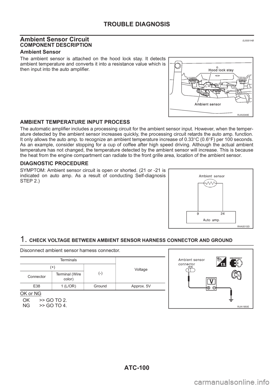
Ambient Sensor
The ambient sensor is attached on the hood lock stay. It detects
ambient temperature and converts it into a resistance value which is
then input into the auto amplifier.
AMBIENT TEMPERATURE INPUT PROCESS
The automatic amplifier includes a processing circuit for the ambient sensor input. However, when the temper-
ature detected by the ambient sensor increases quickly, the processing circuit retards the auto amp. function.
It only allows the auto amp. to recognize an ambient temperature increase of 0.33°C (0.6°F) per 100 seconds.
As an example, consider stopping for a cup of coffee after high speed driving. Although the actual ambient
temperature has not changed, the temperature detected by the ambient sensor will increase. This is because
the heat from the engine compartment can radiate to the front grille area, location of the ambient sensor.
DIAGNOSTIC PROCEDURE
SYMPTOM: Ambient sensor circuit is open or shorted. (21 or -21 is
indicated on auto amp. As a result of conducting Self-diagnosis
STEP 2.)
1. CHECK VOLTAGE BETWEEN AMBIENT SENSOR HARNESS CONNECTOR AND GROUND
Disconnect ambient sensor harness connector.
OK or NG
OK >> GO TO 2.
NG >> GO TO 4.
RJIA0048E
RHA051GD
Terminals
Voltage (+)
(-)
ConnectorTerminal (Wire
color)
E38 1 (L/OR) Ground Approx. 5V
RJIA1950E
Page 3786 of 3833

MA-6
GENERAL MAINTENANCE
GENERAL MAINTENANCE
PFP:00000
General MaintenanceELS000AL
General maintenance includes those items which should be checked during the normal day-to-day operation
of the vehicle. They are essential if the vehicle is to continue operating properly. The owners can perform the
checks and inspections themselves or they can have their NISSAN dealers do them for a nominal charge.
OUTSIDE THE VEHICLE
The maintenance items listed here should be performed from time to time, unless otherwise specified.
INSIDE THE VEHICLE
The maintenance items listed here should be checked on a regular basis, such as when performing periodic maintenance, cleaning the
vehicle, etc.
UNDER THE HOOD AND VEHICLE
The maintenance items listed here should be checked periodically e.g. each time you check the engine oil or refuel. Item Reference page
TiresCheck the pressure with a gauge periodically when at a service station, includ-
ing the spare, and adjust to the specified pressure if necessary. Check carefully
for damage, cuts or excessive wear.—
Windshield wiper
bladesCheck for cracks or wear if not functioning correctly. —
Doors and engine
hoodCheck that all doors, the engine hood, the trunk lid and back door operate prop-
erly. Also ensure that all latches lock securely. Lubricate if necessary. Make sure
that the secondary latch keeps the hood from opening when the primary latch is
released.
When driving in areas using road salt or other corrosive materials, check for
lubrication frequently.BL-4
,BL-8
Tire rotationTires should be rotated every 5,000 km (3,000 miles).MA-38
Item Reference page
LampsMake sure that the headlamps, stop lamps, tail lamps, turn signal lamps, and
other lamps are all operating properly and installed securely. Also check head-
lamp aim.—
Warning lamps and
chimesMake sure that all warning lamps and buzzers/chimes are operating properly. —
Steering wheelCheck that it has the specified play.
Check for changes in the steering conditions, such as excessive free play, hard
steering or strange noises.
Free play: Less than 35 mm (1.38 in)—
Seat beltsCheck that all parts of the seat belt system (e.g. buckles, anchors, a dju sters and
retractors) operate properly and smoothly, and are installed securely. Check the
belt webbing for cuts, fraying, wear or damage.SB-3
Item Reference page
Windshield washer
fluidCheck that there is adequate fluid in the tank. —
Engine coolant levelCheck the coolant level when the engine is cold.CO-29
(QR20DE,
QR25DE)
CO-29
(YD22DDTi)
Engine oil levelCheck the level after parking the vehicle (on level ground) and turning off the
engine.LU-18
(QR20DE,
QR25DE)
LU-18
(YD22DDTi)
Brake and clutch fluid
levelsMake sure that the brake and clutch fluid levels are between the “MAX” and
“MIN” lines on the reservoir.MA-35
,MA-39
BatteryCheck the fluid level in each cell. It should be between the “MAX” and “MIN”
lines.—