2001 NISSAN X-TRAIL transmission
[x] Cancel search: transmissionPage 3277 of 3833
ATC-1
AUTOMATIC AIR CONDITIONER
J AIR CONDITIONER
CONTENTS
C
D
E
F
G
H
I
K
L
M
SECTION
A
B
AT C
AUTOMATIC AIR CONDITIONER
PRECAUTIONS .......................................................... 4
Precautions for Supplemental Restraint System
(SRS) “AIR BAG” and “SEAT BELT PRE-TEN-
SIONER” .................................................................. 4
Precautions for Working with HFC-134a (R-134a) ..... 4
General Refrigerant Precautions .............................. 5
Lubricant Precautions .............................................. 5
Precautions for Refrigerant Connection ................... 5
FEATURES OF NEW TYPE REFRIGERANT
CONNECTION ...................................................... 6
O-RING AND REFRIGERANT CONNECTION ..... 7
Precautions for Servicing Compressor ..................... 9
Precautions for Service Equipment ........................ 10
RECOVERY/RECYCLING EQUIPMENT ............ 10
ELECTRONIC LEAK DETECTOR ...................... 10
VACUUM PUMP ................................................. 10
MANIFOLD GAUGE SET .................................... 10
SERVICE HOSES ................................................ 11
SERVICE COUPLERS ......................................... 11
REFRIGERANT WEIGHT SCALE ....................... 11
CALIBRATING ACR4 WEIGHT SCALE ............... 11
CHARGING CYLINDER ...................................... 12
Precautions for Leak Detection Dye ....................... 12
IDENTIFICATION ................................................ 12
IDENTIFICATION LABEL FOR VEHICLE ........... 13
Wiring Diagrams and Trouble Diagnosis ................ 13
PREPARATION ......................................................... 14
Special Service Tools ............................................. 14
WITH GASOLINE ENGINE (CWV-615M COM-
PRESSOR) ......................................................... 14
WITH DIESEL ENGINE (DKV-11G COMPRES-
SOR) ................................................................... 14
HFC-134a (R-134a) Service Tools and Equipment ... 15
REFRIGERATION SYSTEM ..................................... 18
Refrigerant Cycle ................................................... 18
REFRIGERANT FLOW ....................................... 18
FREEZE PROTECTION (WITH GASOLINE
ENGINE: CWV-615M COMPRESSOR) .............. 18
Refrigerant System Protection ............................... 18
REFRIGERANT PRESSURE SENSOR (WITH GASOLINE ENGINE: CWV-615M COMPRES-
SOR) ................................................................... 18
DUAL-PRESSURE SWITCH (WITH DIESEL
ENGINE: DKV-11G COMPRESSOR) .................. 18
PRESSURE RELIEF VALVE (WITH GASOLINE
ENGINE: CWV-615M COMPRESSOR) .............. 18
V-6 Variable Displacement Compressor (With Gas-
oline Engine: CWV-615M Compressor) .................. 19
GENERAL INFORMATION ................................. 19
DESCRIPTION .................................................... 20
Component Layout ................................................. 23
LUBRICANT .............................................................. 24
Maintenance of Lubricant Quantity in Compressor ... 24
LUBRICANT ........................................................ 24
LUBRICANT RETURN OPERATION .................. 24
LUBRICANT ADJUSTING PROCEDURE FOR
COMPONENTS REPLACEMENT EXCEPT
COMPRESSOR .................................................. 25
LUBRICANT ADJUSTING PROCEDURE FOR
COMPRESSOR REPLACEMENT ....................... 25
AIR CONDITIONER CONTROL ............................... 27
Overview Air Conditioner LAN Control System ...... 27
System Construction .............................................. 27
OPERATION ........................................................ 27
TRANSMISSION DATA AND TRANSMISSION
ORDER ............................................................... 28
AIR MIX DOOR CONTROL (AUTOMATIC TEM-
PERATURE CONTROL) ..................................... 28
FAN SPEED CONTROL ...................................... 29
INTAKE DOOR CONTROL ................................. 29
OUTLET DOOR CONTROL ................................ 29
MAGNET CLUTCH CONTROL ........................... 29
SELF-DIAGNOSTIC SYSTEM ............................ 29
Overview of Control system .................................... 29
Control Operation ................................................... 30
DISPLAY SCREEN .............................................. 30
AUTO SWITCH ................................................... 30
TEMPERATURE DIAL (POTENTIO TEMPERA-
TURE CONTROL) ............................................... 30
A/C SWITCH ....................................................... 30
Page 3303 of 3833
AIR CONDITIONER CONTROL
ATC-27
C
D
E
F
G
H
I
K
L
MA
B
AT C
AIR CONDITIONER CONTROLPFP:27500
Overview Air Conditioner LAN Control SystemEJS000TI
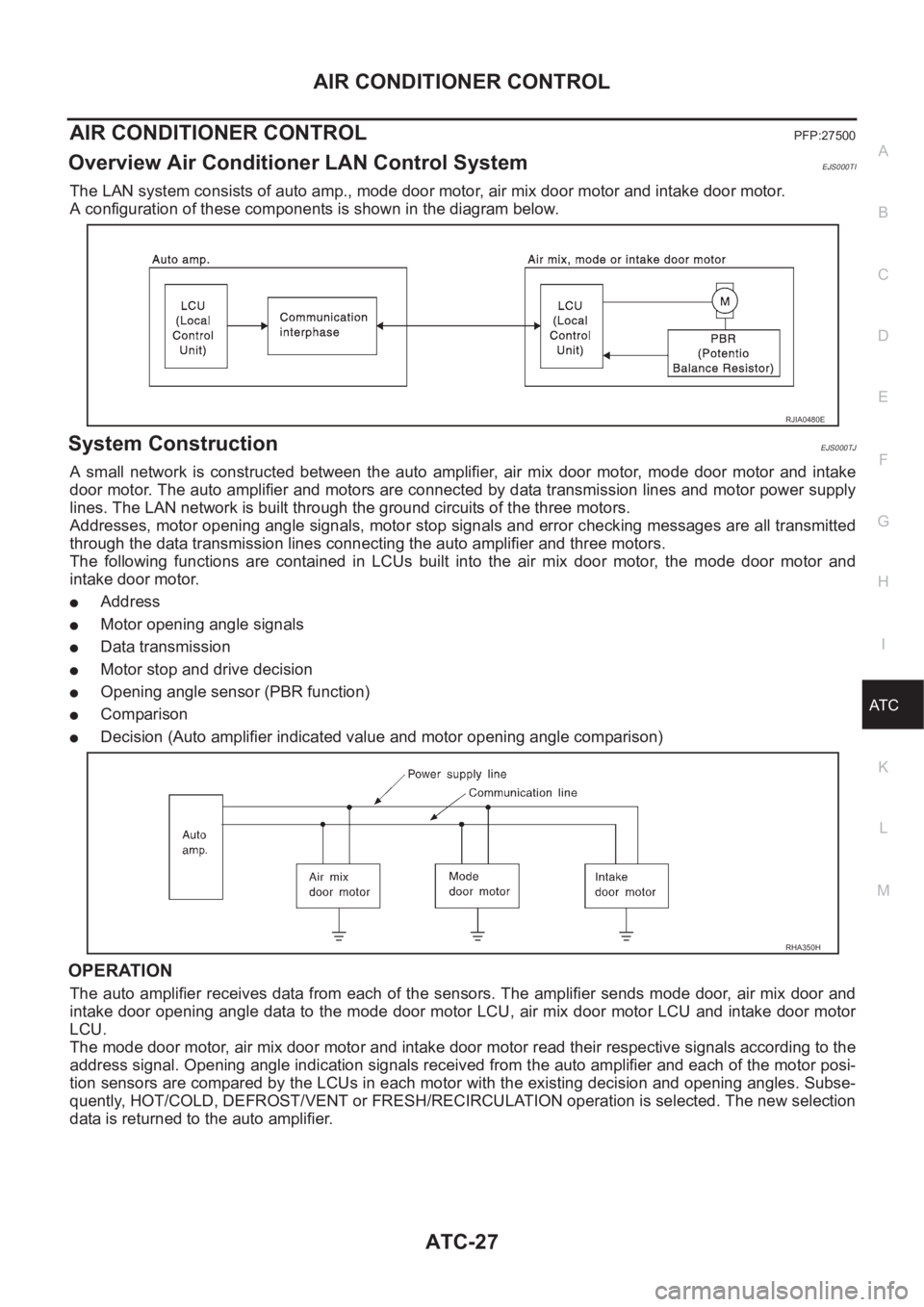
The LAN system consists of auto amp., mode door motor, air mix door motor and intake door motor.
A configuration of these components is shown in the diagram below.
System ConstructionEJS000TJ
A small network is constructed between the auto amplifier, air mix door motor, mode door motor and intake
door motor. The auto amplifier and motors are connected by data transmission lines and motor power supply
lines. The LAN network is built through the ground circuits of the three motors.
Addresses, motor opening angle signals, motor stop signals and error checking messages are all transmitted
through the data transmission lines connecting the auto amplifier and three motors.
The following functions are contained in LCUs built into the air mix door motor, the mode door motor and
intake door motor.
●Address
●Motor opening angle signals
●Data transmission
●Motor stop and drive decision
●Opening angle sensor (PBR function)
●Comparison
●Decision (Auto amplifier indicated value and motor opening angle comparison)
OPERATION
The auto amplifier receives data from each of the sensors. The amplifier sends mode door, air mix door and
intake door opening angle data to the mode door motor LCU, air mix door motor LCU and intake door motor
LCU.
The mode door motor, air mix door motor and intake door motor read their respective signals according to the
address signal. Opening angle indication signals received from the auto amplifier and each of the motor posi-
tion sensors are compared by the LCUs in each motor with the existing decision and opening angles. Subse-
quently, HOT/COLD, DEFROST/VENT or FRESH/RECIRCULATION operation is selected. The new selection
data is returned to the auto amplifier.
RJIA0480E
RHA350H
Page 3304 of 3833
ATC-28
AIR CONDITIONER CONTROL
TRANSMISSION DATA AND TRANSMISSION ORDER
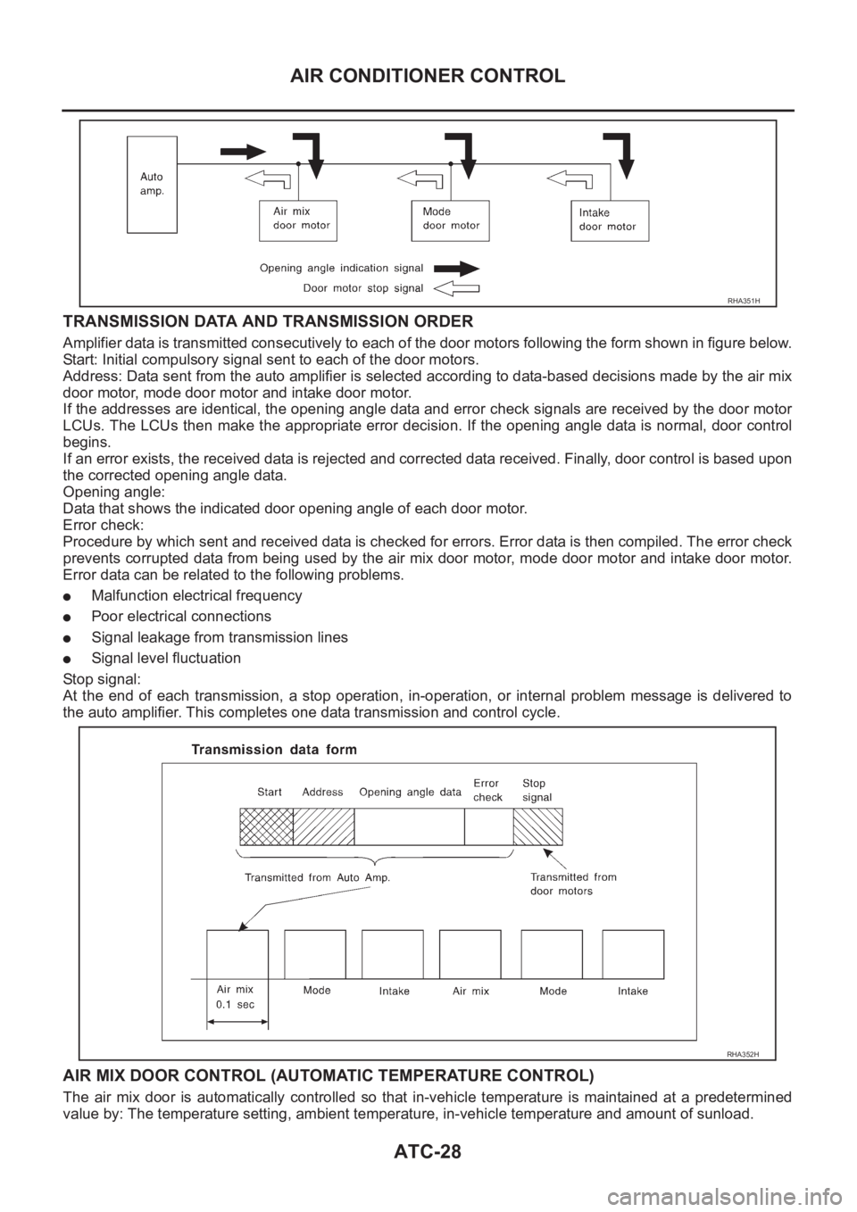
Amplifier data is transmitted consecutively to each of the door motors following the form shown in figure below.
Start: Initial compulsory signal sent to each of the door motors.
Address: Data sent from the auto amplifier is selected according to data-based decisions made by the air mix
door motor, mode door motor and intake door motor.
If the addresses are identical, the opening angle data and error check signals are received by the door motor
LCUs. The LCUs then make the appropriate error decision. If the opening angle data is normal, door control
begins.
If an error exists, the received data is rejected and corrected data received. Finally, door control is based upon
the corrected opening angle data.
Opening angle:
Data that shows the indicated door opening angle of each door motor.
Error check:
Procedure by which sent and received data is checked for errors. Error data is then compiled. The error check
prevents corrupted data from being used by the air mix door motor, mode door motor and intake door motor.
Error data can be related to the following problems.
●Malfunction electrical frequency
●Poor electrical connections
●Signal leakage from transmission lines
●Signal level fluctuation
St op s ign al :
At the end of each transmission, a stop operation, in-operation, or internal problem message is delivered to
the auto amplifier. This completes one data transmission and control cycle.
AIR MIX DOOR CONTROL (AUTOMATIC TEMPERATURE CONTROL)
The air mix door is automatically controlled so that in-vehicle temperature is maintained at a predetermined
value by: The temperature setting, ambient temperature, in-vehicle temperature and amount of sunload.
RHA351H
RHA352H
Page 3665 of 3833
![NISSAN X-TRAIL 2001 Service Repair Manual CAN COMMUNICATION
LAN-3
[CAN]
C
D
E
F
G
H
I
J
L
MA
B
LAN
CAN COMMUNICATIONPFP:23710
System DescriptionEKS001U3
CAN (Controller Area Network) is a serial communication line for real time application. I](/manual-img/5/57405/w960_57405-3664.png "NISSAN X-TRAIL 2001 Service Repair Manual CAN COMMUNICATION
LAN-3
[CAN]
C
D
E
F
G
H
I
J
L
MA
B
LAN
CAN COMMUNICATIONPFP:23710
System DescriptionEKS001U3
CAN (Controller Area Network) is a serial communication line for real time application. I")
CAN COMMUNICATION
LAN-3
[CAN]
C
D
E
F
G
H
I
J
L
MA
B
LAN
CAN COMMUNICATIONPFP:23710
System DescriptionEKS001U3
CAN (Controller Area Network) is a serial communication line for real time application. It is an on-vehicle mul-
tiplex communication line with high data communication speed and excellent error detection ability. Many elec-
tronic control units are equipped onto a vehicle, and each control unit shares information and links with other
control units during operation (not independent). In CAN communication, control units are connected with 2
communication lines (CAN H line, CAN L line) allowing a high rate of information transmission with less wiring.
Each control unit transmits/receives data but selectively reads required data only.
FOR A/T MODELS
System diagram
Input/output signal chart
T: Transmit R: Receive
FOR M/T MODELS
System diagram
Input/output signal chart
T: Transmit R: Receive
SKIA0884E
Signals ECM TCM
Engine coolant temperature signal T R
Accelerator pedal position signal T R
A/T self-diagnosis signal R T
SKIA0885E
Signals ECMSteering wheel
angle sensor4WD control unitESP/ TCS / ABS
control unit
Engine speed signal T R R
Accelerator pedal position signal T R
ESP operation signal R R T
TCS operation signal R R T
ABS operation signal R R T
Stop lamp switch signalRT
Steering wheel angle sensor signal T R
ESP-OFF switch signalRT
Page 3667 of 3833
![NISSAN X-TRAIL 2001 Service Repair Manual CAN SYSTEM (FOR A/T MODELS)
LAN-5
[CAN]
C
D
E
F
G
H
I
J
L
MA
B
LAN
CAN SYSTEM (FOR A/T MODELS)PFP:23710
System DescriptionEKS002AD
CAN (Controller Area Network) is a serial communication line for real](/manual-img/5/57405/w960_57405-3666.png "NISSAN X-TRAIL 2001 Service Repair Manual CAN SYSTEM (FOR A/T MODELS)
LAN-5
[CAN]
C
D
E
F
G
H
I
J
L
MA
B
LAN
CAN SYSTEM (FOR A/T MODELS)PFP:23710
System DescriptionEKS002AD
CAN (Controller Area Network) is a serial communication line for real")
CAN SYSTEM (FOR A/T MODELS)
LAN-5
[CAN]
C
D
E
F
G
H
I
J
L
MA
B
LAN
CAN SYSTEM (FOR A/T MODELS)PFP:23710
System DescriptionEKS002AD
CAN (Controller Area Network) is a serial communication line for real time application. It is an on-vehicle mul-
tiplex communication line with high data communication speed and excellent error detection ability. Many elec-
tronic control units are equipped onto a vehicle, and each control unit shares information and links with other
control units during operation (not independent). In CAN communication, control units are connected with 2
communication lines (CAN H line, CAN L line) allowing a high rate of information transmission with less wiring.
Each control unit transmits/receives data but selectively reads required data only.
Component Parts and Harness Connector LocationEKS002AE
SKIA0980E
Page 3674 of 3833
![NISSAN X-TRAIL 2001 Service Repair Manual LAN-12
[CAN]
CAN SYSTEM (FOR M/T MODELS)
CAN SYSTEM (FOR M/T MODELS)
PFP:23710
System DescriptionEKS002FK
CAN (Controller Area Network) is a serial communication line for real time application. It is](/manual-img/5/57405/w960_57405-3673.png "NISSAN X-TRAIL 2001 Service Repair Manual LAN-12
[CAN]
CAN SYSTEM (FOR M/T MODELS)
CAN SYSTEM (FOR M/T MODELS)
PFP:23710
System DescriptionEKS002FK
CAN (Controller Area Network) is a serial communication line for real time application. It is")
LAN-12
[CAN]
CAN SYSTEM (FOR M/T MODELS)
CAN SYSTEM (FOR M/T MODELS)
PFP:23710
System DescriptionEKS002FK
CAN (Controller Area Network) is a serial communication line for real time application. It is an on-vehicle mul-
tiplex communication line with high data communication speed and excellent error detection ability. Many elec-
tronic control units are equipped onto a vehicle, and each control unit shares information and links with other
control units during operation (not independent). In CAN communication, control units are connected with 2
communication lines (CAN H line, CAN L line) allowing a high rate of information transmission with less wiring.
Each control unit transmits/receives data but selectively reads required data only.
Component Parts and Harness Connector LocationEKS002FL
SKIA4464E
Page 3784 of 3833
MA-4
DESCRIPTION
DESCRIPTION
PFP:00000
Pre-delivery Inspection ItemsELS000AK
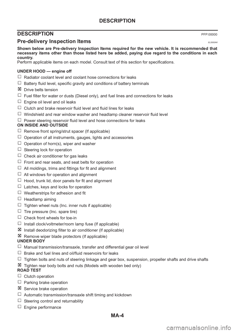
Shown below are Pre-delivery Inspection Items required for the new vehicle. It is recommended that
necessary items other than those listed here be added, paying due regard to the conditions in each
country.
Perform applicable items on each model. Consult text of this section for specifications.
UNDER HOOD — engine off
Radiator coolant level and coolant hose connections for leaks
Battery fluid level, specific gravity and conditions of battery terminals
Drive belts tension
Fuel filter for water or dusts (Diesel only), and fuel lines and connections for leaks
Engine oil level and oil leaks
Clutch and brake reservoir fluid level and fluid lines for leaks
Windshield and rear window washer and headlamp cleaner reservoir fluid level
Power steering reservoir fluid level and hose connections for leaks
ON INSIDE AND OUTSIDE
Remove front spring/strut spacer (If applicable)
Operation of all instruments, gauges, lights and accessories
Operation of horn(s), wiper and washer
Steering lock for operation
Check air conditioner for gas leaks
Front and rear seats, and seat belts for operation
All moldings, trims and fittings for fit and alignment
All windows for operation and alignment
Hood, trunk lid, door panels for fit and alignment
Latches, keys and locks for operation
Weatherstrips for adhesion and fit
Headlamp aiming
Tighten wheel nuts (Inc. inner nuts if applicable)
Tire pressure (Inc. spare tire)
Check front wheels for toe-in
Install clock/voltmeter/room lamp fuse (If applicable)
Install deodorizing filter to air conditioner (If applicable)
Remove wiper blade protectors (If applicable)
UNDER BODY
Manual transmission/transaxle, transfer and differential gear oil level
Brake and fuel lines and oil/fluid reservoirs for leaks
Tighten bolts and nuts of steering linkage and gear box, suspension, propeller shafts and drive shafts
Tighten rear body bolts and nuts (Models with wooden bed only)
ROAD TEST
Clutch operation
Parking brake operation
Service brake operation
Automatic transmission/transaxle shift timing and kickdown
Steering control and returnability
Engine performance
Page 3785 of 3833

DESCRIPTION
MA-5
C
D
E
F
G
H
I
J
K
MA
B
MA
Squeaks and rattles
ENGINE OPERATING AND HOT
Adjust idle speed
Automatic transmission/transaxle fluid level
Engine idling and stop knob operation (Diesel only)
FINAL INSPECTION
Install necessary parts (outside mirror, wheel covers, seat belts, mat, carpet or mud flaps)
Inspect for interior and exterior metal and paint damage
Check for spare tire, jack, tools (wheel chock), and literature
Wash, clean interior and exterior
: Not applicable to this model