Page 913 of 1306

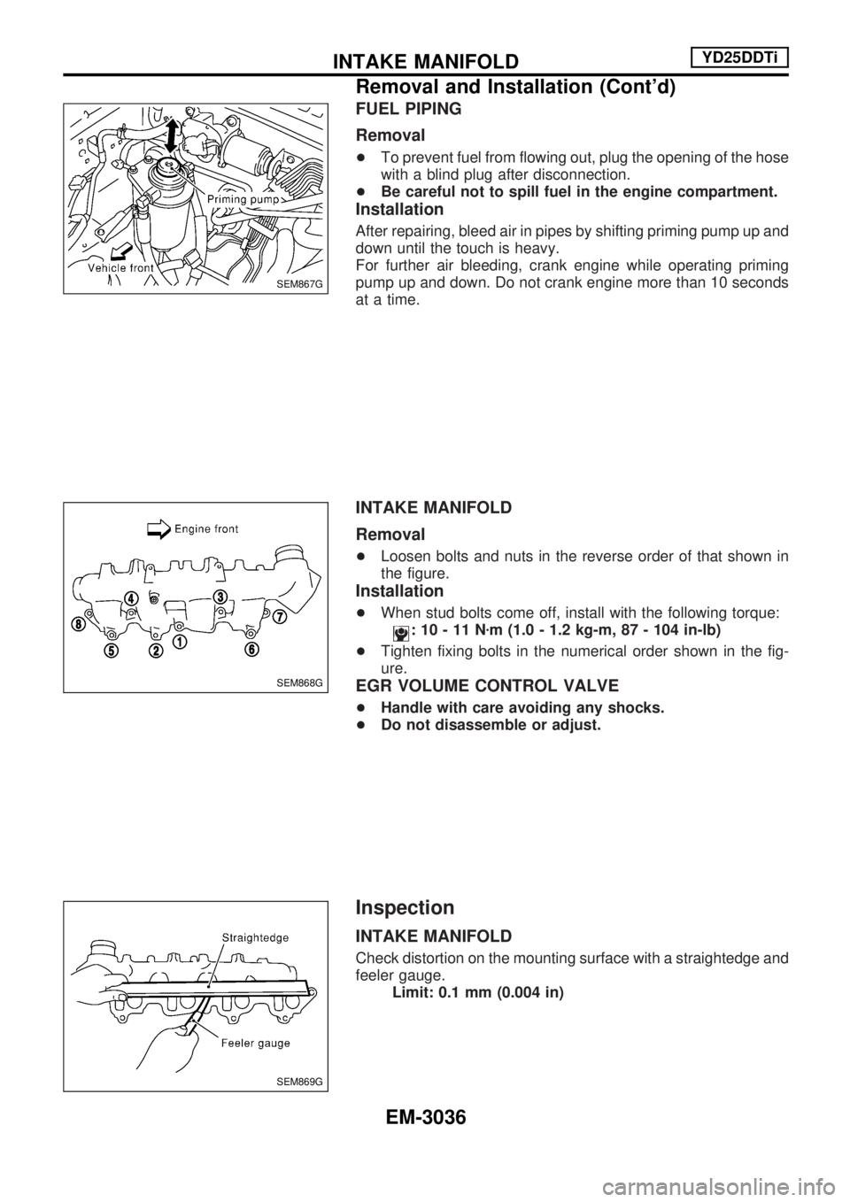
FUEL PIPING
Removal
+To prevent fuel from flowing out, plug the opening of the hose
with a blind plug after disconnection.
+Be careful not to spill fuel in the engine compartment.
Installation
After repairing, bleed air in pipes by shifting priming pump up and
down until the touch is heavy.
For further air bleeding, crank engine while operating priming
pump up and down. Do not crank engine more than 10 seconds
at a time.
INTAKE MANIFOLD
Removal
+Loosen bolts and nuts in the reverse order of that shown in
the figure.
Installation
+When stud bolts come off, install with the following torque:
:10-11Nzm (1.0 - 1.2 kg-m, 87 - 104 in-lb)
+Tighten fixing bolts in the numerical order shown in the fig-
ure.
EGR VOLUME CONTROL VALVE
+Handle with care avoiding any shocks.
+Do not disassemble or adjust.
Inspection
INTAKE MANIFOLD
Check distortion on the mounting surface with a straightedge and
feeler gauge.
Limit: 0.1 mm (0.004 in)
SEM867G
SEM868G
SEM869G
INTAKE MANIFOLDYD25DDTi
Removal and Installation (Cont'd)
EM-3036
Page 915 of 1306
Insulator mounting bolt:
Washer bolt (silver or yellow)
GUSSET
Installation
Pushing gussets against the oil pan and the catalyst, temporarily
tighten the mounting bolt. And then tighten it to the specified
torque.
CATALYSTYD25DDTi
Removal and Installation (Cont'd)
EM-3038
Page 917 of 1306
EXHAUST MANIFOLD AND TURBOCHARGER
Removal
+Loosen exhaust manifold mounting nuts in the reverse order
specified in the figure.
+After removing exhaust manifold, catalyst and turbocharger
assembly is pulled out.
CAUTION:
Be careful not to deform each turbocharger piping when
pulling out the assembly.
Installation
+When a stud bolt is removed, tighten it to the following
torque:
: 12.7 - 16.7 Nzm (1.3 - 1.7 kg-m, 10 - 12 ft-lb)
+Tighten the exhaust manifold mounting nuts in the following
procedure:
a) Tighten the nuts in the order specified in the figure.
b) Re-tighten the nuts 1 to 4.
EXHAUST MANIFOLD GASKET
Installation
Install the gasket so that the alignment protrusion faces the No.
4 port.
SEM872G
EXHAUST MANIFOLD, TURBOCHARGERYD25DDTi
Removal and Installation (Cont'd)
EM-3040
Page 918 of 1306
Disassembly and Assembly
1. Exhaust manifold
2. Gasket3. Turbocharger 4. Oil inlet tube
TURBOCHARGER
Disassembly
After applying penetration lubricant (Lucen, etc.) to the mounting
nuts, check for the penetration of the lubricant, and then loosen
the nuts to remove.
CAUTION:
Do not disassemble or adjust the turbocharger body.
Assembly
When a stud bolt is removed, tighten it to the following torque:
:24-27Nzm (2.4 - 2.8 kg-m, 18 - 20 ft-lb)
Inspection
Exhaust Manifold
Check the distortion on the mounting surface in the six directions
using a straightedge and a feeler gauge.
Limit: 0.3 mm (0.012 in)
SEM873G
JEM267G
EXHAUST MANIFOLD, TURBOCHARGERYD25DDTi
EM-3041
Page 922 of 1306
Removal and Installation
1. Oil filler cap 2. Rocker cover 3. Gasket
PREPARATIVE WORK
Remove the engine following parts.
+Charge air cooler
+Charge air cooler bracket
ROCKER COVER
Removal
Loosen bolts in the reverse order of that shown in the figure and
remove.
Installation
+Tighten bolts in the numerical order shown in the figure.
+Re-tighten to the same torque in the same order as above.
+Apply 3.0 mm (0.118 in) dia. of specified liquid gasket (Refer
to EM-3003, ªLiquid Gasket Application Procedureº.) on loca-
tions shown in the figure.
+Install in the reverse order of removal.
SEM880G
SEM884G
JEM248G
ROCKER COVERYD25DDTi
EM-3045
Page 927 of 1306

Amount of cylinder block resurfacing is ªBº.
The maximum limit:A+B=0.07 mm (0.0028 in)
After resurfacing cylinder head, check that camshaft rotates
freely by hand. If resistance is felt, cylinder head must be
replaced.
Nominal cylinder head height:
153.9 - 154.1 mm (6.059 - 6.067 in)
CAMSHAFT VISUAL CHECK
Check camshaft for scratches, seizure and wear.
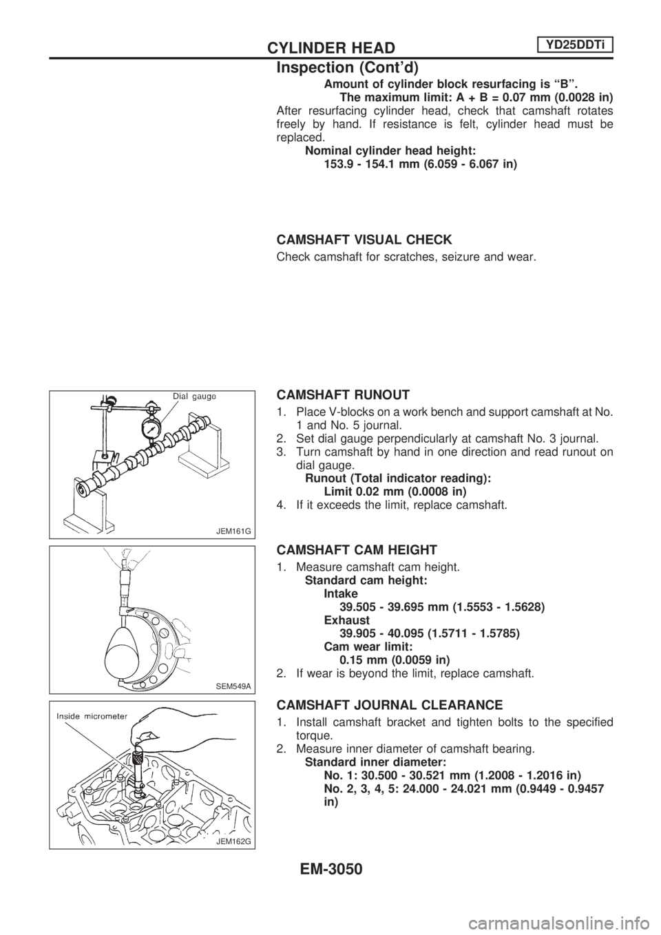
CAMSHAFT RUNOUT
1. Place V-blocks on a work bench and support camshaft at No.
1 and No. 5 journal.
2. Set dial gauge perpendicularly at camshaft No. 3 journal.
3. Turn camshaft by hand in one direction and read runout on
dial gauge.
Runout (Total indicator reading):
Limit 0.02 mm (0.0008 in)
4. If it exceeds the limit, replace camshaft.
CAMSHAFT CAM HEIGHT
1. Measure camshaft cam height.
Standard cam height:
Intake
39.505 - 39.695 mm (1.5553 - 1.5628)
Exhaust
39.905 - 40.095 (1.5711 - 1.5785)
Cam wear limit:
0.15 mm (0.0059 in)
2. If wear is beyond the limit, replace camshaft.
CAMSHAFT JOURNAL CLEARANCE
1. Install camshaft bracket and tighten bolts to the specified
torque.
2. Measure inner diameter of camshaft bearing.
Standard inner diameter:
No. 1: 30.500 - 30.521 mm (1.2008 - 1.2016 in)
No. 2, 3, 4, 5: 24.000 - 24.021 mm (0.9449 - 0.9457
in)
JEM161G
SEM549A
JEM162G
CYLINDER HEADYD25DDTi
Inspection (Cont'd)
EM-3050
Page 940 of 1306

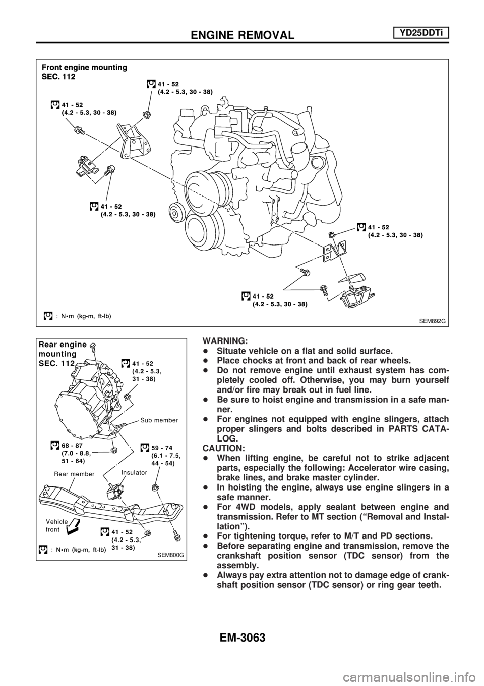
WARNING:
+Situate vehicle on a flat and solid surface.
+Place chocks at front and back of rear wheels.
+Do not remove engine until exhaust system has com-
pletely cooled off. Otherwise, you may burn yourself
and/or fire may break out in fuel line.
+Be sure to hoist engine and transmission in a safe man-
ner.
+For engines not equipped with engine slingers, attach
proper slingers and bolts described in PARTS CATA-
LOG.
CAUTION:
+When lifting engine, be careful not to strike adjacent
parts, especially the following: Accelerator wire casing,
brake lines, and brake master cylinder.
+In hoisting the engine, always use engine slingers in a
safe manner.
+For 4WD models, apply sealant between engine and
transmission. Refer to MT section (ªRemoval and Instal-
lationº).
+For tightening torque, refer to M/T and PD sections.
+Before separating engine and transmission, remove the
crankshaft position sensor (TDC sensor) from the
assembly.
+Always pay extra attention not to damage edge of crank-
shaft position sensor (TDC sensor) or ring gear teeth.
SEM892G
SEM800G
ENGINE REMOVALYD25DDTi
EM-3063
Page 952 of 1306

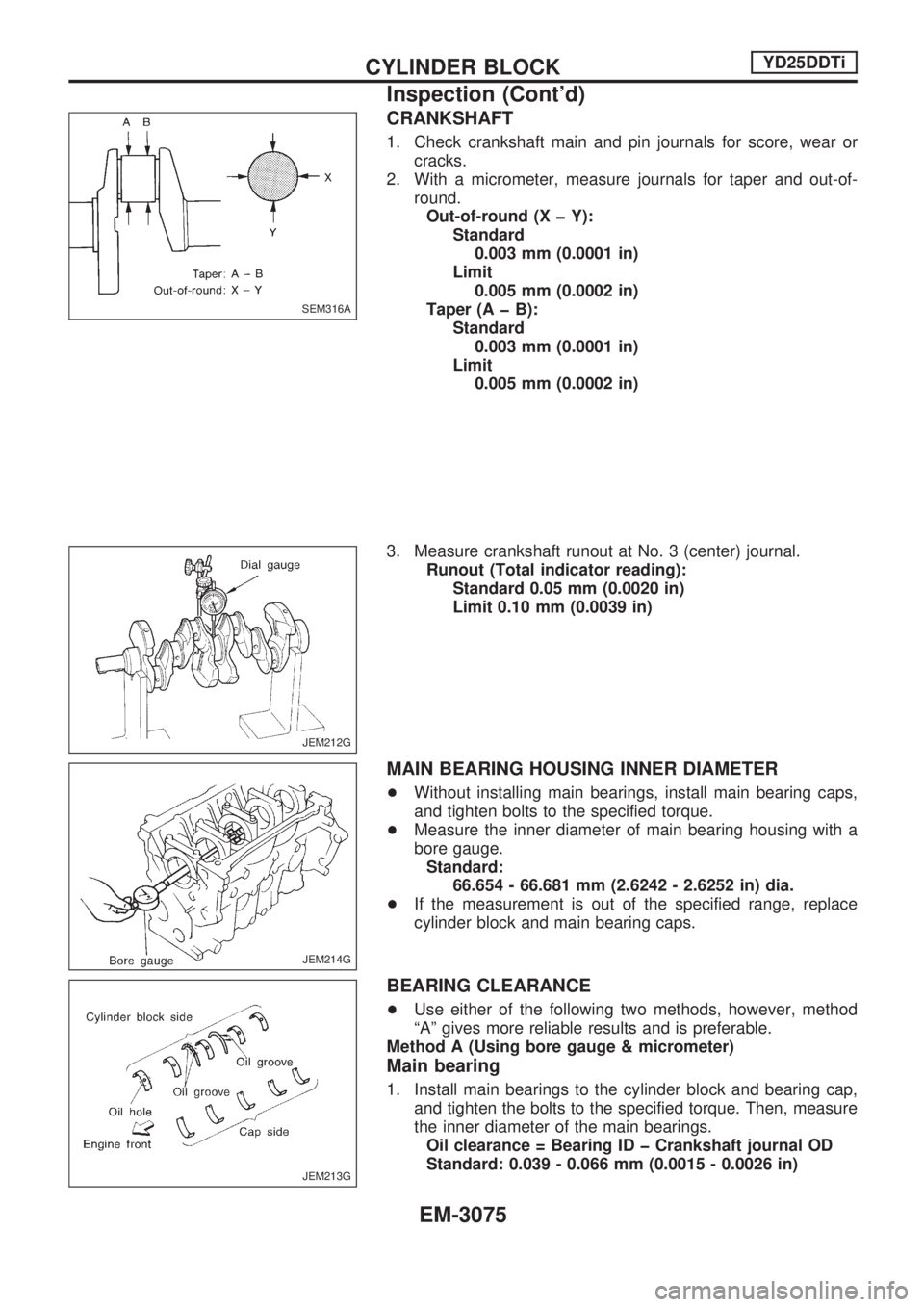
CRANKSHAFT
1. Check crankshaft main and pin journals for score, wear or
cracks.
2. With a micrometer, measure journals for taper and out-of-
round.
Out-of-round (X þ Y):
Standard
0.003 mm (0.0001 in)
Limit
0.005 mm (0.0002 in)
Taper (A þ B):
Standard
0.003 mm (0.0001 in)
Limit
0.005 mm (0.0002 in)
3. Measure crankshaft runout at No. 3 (center) journal.
Runout (Total indicator reading):
Standard 0.05 mm (0.0020 in)
Limit 0.10 mm (0.0039 in)
MAIN BEARING HOUSING INNER DIAMETER
+Without installing main bearings, install main bearing caps,
and tighten bolts to the specified torque.
+Measure the inner diameter of main bearing housing with a
bore gauge.
Standard:
66.654 - 66.681 mm (2.6242 - 2.6252 in) dia.
+If the measurement is out of the specified range, replace
cylinder block and main bearing caps.
BEARING CLEARANCE
+Use either of the following two methods, however, method
ªAº gives more reliable results and is preferable.
Method A (Using bore gauge & micrometer)
Main bearing
1. Install main bearings to the cylinder block and bearing cap,
and tighten the bolts to the specified torque. Then, measure
the inner diameter of the main bearings.
Oil clearance = Bearing ID þ Crankshaft journal OD
Standard: 0.039 - 0.066 mm (0.0015 - 0.0026 in)
SEM316A
JEM212G
JEM214G
JEM213G
CYLINDER BLOCKYD25DDTi
Inspection (Cont'd)
EM-3075