2001 NISSAN PICK-UP torque
[x] Cancel search: torquePage 954 of 1306
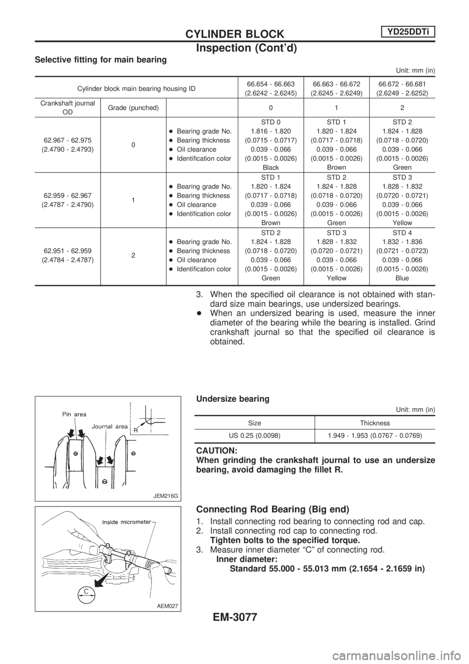
Selective fitting for main bearing
Unit: mm (in)
Cylinder block main bearing housing ID66.654 - 66.663
(2.6242 - 2.6245)66.663 - 66.672
(2.6245 - 2.6249)66.672 - 66.681
(2.6249 - 2.6252)
Crankshaft journal
ODGrade (punched) 0 1 2
62.967 - 62.975
(2.4790 - 2.4793)0+Bearing grade No.
+Bearing thickness
+Oil clearance
+Identification colorSTD 0
1.816 - 1.820
(0.0715 - 0.0717)
0.039 - 0.066
(0.0015 - 0.0026)
BlackSTD 1
1.820 - 1.824
(0.0717 - 0.0718)
0.039 - 0.066
(0.0015 - 0.0026)
BrownSTD 2
1.824 - 1.828
(0.0718 - 0.0720)
0.039 - 0.066
(0.0015 - 0.0026)
Green
62.959 - 62.967
(2.4787 - 2.4790)1+Bearing grade No.
+Bearing thickness
+Oil clearance
+Identification colorSTD 1
1.820 - 1.824
(0.0717 - 0.0718)
0.039 - 0.066
(0.0015 - 0.0026)
BrownSTD 2
1.824 - 1.828
(0.0718 - 0.0720)
0.039 - 0.066
(0.0015 - 0.0026)
GreenSTD 3
1.828 - 1.832
(0.0720 - 0.0721)
0.039 - 0.066
(0.0015 - 0.0026)
Yellow
62.951 - 62.959
(2.4784 - 2.4787)2+Bearing grade No.
+Bearing thickness
+Oil clearance
+Identification colorSTD 2
1.824 - 1.828
(0.0718 - 0.0720)
0.039 - 0.066
(0.0015 - 0.0026)
GreenSTD 3
1.828 - 1.832
(0.0720 - 0.0721)
0.039 - 0.066
(0.0015 - 0.0026)
YellowSTD 4
1.832 - 1.836
(0.0721 - 0.0723)
0.039 - 0.066
(0.0015 - 0.0026)
Blue
3. When the specified oil clearance is not obtained with stan-
dard size main bearings, use undersized bearings.
+When an undersized bearing is used, measure the inner
diameter of the bearing while the bearing is installed. Grind
crankshaft journal so that the specified oil clearance is
obtained.
Undersize bearing
Unit: mm (in)
Size Thickness
US 0.25 (0.0098) 1.949 - 1.953 (0.0767 - 0.0769)
CAUTION:
When grinding the crankshaft journal to use an undersize
bearing, avoid damaging the fillet R.
Connecting Rod Bearing (Big end)
1. Install connecting rod bearing to connecting rod and cap.
2. Install connecting rod cap to connecting rod.
Tighten bolts to the specified torque.
3. Measure inner diameter ªCº of connecting rod.
Inner diameter:
Standard 55.000 - 55.013 mm (2.1654 - 2.1659 in)
JEM216G
AEM027
CYLINDER BLOCKYD25DDTi
Inspection (Cont'd)
EM-3077
Page 956 of 1306
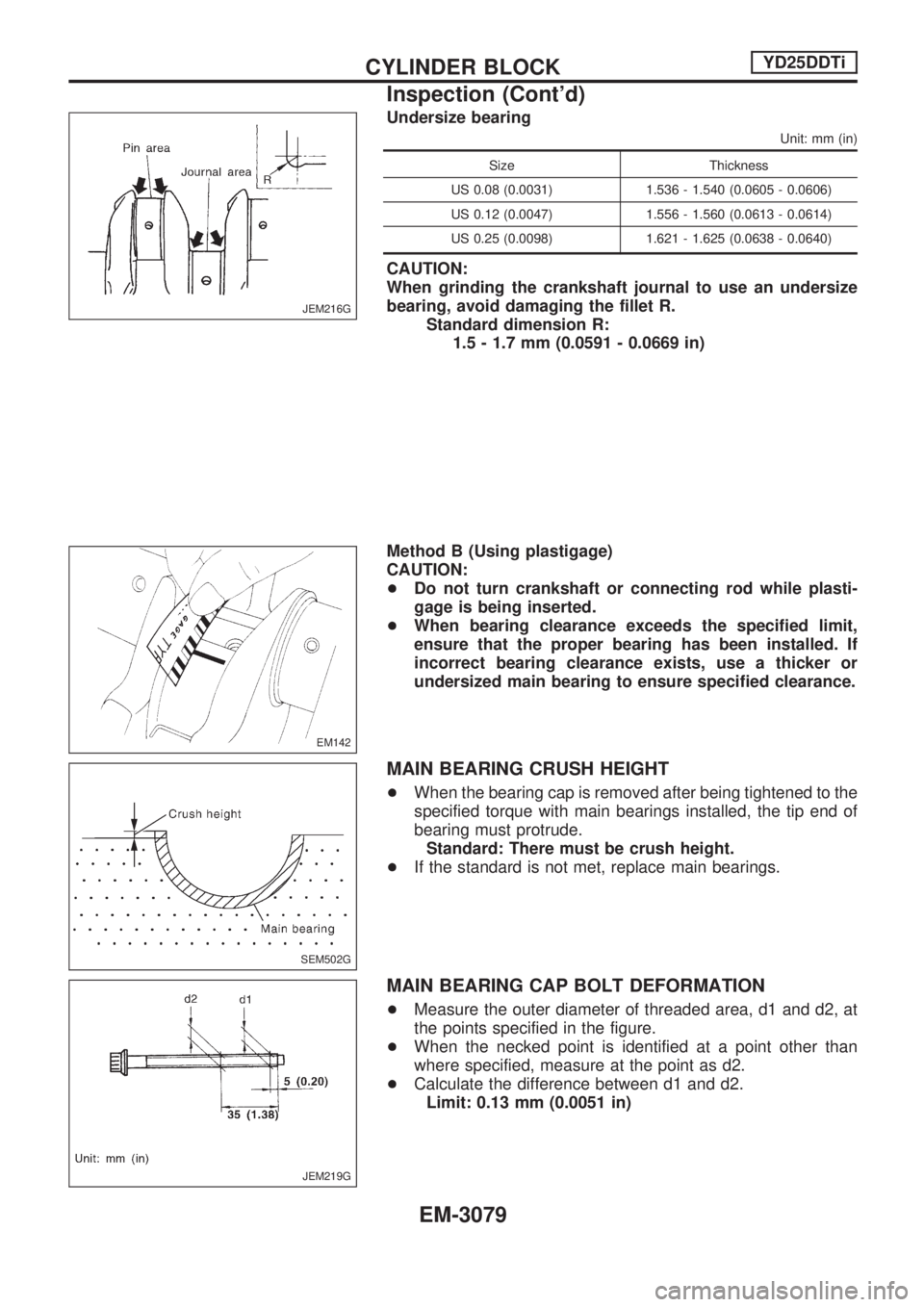
Undersize bearing
Unit: mm (in)
Size Thickness
US 0.08 (0.0031) 1.536 - 1.540 (0.0605 - 0.0606)
US 0.12 (0.0047) 1.556 - 1.560 (0.0613 - 0.0614)
US 0.25 (0.0098) 1.621 - 1.625 (0.0638 - 0.0640)
CAUTION:
When grinding the crankshaft journal to use an undersize
bearing, avoid damaging the fillet R.
Standard dimension R:
1.5 - 1.7 mm (0.0591 - 0.0669 in)
Method B (Using plastigage)
CAUTION:
+Do not turn crankshaft or connecting rod while plasti-
gage is being inserted.
+When bearing clearance exceeds the specified limit,
ensure that the proper bearing has been installed. If
incorrect bearing clearance exists, use a thicker or
undersized main bearing to ensure specified clearance.
MAIN BEARING CRUSH HEIGHT
+When the bearing cap is removed after being tightened to the
specified torque with main bearings installed, the tip end of
bearing must protrude.
Standard: There must be crush height.
+If the standard is not met, replace main bearings.
MAIN BEARING CAP BOLT DEFORMATION
+Measure the outer diameter of threaded area, d1 and d2, at
the points specified in the figure.
+When the necked point is identified at a point other than
where specified, measure at the point as d2.
+Calculate the difference between d1 and d2.
Limit: 0.13 mm (0.0051 in)
JEM216G
EM142
SEM502G
JEM219G
CYLINDER BLOCKYD25DDTi
Inspection (Cont'd)
EM-3079
Page 960 of 1306
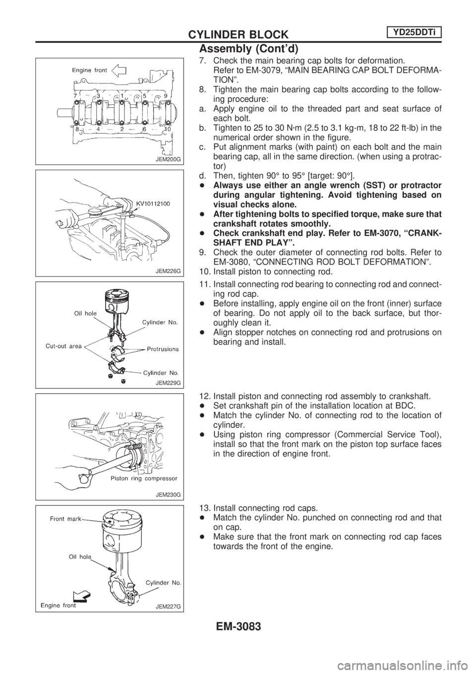
7. Check the main bearing cap bolts for deformation.
Refer to EM-3079, ªMAIN BEARING CAP BOLT DEFORMA-
TIONº.
8. Tighten the main bearing cap bolts according to the follow-
ing procedure:
a. Apply engine oil to the threaded part and seat surface of
each bolt.
b. Tighten to 25 to 30 Nzm (2.5 to 3.1 kg-m, 18 to 22 ft-lb) in the
numerical order shown in the figure.
c. Put alignment marks (with paint) on each bolt and the main
bearing cap, all in the same direction. (when using a protrac-
tor)
d. Then, tighten 90É to 95É [target: 90É].
+Always use either an angle wrench (SST) or protractor
during angular tightening. Avoid tightening based on
visual checks alone.
+After tightening bolts to specified torque, make sure that
crankshaft rotates smoothly.
+Check crankshaft end play. Refer to EM-3070, ªCRANK-
SHAFT END PLAYº.
9. Check the outer diameter of connecting rod bolts. Refer to
EM-3080, ªCONNECTING ROD BOLT DEFORMATIONº.
10. Install piston to connecting rod.
11. Install connecting rod bearing to connecting rod and connect-
ing rod cap.
+Before installing, apply engine oil on the front (inner) surface
of bearing. Do not apply oil to the back surface, but thor-
oughly clean it.
+Align stopper notches on connecting rod and protrusions on
bearing and install.
12. Install piston and connecting rod assembly to crankshaft.
+Set crankshaft pin of the installation location at BDC.
+Match the cylinder No. of connecting rod to the location of
cylinder.
+Using piston ring compressor (Commercial Service Tool),
install so that the front mark on the piston top surface faces
in the direction of engine front.
13. Install connecting rod caps.
+Match the cylinder No. punched on connecting rod and that
on cap.
+Make sure that the front mark on connecting rod cap faces
towards the front of the engine.
JEM200G
JEM226G
JEM229G
JEM230G
JEM227G
CYLINDER BLOCKYD25DDTi
Assembly (Cont'd)
EM-3083
Page 961 of 1306
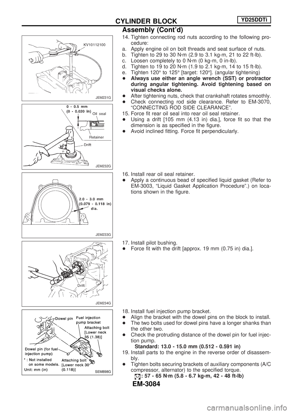
14. Tighten connecting rod nuts according to the following pro-
cedure:
a. Apply engine oil on bolt threads and seat surface of nuts.
b. Tighten to 29 to 30 Nzm (2.9 to 3.1 kg-m, 21 to 22 ft-lb).
c. Loosen completely to 0 Nzm (0 kg-m, 0 in-lb).
d. Tighten to 19 to 20 Nzm (1.9 to 2.1 kg-m, 14 to 15 ft-lb).
e. Tighten 120É to 125É [target: 120É]. (angular tightening)
+Always use either an angle wrench (SST) or protractor
during angular tightening. Avoid tightening based on
visual checks alone.
+After tightening nuts, check that crankshaft rotates smoothly.
+Check connecting rod side clearance. Refer to EM-3070,
ªCONNECTING ROD SIDE CLEARANCEº.
15. Force fit rear oil seal into rear oil seal retainer.
+Using a drift [105 mm (4.13 in) dia.], force fit so that the
dimension is as specified in the figure.
+Avoid inclined fitting. Force fit perpendicularly.
16. Install rear oil seal retainer.
+Apply a continuous bead of specified liquid gasket (Refer to
EM-3003, ªLiquid Gasket Application Procedureº.) on loca-
tions shown in the figure.
17. Install pilot bushing.
+Force fit with the drift [approx. 19 mm (0.75 in) dia.].
18. Install fuel injection pump bracket.
+Align the bracket with the dowel pins on the block to install.
+The two bolts used for dowel pins have a longer shanks than
the other two.
+Check the protruding distance of the dowel pin for fuel injec-
tion pump.
Standard: 13.0 - 15.0 mm (0.512 - 0.591 in)
19. Install parts to the engine in the reverse order of disassem-
bly.
+Tighten bolts securing brackets of auxiliary components (A/C
compressor, alternator) to the specified torque.
:57-65Nzm (5.8 - 6.7 kg-m, 42 - 48 ft-lb)
JEM231G
JEM232G
JEM233G
JEM234G
SEM898G
CYLINDER BLOCKYD25DDTi
Assembly (Cont'd)
EM-3084
Page 1021 of 1306
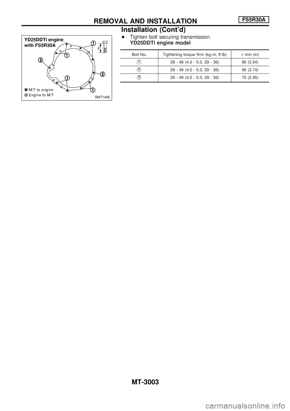
+Tighten bolt securing transmission.
YD25DDTi engine model
Bolt No. Tightening torque Nzm (kg-m, ft-lb)!mm (in)
V139 - 49 (4.0 - 5.0, 29 - 36) 90 (3.54)
V239 - 49 (4.0 - 5.0, 29 - 36) 95 (3.74)
V339 - 49 (4.0 - 5.0, 29 - 36) 75 (2.95)
SMT144E
REMOVAL AND INSTALLATIONFS5R30A
Installation (Cont'd)
MT-3003
Page 1023 of 1306
MAINTENANCE
SECTION
MA
MODIFICATION NOTICE:
+KA24DE engine information has been added. Refer to the Service Manual of D22 Supplement-II (SM9E-
D22BE0E) for the maintenance procedure not included here.
+YD25DDTi engine has been added.
CONTENTS
PERIODIC MAINTENANCE................................ 3002
Maintenance Schedule for Petrol Engines
(Annual Mileage < 30,000 km/year) ................ 3002
Maintenance Schedule for Diesel Engines
(Annual Mileage < 30,000 km/year) ................ 3003
Maintenance Under Severe Driving Conditions
(Annual Driving Distance < 30,000 km/year)... 3004
Maintenance Schedule for Petrol Engines
(Annual Mileage > 30,000 km/year) ................ 3005
Maintenance Schedule for Diesel Engines
(Annual Mileage > 30,000 km/year) ................ 3006
Maintenance Under Severe Driving Conditions
(Annual Driving Distance > 30,000 km/year)... 3007
RECOMMENDED FLUIDS AND
LUBRICANTS...................................................... 3008
Fluids and Lubricants....................................... 3008
SAE Viscosity Number..................................... 3009
KA24DE
ENGINE MAINTENANCE.................................... 3010Changing Air Cleaner Filter ............................. 3010
Changing Positive Crankcase Ventilation
(PCV) Filter ...................................................... 3010
YD25DDTi
ENGINE MAINTENANCE.................................... 3011
Checking Tightening Torque............................ 3011
Checking Drive Belts ....................................... 3011
Changing Engine Oil ........................................ 3012
Changing Oil Filter ........................................... 3013
Changing Engine Coolant ................................ 3014
Checking Cooling System................................ 3016
Checking and Replacing Fuel Filter and
Draining Water ................................................. 3018
Checking Fuel Lines ........................................ 3019
Cleaning and Replacing Air Cleaner Filter ...... 3019
Checking Cyclone Pre-air Cleaner .................. 3019
SERVICE DATA AND SPECIFICATIONS
(SDS).................................................................... 3020
Engine Maintenance ........................................ 3020
MA
Page 1033 of 1306
Checking Tightening Torque
Checking should be performed while engine is cold.
MANIFOLD BOLTS AND NUTS
Intake
: 19.7 - 23.5 Nzm (2.0 - 2.3 kg-m, 15 - 17 ft-lb)
Exhaust
: 28.5 - 33.3 Nzm (2.9 - 3.3 kg-m, 21 - 24 ft-lb)
EXHAUST TUBE NUTS
: 41 - 48.0 Nzm (4.1 - 4.9 kg-m, 30 - 35 ft-lb)
Checking Drive Belts
INSPECTION
+Before inspecting the engine, make sure the engine has
cooled down; wait approximately 30 minutes after the engine
has been stopped.
+Visually inspect all belts for wear, damage, or cracks on
contacting surfaces and edge areas.
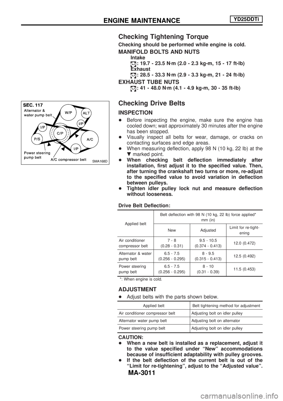
+When measuring deflection, apply 98 N (10 kg, 22 lb) at the
.marked point.
+When checking belt deflection immediately after
installation, first adjust it to the specified value. Then,
after turning the crankshaft two turns or more, re-adjust
to the specified value to avoid variation in deflection
between pulleys.
+Tighten idler pulley lock nut and measure deflection
without looseness.
Drive Belt Deflection:
Applied beltBelt deflection with 98 N (10 kg, 22 lb) force applied*
mm (in)
New AdjustedLimit for re-tight-
ening
Air conditioner
compressor belt7-8
(0.28 - 0.31)9.5 - 10.5
(0.374 - 0.413)12.0 (0.472)
Alternator & water
pump belt6.5 - 7.5
(0.256 - 0.295)8 - 9.5
(0.315 - 0.413)12.5 (0.492)
Power steering
pump belt6.5 - 7.5
(0.256 - 0.295)8-10
(0.31 - 0.39)11.5 (0.453)
*: When engine is cold.
ADJUSTMENT
+Adjust belts with the parts shown below.
Applied belt Belt tightening method for adjustment
Air conditioner compressor belt Adjusting bolt on idler pulley
Alternator water pump belt Adjusting bolt on alternator
Power steering pump belt Adjusting bolt on idler pulley
CAUTION:
+When a new belt is installed as a replacement, adjust it
to the value specified under ªNewº accommodations
because of insufficient adaptability with pulley grooves.
+If the belt deflection of the current belt is out of the
ªLimit for re-tighteningº, adjust to the ªAdjusted valueº.
SMA168D
ENGINE MAINTENANCEYD25DDTi
MA-3011
Page 1064 of 1306
Injection nozzle ........................... EC-3415, 3416
Injector removal and installation ........... EC-3034
Intake air temperature
sensor ................. EC-3160, 3193, 3503, 3504
Intake manifold ..................................... EM-3008
Interior lamp ........................................... EL-3054
K
KS - Wiring diagram ............................. EC-3261
Keyless entry system - See Multi-re-
mote control system .......................... EL-3136
Knock sensor (KS) ...................... EC-3260, 3261
L
License lampEL148Parking lamp .......... EL-3039
Liquid gasket application ...................... EM-3003
Location of electrical units ..................... EL-3163
Lubricants ............................................. MA-3008
Lubrication circuit (engine) .................... LC-3003
M
M/T removal and installation ................ MT-3002
MAFS - Wiring diagram .............. EC-3146, 3154
MAIN - Wiring diagram ..... EC-3124, 3470, 3471
METER - Wiring diagram ...................... EL-3062
MIL & Data link connectors circuit ........ EC-3396
MIL/DL - Wiring diagram .. EC-3396, 3646, 3647
MIRROR - Wiring diagram .................... EL-3116
MULTI - Wiring diagram ........................ EL-3137
Main gear (Transfer) .............................. TF-3004
Mainshaft (Transfer) .............................. TF-3004
Maintenance (engine) ................. MA-3010, 3011
Malfunction indicator lamp
(MIL) ........................................ EC-3429, 3430
Manifold tightening torque (intake &
exhaust) ............................................ MA-3011
Mass air flow sensor
(MAFS) .................... DT-3143, EC-3143, 3151
Meter ...................................................... EL-3056
Misfire .................................................... EC-3251
Model variation ....................................... GI-3004
Mud guard - See Exterior ...................... BT-3006
Multi-remote control system .................. EL-3136
Multiport fuel injection (MFI) system ..... EC-3024
N
NATS (Nissan Anti-theft System) .......... EL-3143
NATS - Wiring diagram ......................... EL-3146
Neutral position switch .......................... EC-3355
O
Oil change (capacity) ............................ MA-3008
Oil cooler (engine) ................................. LC-3006
Oil pan (engine) .................................... EM-3015
Oil pressure (engine) ............................. LC-3004
Oil pump (engine) .................................. LC-3004
Oil pump regulator valve (engine) ......... LC-3005
On board diagnostic
system ........................... EC-3049, 3428, 3429
P
P/ANT - Wiring diagram ........................ EL-3115
PCV (positive crankcase
ventilation) ..................... EC-3032, 3414, 3415
PCV filter replacement ......................... MA-3010
PGC/V - Wiring diagram ....................... EC-3286
PNP/SW - Wiring diagram .................... EC-3358
POWER - Wiring diagram ..................... EL-3006
PST/SW - Wiring diagram .................... EC-3386
Park/Neutral position
switch ............................ EC-3355, 3633, 3634
Parking lamp .......................................... EL-3039
Piston assembly ................................... EM-3081
Piston pin inspection ............................ EM-3071
Piston ring inspection ........................... EM-3071
Piston to bore clearance ...................... EM-3073
Power door mirror .................................. EL-3116
Power steering oil pressure switch ....... EC-3385
Power supply routing ............................. EL-3005
Power transistor & ignition coil ............. EC-3361
Power window ....................................... EL-3120
Priming pump .............................. EC-3444, 3445
Q
Quick-glow system ...................... EC-3621, 3622
R
R/FOG - Wiring diagram ....................... EL-3045
ROOM/L - Wiring diagram ..................... EL-3054
Radiator fan - See Cooling fan ............. LC-3016
Radiator ................................................. LC-3015
Rear case (Transfer) ............................. TF-3003
Rear fog lamp ........................................ EL-3045
Rear window defogger .......................... EL-3112
Refrigerant connection precaution ........ HA-3002
Refrigerant lines .................................... HA-3030
Road wheel size ..................................... GI-3007
Room lamp ............................................ EL-3054
ALPHABETICAL INDEX
IDX-3004