2001 NISSAN ALMERA TINO fuel
[x] Cancel search: fuelPage 514 of 3051
![NISSAN ALMERA TINO 2001 Service Repair Manual Monitored item [Unit]ECM
input
signalsMain
signalsDescription Remarks
IDL A/V LEARN+Display the condition of idle air volume learn-
ing
YET ... Idle air volume learning has not been
performed yet.
CMP NISSAN ALMERA TINO 2001 Service Repair Manual Monitored item [Unit]ECM
input
signalsMain
signalsDescription Remarks
IDL A/V LEARN+Display the condition of idle air volume learn-
ing
YET ... Idle air volume learning has not been
performed yet.
CMP](/manual-img/5/57352/w960_57352-513.png)
Monitored item [Unit]ECM
input
signalsMain
signalsDescription Remarks
IDL A/V LEARN+Display the condition of idle air volume learn-
ing
YET ... Idle air volume learning has not been
performed yet.
CMPLT ... Idle air volume learning has
already been performed successfully.
INCMP ... Idle air volume learning has not
been performed successfully.
TRVL AFTER MIL
[km] or [Mile]+Distance traveled while MI is activated
VOLTAGE [V]+Voltage measured by the voltage probe.
PULSE
[msec] or [Hz] or [%]+Pulse width, frequency or duty cycle mea-
sured by the pulse probe.+Only ª#º is displayed if item is
unable to be measured.
+Figures with ª#ºs are temporary
ones. They are the same figures as
an actual piece of data which was
just previously measured.
NOTE:
Any monitored item that does not match the vehicle being diagnosed is deleted from the display automatically.
DATA MONITOR (SPEC) MODENLEC0034S11
Monitored item [Unit]ECM
input
signalsMain
signalsDescription Remarks
MAS A/F SE-B1 [V]jj+The signal voltage of the mass air flow sen-
sor specification is displayed.+When the engine is running, specifi-
cation range is indicated.
B/FUEL SCHDL
[msec]+ªBase fuel scheduleº indicates the fuel injec-
tion pulse width programmed into ECM, prior
to any learned on board correction.+When the engine is running, specifi-
cation range is indicated.
A/F ALPHA-B1 [%]j+Indicates the mean value of the air-fuel ratio
feedback correction factor per cycle.+When the engine is running, specifi-
cation range is indicated.
+This data also includes the data for
the air-fuel ratio learning control.
NOTE:
Any monitored item that does not match the vehicle being diagnosed is deleted from the display automatically.
ACTIVE TEST MODENLEC0034S07
TEST ITEM CONDITION JUDGEMENT CHECK ITEM (REMEDY)
FUEL INJEC-
TION+Engine: Return to the original
trouble condition
+Change the amount of fuel injec-
tion using CONSULT-II.If trouble symptom disappears, see
CHECK ITEM.+Harness and connector
+Fuel injectors
+Heated oxygen sensor 1 (front)
IGNITION TIM-
ING+Engine: Return to the original
trouble condition
+Timing light: Set
+Retard the ignition timing using
CONSULT-II.If trouble symptom disappears, see
CHECK ITEM.+ªIdle Air Volume Leaningº (Refer
to EC-57.)
+Camshaft position sensor
(PHASE)
+Crankshaft position sensor
(POS)
+Engine component parts and
installing conditions
ON BOARD DIAGNOSTIC SYSTEM DESCRIPTIONQG18DE
CONSULT-II (Cont'd)
EC-89
Page 515 of 3051
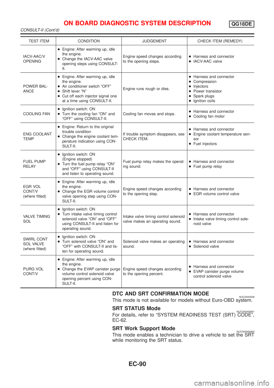
TEST ITEM CONDITION JUDGEMENT CHECK ITEM (REMEDY)
IACV-AAC/V
OPENING+Engine: After warming up, idle
the engine.
+Change the IACV-AAC valve
opening steps using CONSULT-
II.Engine speed changes according
to the opening steps.+Harness and connector
+IACV-AAC valve
POWER BAL-
ANCE+Engine: After warming up, idle
the engine.
+Air conditioner switch ªOFFº
+Shift lever ªNº
+Cut off each injector signal one
at a time using CONSULT-II.Engine runs rough or dies.+Harness and connector
+Compression
+Injectors
+Power transistor
+Spark plugs
+Ignition coils
COOLING FAN+Ignition switch: ON
+Turn the cooling fan ªONº and
ªOFFº using CONSULT-II.Cooling fan moves and stops.+Harness and connector
+Cooling fan motor
ENG COOLANT
TEMP+Engine: Return to the original
trouble condition
+Change the engine coolant tem-
perature indication using CON-
SULT-II.If trouble symptom disappears, see
CHECK ITEM.+Harness and connector
+Engine coolant temperature sen-
sor
+Fuel injectors
FUEL PUMP
RELAY+Ignition switch: ON
(Engine stopped)
+Turn the fuel pump relay ªONº
and ªOFFº using CONSULT-II
and listen to operating sound.Fuel pump relay makes the operat-
ing sound.+Harness and connector
+Fuel pump relay
EGR VOL
CONT/V
(where fitted)+Engine: After warming up, idle
the engine.
+Change the EGR volume control
valve opening step using CON-
SULT-II.Engine speed changes according
to the opening step.+Harness and connector
+EGR volume control valve
VALVE TIMING
SOL+Ignition switch: ON
+Turn intake valve timing control
solenoid valve ªONº and ªOFFº
using CONSULT-II and listen for
operating sound.Intake valve timing control solenoid
valve makes an operating sound.+Harness and connector
+Intake valve timing control sole-
noid valve
SWIRL CONT
S O L VA LV E
(where fitted)+Ignition switch: ON
+Turn solenoid valve ªONº and
ªOFFº with CONSULT-II and lis-
ten for operating sound.Solenoid valve makes an operating
sound.+Harness and connector
+Solenoid valve
PURG VOL
CONT/V+Engine: After warming up, idle
the engine.
+Change the EVAP canister purge
volume control solenoid valve
opening percent using CON-
SULT-II.Engine speed changes according
to the opening percent.+Harness and connector
+EVAP canister purge volume
control solenoid valve
DTC AND SRT CONFIRMATION MODENLEC0034S08This mode is not available for models without Euro-OBD system.
SRT STATUS ModeNLEC0034S0801For details, refer to ªSYSTEM READINESS TEST (SRT) CODEº,
EC-62.
SRT Work Support ModeNLEC0034S0803This mode enables a technician to drive a vehicle to set the SRT
while monitoring the SRT status.
ON BOARD DIAGNOSTIC SYSTEM DESCRIPTIONQG18DE
CONSULT-II (Cont'd)
EC-90
Page 520 of 3051
MEF036D
SEF233G
SEF234G
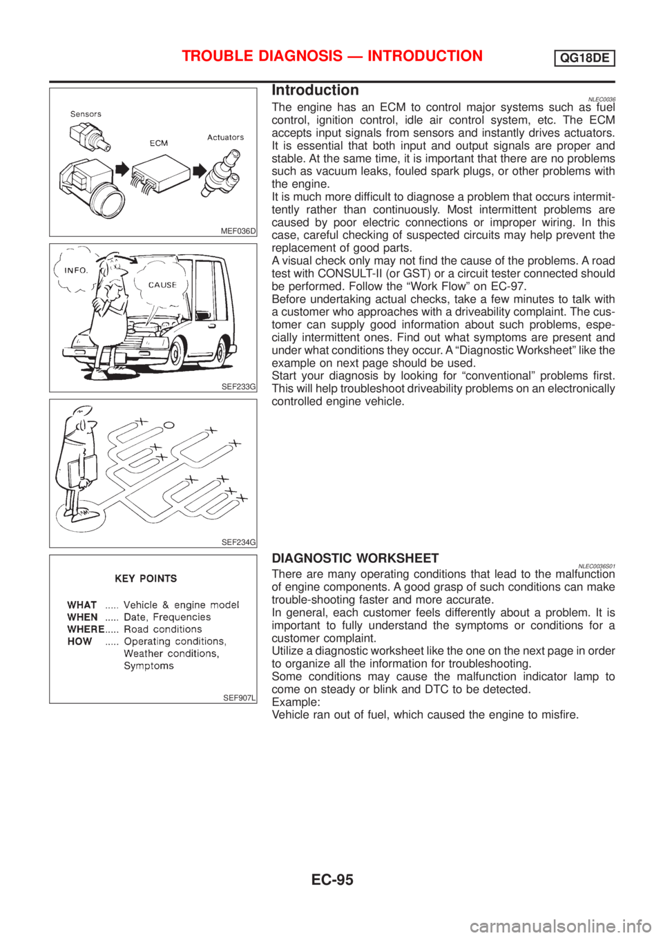
IntroductionNLEC0036The engine has an ECM to control major systems such as fuel
control, ignition control, idle air control system, etc. The ECM
accepts input signals from sensors and instantly drives actuators.
It is essential that both input and output signals are proper and
stable. At the same time, it is important that there are no problems
such as vacuum leaks, fouled spark plugs, or other problems with
the engine.
It is much more difficult to diagnose a problem that occurs intermit-
tently rather than continuously. Most intermittent problems are
caused by poor electric connections or improper wiring. In this
case, careful checking of suspected circuits may help prevent the
replacement of good parts.
A visual check only may not find the cause of the problems. A road
test with CONSULT-II (or GST) or a circuit tester connected should
be performed. Follow the ªWork Flowº on EC-97.
Before undertaking actual checks, take a few minutes to talk with
a customer who approaches with a driveability complaint. The cus-
tomer can supply good information about such problems, espe-
cially intermittent ones. Find out what symptoms are present and
under what conditions they occur. A ªDiagnostic Worksheetº like the
example on next page should be used.
Start your diagnosis by looking for ªconventionalº problems first.
This will help troubleshoot driveability problems on an electronically
controlled engine vehicle.
SEF907L
DIAGNOSTIC WORKSHEETNLEC0036S01There are many operating conditions that lead to the malfunction
of engine components. A good grasp of such conditions can make
trouble-shooting faster and more accurate.
In general, each customer feels differently about a problem. It is
important to fully understand the symptoms or conditions for a
customer complaint.
Utilize a diagnostic worksheet like the one on the next page in order
to organize all the information for troubleshooting.
Some conditions may cause the malfunction indicator lamp to
come on steady or blink and DTC to be detected.
Example:
Vehicle ran out of fuel, which caused the engine to misfire.
TROUBLE DIAGNOSIS Ð INTRODUCTIONQG18DE
EC-95
Page 547 of 3051
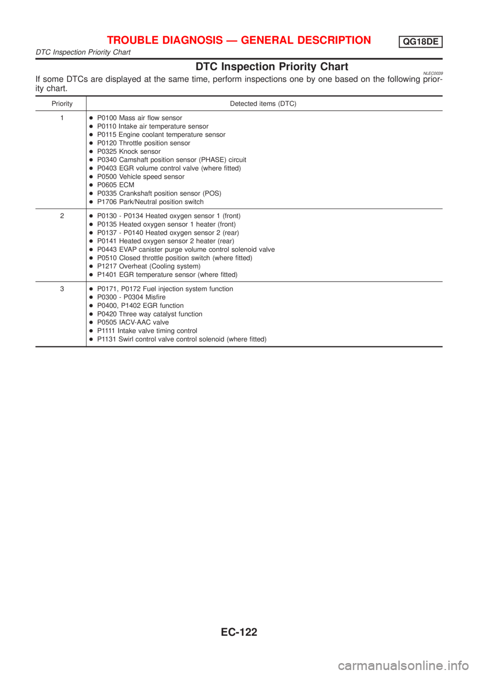
DTC Inspection Priority ChartNLEC0039If some DTCs are displayed at the same time, perform inspections one by one based on the following prior-
ity chart.
Priority Detected items (DTC)
1+P0100 Mass air flow sensor
+P0110 Intake air temperature sensor
+P0115 Engine coolant temperature sensor
+P0120 Throttle position sensor
+P0325 Knock sensor
+P0340 Camshaft position sensor (PHASE) circuit
+P0403 EGR volume control valve (where fitted)
+P0500 Vehicle speed sensor
+P0605 ECM
+P0335 Crankshaft position sensor (POS)
+P1706 Park/Neutral position switch
2+P0130 - P0134 Heated oxygen sensor 1 (front)
+P0135 Heated oxygen sensor 1 heater (front)
+P0137 - P0140 Heated oxygen sensor 2 (rear)
+P0141 Heated oxygen sensor 2 heater (rear)
+P0443 EVAP canister purge volume control solenoid valve
+P0510 Closed throttle position switch (where fitted)
+P1217 Overheat (Cooling system)
+P1401 EGR temperature sensor (where fitted)
3+P0171, P0172 Fuel injection system function
+P0300 - P0304 Misfire
+P0400, P1402 EGR function
+P0420 Three way catalyst function
+P0505 IACV-AAC valve
+P 1111Intake valve timing control
+P1131 Swirl control valve control solenoid (where fitted)
TROUBLE DIAGNOSIS Ð GENERAL DESCRIPTIONQG18DE
DTC Inspection Priority Chart
EC-122
Page 548 of 3051
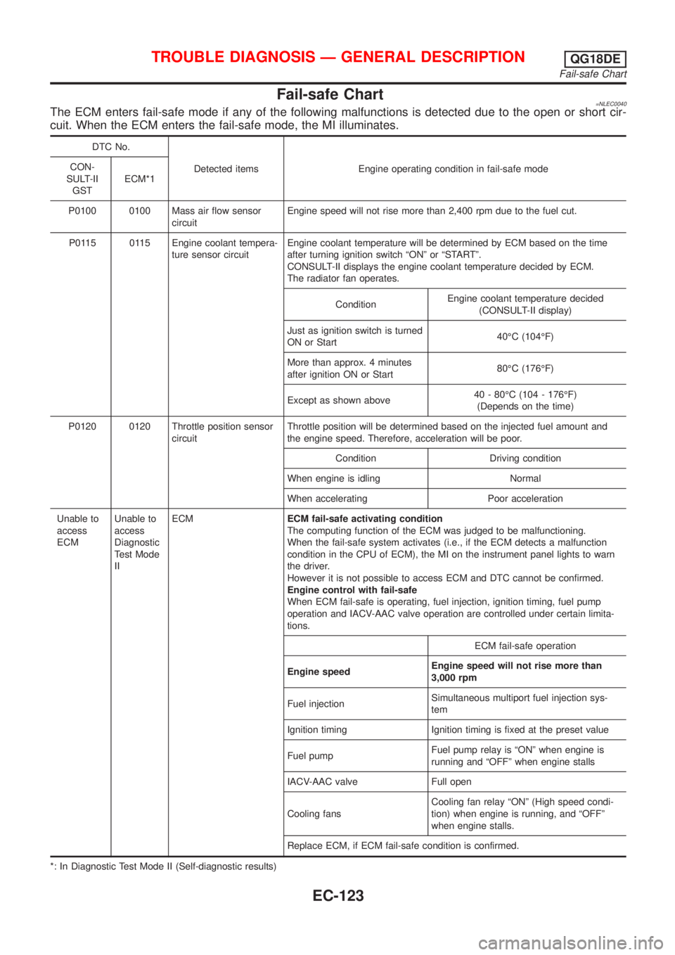
Fail-safe Chart=NLEC0040The ECM enters fail-safe mode if any of the following malfunctions is detected due to the open or short cir-
cuit. When the ECM enters the fail-safe mode, the MI illuminates.
DTC No.
Detected items Engine operating condition in fail-safe mode CON-
SULT-II
GSTECM*1
P0100 0100 Mass air flow sensor
circuitEngine speed will not rise more than 2,400 rpm due to the fuel cut.
P0115 0115 Engine coolant tempera-
ture sensor circuitEngine coolant temperature will be determined by ECM based on the time
after turning ignition switch ªONº or ªSTARTº.
CONSULT-II displays the engine coolant temperature decided by ECM.
The radiator fan operates.
ConditionEngine coolant temperature decided
(CONSULT-II display)
Just as ignition switch is turned
ON or Start40ÉC (104ÉF)
More than approx. 4 minutes
after ignition ON or Start80ÉC (176ÉF)
Except as shown above40 - 80ÉC (104 - 176ÉF)
(Depends on the time)
P0120 0120 Throttle position sensor
circuitThrottle position will be determined based on the injected fuel amount and
the engine speed. Therefore, acceleration will be poor.
Condition Driving condition
When engine is idling Normal
When accelerating Poor acceleration
Unable to
access
ECMUnable to
access
Diagnostic
Test Mode
IIECMECM fail-safe activating condition
The computing function of the ECM was judged to be malfunctioning.
When the fail-safe system activates (i.e., if the ECM detects a malfunction
condition in the CPU of ECM), the MI on the instrument panel lights to warn
the driver.
However it is not possible to access ECM and DTC cannot be confirmed.
Engine control with fail-safe
When ECM fail-safe is operating, fuel injection, ignition timing, fuel pump
operation and IACV-AAC valve operation are controlled under certain limita-
tions.
ECM fail-safe operation
Engine speedEngine speed will not rise more than
3,000 rpm
Fuel injectionSimultaneous multiport fuel injection sys-
tem
Ignition timing Ignition timing is fixed at the preset value
Fuel pumpFuel pump relay is ªONº when engine is
running and ªOFFº when engine stalls
IACV-AAC valve Full open
Cooling fansCooling fan relay ªONº (High speed condi-
tion) when engine is running, and ªOFFº
when engine stalls.
Replace ECM, if ECM fail-safe condition is confirmed.
*: In Diagnostic Test Mode II (Self-diagnostic results)
TROUBLE DIAGNOSIS Ð GENERAL DESCRIPTIONQG18DE
Fail-safe Chart
EC-123
Page 549 of 3051
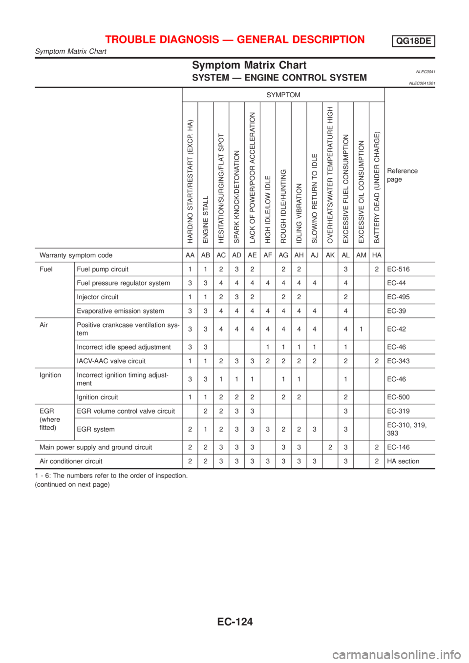
Symptom Matrix ChartNLEC0041SYSTEM Ð ENGINE CONTROL SYSTEMNLEC0041S01
SYMPTOM
Reference
page
HARD/NO START/RESTART (EXCP. HA)
ENGINE STALL
HESITATION/SURGING/FLAT SPOT
SPARK KNOCK/DETONATION
LACK OF POWER/POOR ACCELERATION
HIGH IDLE/LOW IDLE
ROUGH IDLE/HUNTING
IDLING VIBRATION
SLOW/NO RETURN TO IDLE
OVERHEATS/WATER TEMPERATURE HIGH
EXCESSIVE FUEL CONSUMPTION
EXCESSIVE OIL CONSUMPTION
BATTERY DEAD (UNDER CHARGE)
Warranty symptom code AA AB AC AD AE AF AG AH AJ AK AL AM HA
Fuel Fuel pump circuit11232 22 3 2EC-516
Fuel pressure regulator system334444444 4EC-44
Injector circuit11232 22 2EC-495
Evaporative emission system334444444 4EC-39
Air Positive crankcase ventilation sys-
tem334444444 41EC-42
Incorrect idle speed adjustment 3 31111 1EC-46
IACV-AAC valve circuit112332222 2 2EC-343
Ignition Incorrect ignition timing adjust-
ment33111 11 1EC-46
Ignition circuit11222 22 2EC-500
EGR
(where
fitted)EGR volume control valve circuit2233 3EC-319
EGR system212333223 3EC-310, 319,
393
Main power supply and ground circuit22333 33 23 2EC-146
Air conditioner circuit223333333 3 2HAsection
1 - 6: The numbers refer to the order of inspection.
(continued on next page)
TROUBLE DIAGNOSIS Ð GENERAL DESCRIPTIONQG18DE
Symptom Matrix Chart
EC-124
Page 550 of 3051
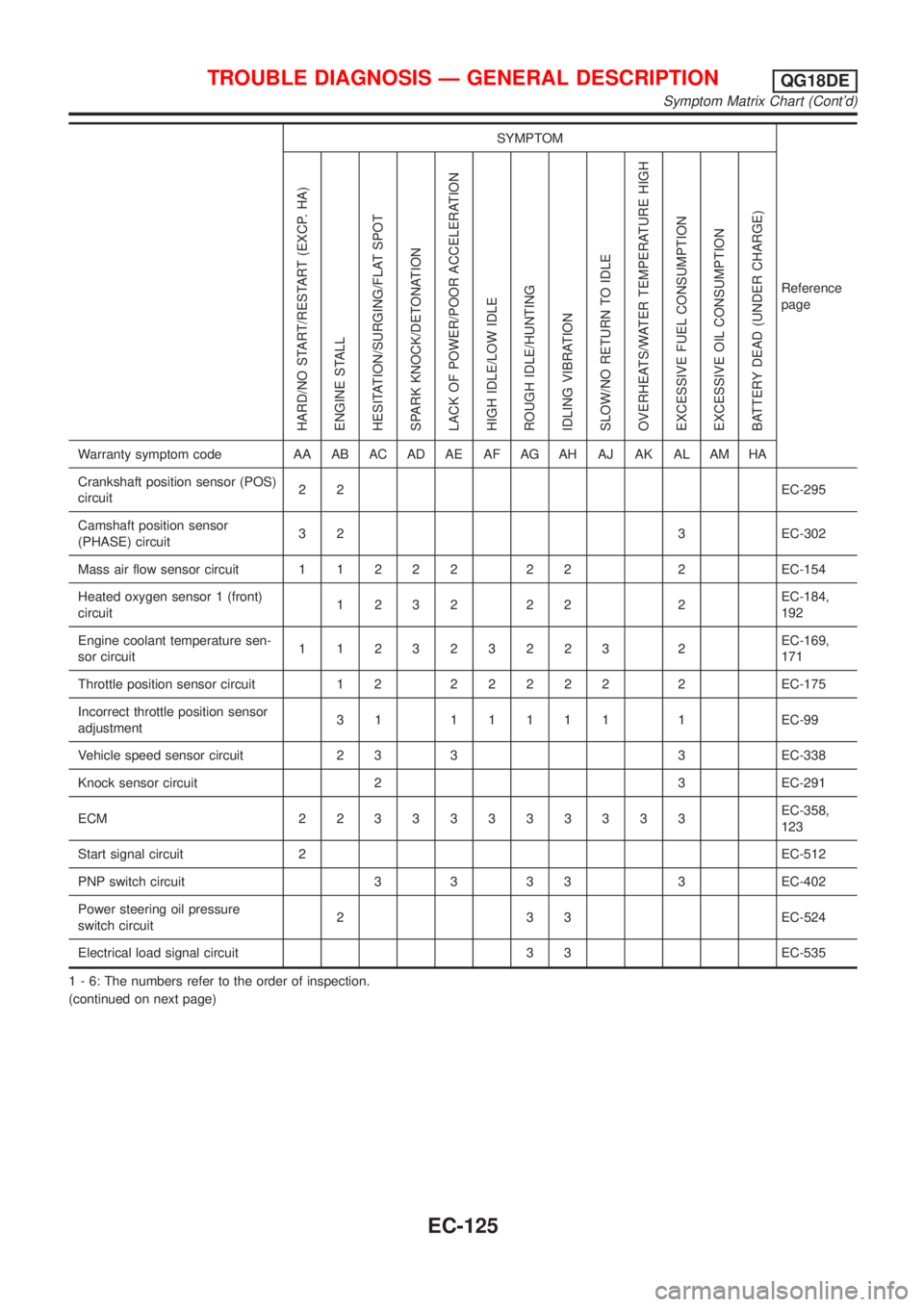
SYMPTOM
Reference
page
HARD/NO START/RESTART (EXCP. HA)
ENGINE STALL
HESITATION/SURGING/FLAT SPOT
SPARK KNOCK/DETONATION
LACK OF POWER/POOR ACCELERATION
HIGH IDLE/LOW IDLE
ROUGH IDLE/HUNTING
IDLING VIBRATION
SLOW/NO RETURN TO IDLE
OVERHEATS/WATER TEMPERATURE HIGH
EXCESSIVE FUEL CONSUMPTION
EXCESSIVE OIL CONSUMPTION
BATTERY DEAD (UNDER CHARGE)
Warranty symptom code AA AB AC AD AE AF AG AH AJ AK AL AM HA
Crankshaft position sensor (POS)
circuit22EC-295
Camshaft position sensor
(PHASE) circuit3 2 3 EC-302
Mass air flow sensor circuit11222 22 2EC-154
Heated oxygen sensor 1 (front)
circuit1232 22 2EC-184,
192
Engine coolant temperature sen-
sor circuit112323223 2EC-169,
171
Throttle position sensor circuit 1 222222 2EC-175
Incorrect throttle position sensor
adjustment31 11111 1EC-99
Vehicle speed sensor circuit 2 3 3 3 EC-338
Knock sensor circuit 2 3 EC-291
ECM 22333333333EC-358,
123
Start signal circuit 2EC-512
PNP switch circuit 3 3 3 3 3 EC-402
Power steering oil pressure
switch circuit2 3 3 EC-524
Electrical load signal circuit 3 3 EC-535
1 - 6: The numbers refer to the order of inspection.
(continued on next page)
TROUBLE DIAGNOSIS Ð GENERAL DESCRIPTIONQG18DE
Symptom Matrix Chart (Cont'd)
EC-125
Page 551 of 3051
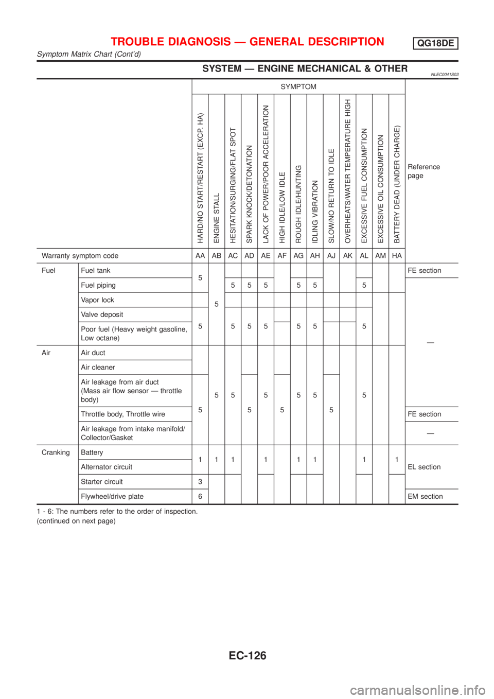
SYSTEM Ð ENGINE MECHANICAL & OTHERNLEC0041S03
SYMPTOM
Reference
page
HARD/NO START/RESTART (EXCP. HA)
ENGINE STALL
HESITATION/SURGING/FLAT SPOT
SPARK KNOCK/DETONATION
LACK OF POWER/POOR ACCELERATION
HIGH IDLE/LOW IDLE
ROUGH IDLE/HUNTING
IDLING VIBRATION
SLOW/NO RETURN TO IDLE
OVERHEATS/WATER TEMPERATURE HIGH
EXCESSIVE FUEL CONSUMPTION
EXCESSIVE OIL CONSUMPTION
BATTERY DEAD (UNDER CHARGE)
Warranty symptom code AA AB AC AD AE AF AG AH AJ AK AL AM HA
Fuel Fuel tank
5
5FE section
Fuel piping 5 5 5 5 5 5
Ð Vapor lock
Valve deposit
5 555 55 5
Poor fuel (Heavy weight gasoline,
Low octane)
Air Air duct
55555 5 Air cleaner
Air leakage from air duct
(Mass air flow sensor Ð throttle
body)
5555
Throttle body, Throttle wireFE section
Air leakage from intake manifold/
Collector/GasketÐ
Cranking Battery
111111 11
EL section Alternator circuit
Starter circuit 3
Flywheel/drive plate 6 EM section
1 - 6: The numbers refer to the order of inspection.
(continued on next page)
TROUBLE DIAGNOSIS Ð GENERAL DESCRIPTIONQG18DE
Symptom Matrix Chart (Cont'd)
EC-126