2001 NISSAN ALMERA TINO sport mode
[x] Cancel search: sport modePage 1194 of 3051

SEF662Y
Component InspectionNLEC1480HEATED OXYGEN SENSOR 2 (REAR)NLEC1480S01With CONSULT-II
1) Start engine and drive vehicle at a speed of more than 70 km/h
(43 MPH) for 2 consecutive minutes..
2) Stop vehicle with engine running.
3) Select ªFUEL INJECTIONº in ªACTIVE TESTº mode, and
select ªHO2S2 (B1)º as the monitor item with CONSULT-II.
4) Check ªHO2S2 (B1)º at idle speed when adjusting ªFUEL
INJECTIONº to±25%.
ªHO2S2 (B1)º should be above 0.68V at least once when
the ªFUEL INJECTIONº is +25%.
ªHO2S2 (B1)º should be below 0.45V at least once when
the ªFUEL INJECTIONº is þ25%.
CAUTION:
+Discard any heated oxygen sensor which has been
dropped from a height of more than 0.5 m (19.7 in) onto a
hard surface such as a concrete floor; use a new one.
+Before installing new oxygen sensor, clean exhaust sys-
tem threads using Oxygen Sensor Thread Cleaner tool
and approved anti-seize lubricant.
SEF244YC
SEF032X
Without CONSULT-II
1) Start engine and drive vehicle at a speed of 70 km/h (43 MPH)
for 2 consecutive minutes.
2) Stop vehicle with engine running.
3) Set voltmeter probes between ECM terminals 63 (HO2S2 sig-
nal) and engine ground.
4) Check the voltage when revving up to 4,000 rpm under no load
at least 10 times.
(Depress and release accelerator pedal as soon as possible.)
The voltage should be above 0.68V at least once.
If the voltage is above 0.68V at step 4, step 5 is not nec-
essary.
5) Keep vehicle at idling for 10 minutes, then check the voltage.
Or check the voltage when coasting from 80 km/h (50 MPH)
in D position with ªSPORTS MODE SWº OFF.
The voltage should be below 0.45V at least once.
CAUTION:
+Discard any heated oxygen sensor which has been
dropped from a height of more than 0.5 m (19.7 in) onto a
hard surface such as a concrete floor; use a new one.
+Before installing new oxygen sensor, clean exhaust sys-
tem threads using Oxygen Sensor Thread Cleaner tool
and approved anti-seize lubricant.
DTC P0138 HEATED OXYGEN SENSOR 2 (REAR) (MAX. VOLTAGE
MONITORING)
SR20DE
Component Inspection
EC-769
Page 1197 of 3051

10) Make sure that ªOKº is displayed after touching ªSELF-DIAG
RESULTSº.
If ªNGº is displayed, refer to ªDiagnostic Procedureº, EC-775.
SEF032X
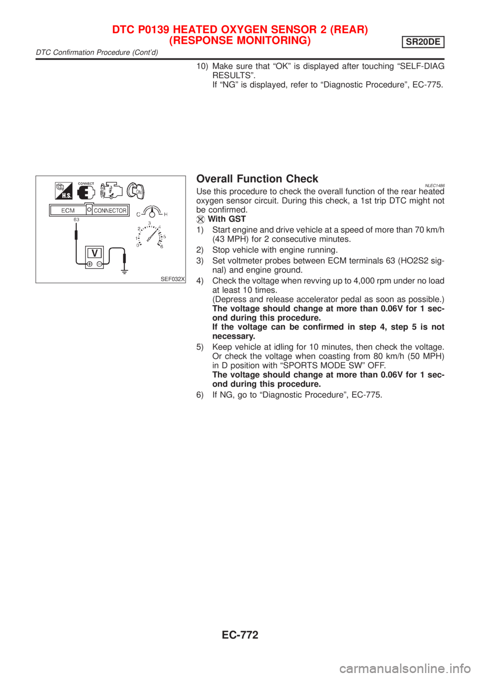
Overall Function CheckNLEC1486Use this procedure to check the overall function of the rear heated
oxygen sensor circuit. During this check, a 1st trip DTC might not
be confirmed.
With GST
1) Start engine and drive vehicle at a speed of more than 70 km/h
(43 MPH) for 2 consecutive minutes.
2) Stop vehicle with engine running.
3) Set voltmeter probes between ECM terminals 63 (HO2S2 sig-
nal) and engine ground.
4) Check the voltage when revving up to 4,000 rpm under no load
at least 10 times.
(Depress and release accelerator pedal as soon as possible.)
The voltage should change at more than 0.06V for 1 sec-
ond during this procedure.
If the voltage can be confirmed in step 4, step 5 is not
necessary.
5) Keep vehicle at idling for 10 minutes, then check the voltage.
Or check the voltage when coasting from 80 km/h (50 MPH)
in D position with ªSPORTS MODE SWº OFF.
The voltage should change at more than 0.06V for 1 sec-
ond during this procedure.
6) If NG, go to ªDiagnostic Procedureº, EC-775.
DTC P0139 HEATED OXYGEN SENSOR 2 (REAR)
(RESPONSE MONITORING)
SR20DE
DTC Confirmation Procedure (Cont'd)
EC-772
Page 1203 of 3051

SEF662Y
Component InspectionNLEC1489HEATED OXYGEN SENSOR 2 (REAR)NLEC1489S01With CONSULT-II
1) Start engine and drive vehicle at a speed of more than 70 km/h
(43 MPH) for 2 consecutive minutes.
2) Stop vehicle with engine running.
3) Select ªFUEL INJECTIONº in ªACTIVE TESTº mode, and
select ªHO2S2 (B1)º as the monitor item with CONSULT-II.
4) Check ªHO2S2 (B1)º at idle speed when adjusting ªFUEL
INJECTIONº to±25%.
ªHO2S2 (B1)º should be above 0.68V at least once when
the ªFUEL INJECTIONº is +25%.
ªHO2S2 (B1)º should be below 0.45V at least once when
the ªFUEL INJECTIONº is þ25%.
CAUTION:
+Discard any heated oxygen sensor which has been
dropped from a height of more than 0.5 m (19.7 in) onto a
hard surface such as a concrete floor; use a new one.
+Before installing new oxygen sensor, clean exhaust sys-
tem threads using Oxygen Sensor Thread Cleaner tool
and approved anti-seize lubricant.
SEF244YC
SEF032X
Without CONSULT-II
1) Start engine and drive vehicle at a speed of more than 70 km/h
(43 MPH) for 2 consecutive minutes.
2) Stop vehicle with engine running.
3) Set voltmeter probes between ECM terminals 63 (HO2S2 sig-
nal) and engine ground.
4) Check the voltage when revving up to 4,000 rpm under no load
at least 10 times.
(Depress and release accelerator pedal as soon as possible.)
The voltage should be above 0.68V at least once.
If the voltage is above 0.68V at step 4, step 5 is not nec-
essary.
5) Keep vehicle at idling for 10 minutes, then check the voltage.
Or check the voltage when coasting from 80 km/h (50 MPH)
in D position with ªSPORTS MODE SWº OFF.
The voltage should be below 0.45V at least once.
CAUTION:
+Discard any heated oxygen sensor which has been
dropped from a height of more than 0.5 m (19.7 in) onto a
hard surface such as a concrete floor; use a new one.
+Before installing new oxygen sensor, clean exhaust sys-
tem threads using Oxygen Sensor Thread Cleaner tool
and approved anti-seize lubricant.
DTC P0139 HEATED OXYGEN SENSOR 2 (REAR)
(RESPONSE MONITORING)
SR20DE
Component Inspection
EC-778
Page 1210 of 3051

SEF244YC
SEF032X
Without CONSULT-II
1) Start engine and drive vehicle at a speed of more than 70 km/h
(43 MPH) for 2 consecutive minutes.
2) Stop vehicle with engine running.
3) Set voltmeter probes between ECM terminals 63 (HO2S2 sig-
nal) and engine ground.
4) Check the voltage when revving up to 4,000 rpm under no load
at least 10 times.
(Depress and release accelerator pedal as soon as possible.)
The voltage should be above 0.68V at least once.
If the voltage is above 0.68V at step 4, step 5 is not nec-
essary.
5) Keep vehicle at idling for 10 minutes, then check the voltage.
Or check the voltage when coasting from 80 km/h (50 MPH)
in D position with ªSPORTS MODE SWº OFF.
The voltage should be below 0.45V at least once.
CAUTION:
+Discard any heated oxygen sensor which has been
dropped from a height of more than 0.5 m (19.7 in) onto a
hard surface such as a concrete floor; use a new one.
+Before installing new oxygen sensor, clean exhaust sys-
tem threads using Oxygen Sensor Thread Cleaner tool
and approved anti-seize lubricant.
DTC P0140 HEATED OXYGEN SENSOR 2 (REAR)
(HIGH VOLTAGE)
SR20DE
Component Inspection (Cont'd)
EC-785
Page 1384 of 3051

Diagnostic ProcedureNLEC1801
1 CHECK OVERALL FUNCTION-I
1. Start engine and drive the vehicle at over 70 km/h (43 MPH) for 2 consecutive minutes.
2. Stop vehicle and keep the engine running.
3. Set voltmeter probes between ECM terminals 63 [HO2S2 (B1) signal] and ground.
4. Check the voltage while revving up to 4,000 rpm under no load at least 10 times.
(Depress and release the accelerator pedal as quickly as possible.)
SEF240Z
OK or NG
OK©INSPECTION END
NG©GO TO 2.
2 CHECK OVERALL FUNCTION-II
Keep engine at idle for 10 minutes, then check the voltage between ECM terminal 63 and ground, or check the voltage
when coasting at 80 km/h (50 MPH) in ªDº position with ªSPORTS MODE SWº OFF.
SEF240Z
OK or NG
OK©INSPECTION END
NG©GO TO 3.
HEATED OXYGEN SENSOR 2 (REAR)SR20DE
Diagnostic Procedure
EC-959
Page 1387 of 3051

SEF032X
Without CONSULT-II
1) Start engine and drive vehicle at a speed of more than 70 km/h
(43 MPH) for 2 consecutive minutes.
2) Stop vehicle with engine running.
3) Set voltmeter probes between ECM terminals 63 (HO2S2 sig-
nal) and engine ground.
4) Check the voltage when revving up to 4,000 rpm under no load
at least 10 times.
(Depress and release accelerator pedal as soon as possible.)
The voltage should be above 0.68V at least once.
If the voltage is above 0.68V at step 4, step 5 is not nec-
essary.
5) Keep vehicle at idling for 10 minutes, then check the voltage.
Or check the voltage when coasting from 80 km/h (50 MPH)
in D position with ªSPORTS MODE SWº OFF.
The voltage should be below 0.45V at least once.
CAUTION:
+Discard any heated oxygen sensor which has been
dropped from a height of more than 0.5 m (19.7 in) onto a
hard surface such as a concrete floor; use a new one.
+Before installing new oxygen sensor, clean exhaust sys-
tem threads using Oxygen Sensor Thread Cleaner tool
and approved anti-seize lubricant.
HEATED OXYGEN SENSOR 2 (REAR)SR20DE
Component Inspection (Cont'd)
EC-962
Page 2132 of 3051

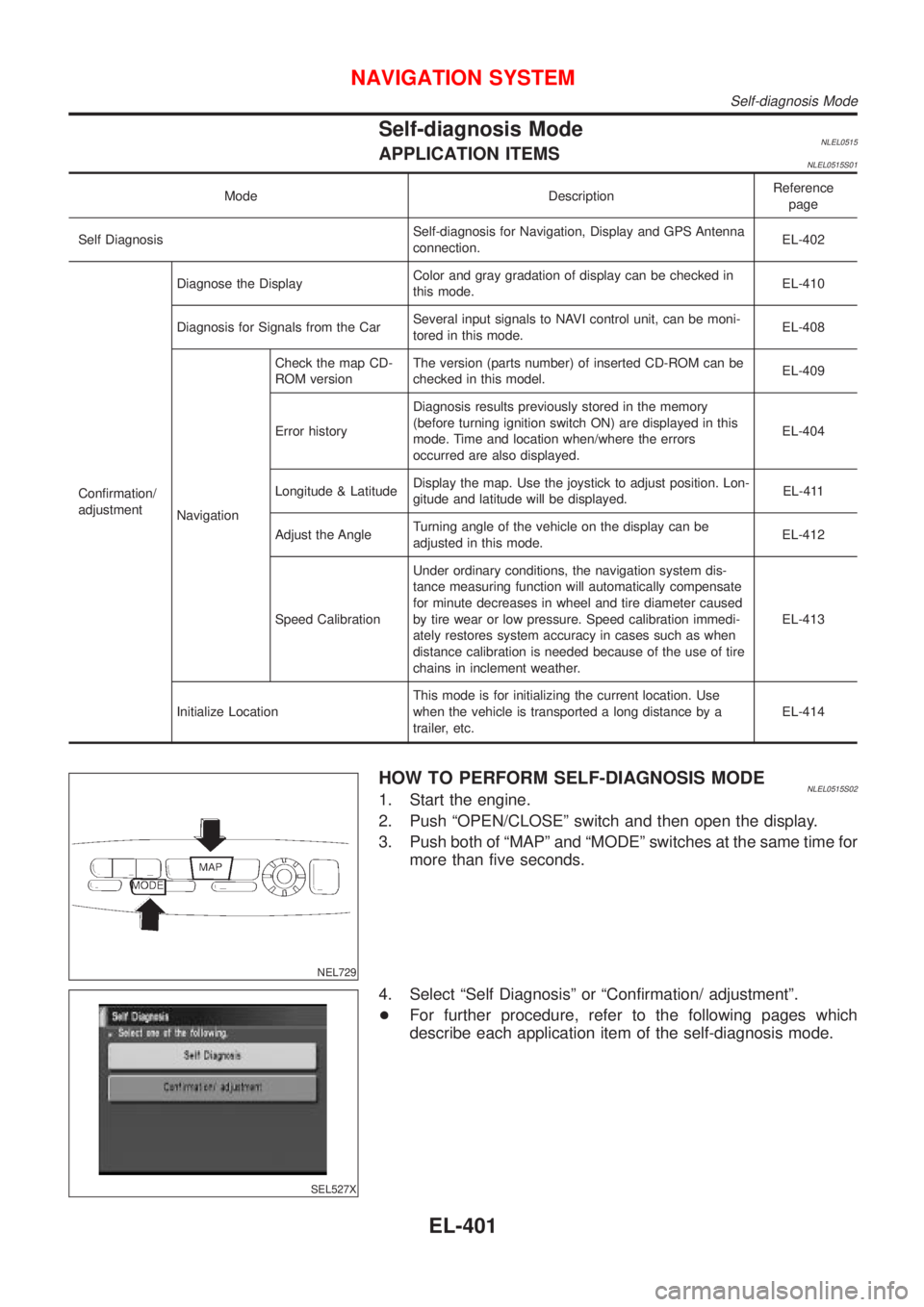
Self-diagnosis ModeNLEL0515APPLICATION ITEMSNLEL0515S01
Mode DescriptionReference
page
Self DiagnosisSelf-diagnosis for Navigation, Display and GPS Antenna
connection.EL-402
Confirmation/
adjustmentDiagnose the DisplayColor and gray gradation of display can be checked in
this mode.EL-410
Diagnosis for Signals from the CarSeveral input signals to NAVI control unit, can be moni-
tored in this mode.EL-408
NavigationCheck the map CD-
ROM versionThe version (parts number) of inserted CD-ROM can be
checked in this model.EL-409
Error historyDiagnosis results previously stored in the memory
(before turning ignition switch ON) are displayed in this
mode. Time and location when/where the errors
occurred are also displayed.EL-404
Longitude & LatitudeDisplay the map. Use the joystick to adjust position. Lon-
gitude and latitude will be displayed.EL-411
Adjust the AngleTurning angle of the vehicle on the display can be
adjusted in this mode.EL-412
Speed CalibrationUnder ordinary conditions, the navigation system dis-
tance measuring function will automatically compensate
for minute decreases in wheel and tire diameter caused
by tire wear or low pressure. Speed calibration immedi-
ately restores system accuracy in cases such as when
distance calibration is needed because of the use of tire
chains in inclement weather.EL-413
Initialize LocationThis mode is for initializing the current location. Use
when the vehicle is transported a long distance by a
trailer, etc.EL-414
NEL729
HOW TO PERFORM SELF-DIAGNOSIS MODENLEL0515S021. Start the engine.
2. Push ªOPEN/CLOSEº switch and then open the display.
3. Push both of ªMAPº and ªMODEº switches at the same time for
more than five seconds.
SEL527X
4. Select ªSelf Diagnosisº or ªConfirmation/ adjustmentº.
+For further procedure, refer to the following pages which
describe each application item of the self-diagnosis mode.
NAVIGATION SYSTEM
Self-diagnosis Mode
EL-401
Page 2145 of 3051

ªINITIALIZE LOCATIONº MODE=NLEL0516S09This procedure is for initializing the current location. Perform ªIni-
tialize Locationº when the vehicle has been transported a long dis-
tance by trailer, etc.
Map with grey background appears and the vehicle location can-
not be adjusted by scrolling the display when the vehicle location
in the memory is out of the area of the inserted map data.
Perform ªInitialize Locationº when this occurs.
NOTE:
+Only initialize the system when the NAVI control unit is
replaced. If the system is initialized in other cases, it may
cause inaccurate positioning of the position marker for a
while.
+Initialize the system outside for receiving the radio wave
from the GPS satellite.
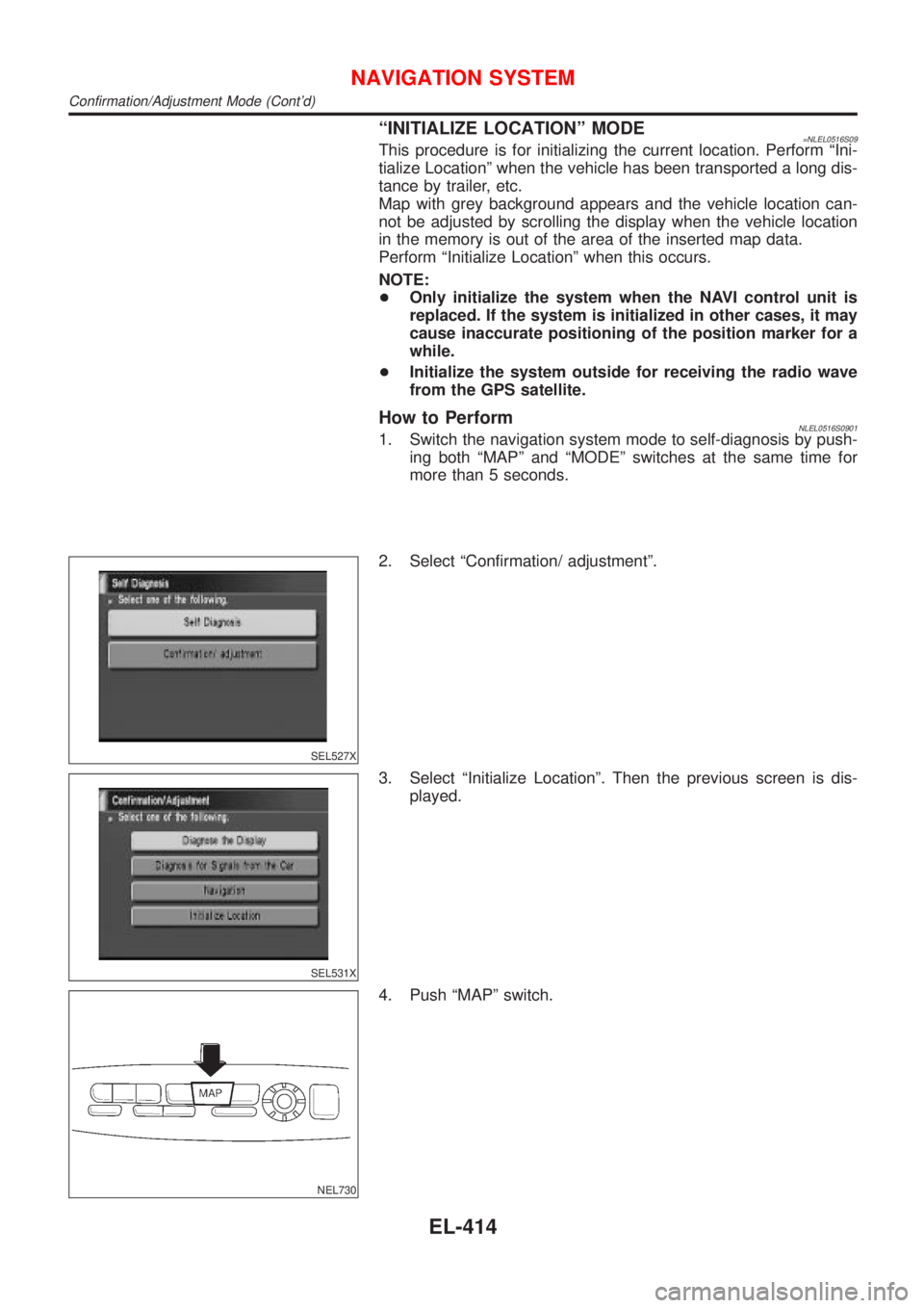
How to PerformNLEL0516S09011. Switch the navigation system mode to self-diagnosis by push-
ing both ªMAPº and ªMODEº switches at the same time for
more than 5 seconds.
SEL527X
2. Select ªConfirmation/ adjustmentº.
SEL531X
3. Select ªInitialize Locationº. Then the previous screen is dis-
played.
NEL730
4. Push ªMAPº switch.
NAVIGATION SYSTEM
Confirmation/Adjustment Mode (Cont'd)
EL-414