Page 33 of 3051

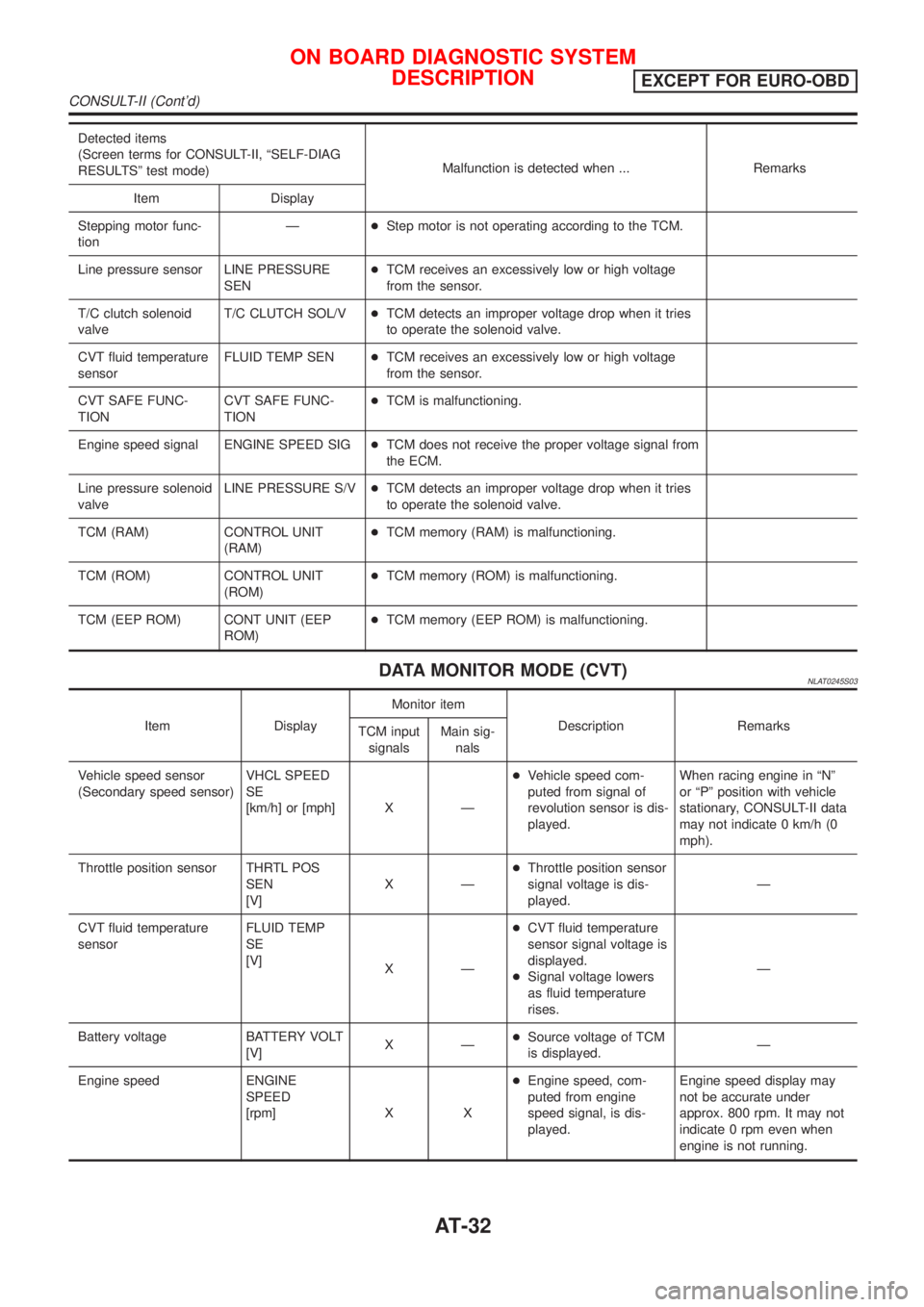
Detected items
(Screen terms for CONSULT-II, ªSELF-DIAG
RESULTSº test mode)Malfunction is detected when ... Remarks
Item Display
Stepping motor func-
tionÐ+Step motor is not operating according to the TCM.
Line pressure sensor LINE PRESSURE
SEN+TCM receives an excessively low or high voltage
from the sensor.
T/C clutch solenoid
valveT/C CLUTCH SOL/V+TCM detects an improper voltage drop when it tries
to operate the solenoid valve.
CVT fluid temperature
sensorFLUID TEMP SEN+TCM receives an excessively low or high voltage
from the sensor.
CVT SAFE FUNC-
TIONCVT SAFE FUNC-
TION+TCM is malfunctioning.
Engine speed signal ENGINE SPEED SIG+TCM does not receive the proper voltage signal from
the ECM.
Line pressure solenoid
valveLINE PRESSURE S/V+TCM detects an improper voltage drop when it tries
to operate the solenoid valve.
TCM (RAM) CONTROL UNIT
(RAM)+TCM memory (RAM) is malfunctioning.
TCM (ROM) CONTROL UNIT
(ROM)+TCM memory (ROM) is malfunctioning.
TCM (EEP ROM) CONT UNIT (EEP
ROM)+TCM memory (EEP ROM) is malfunctioning.
DATA MONITOR MODE (CVT)NLAT0245S03
Item DisplayMonitor item
Description Remarks
TCM input
signalsMain sig-
nals
Vehicle speed sensor
(Secondary speed sensor)VHCL SPEED
SE
[km/h] or [mph] X Ð+Vehicle speed com-
puted from signal of
revolution sensor is dis-
played.When racing engine in ªNº
or ªPº position with vehicle
stationary, CONSULT-II data
may not indicate 0 km/h (0
mph).
Throttle position sensor THRTL POS
SEN
[V]XÐ+Throttle position sensor
signal voltage is dis-
played.Ð
CVT fluid temperature
sensorFLUID TEMP
SE
[V]
XÐ+CVT fluid temperature
sensor signal voltage is
displayed.
+Signal voltage lowers
as fluid temperature
rises.Ð
Battery voltage BATTERY VOLT
[V]XÐ+Source voltage of TCM
is displayed.Ð
Engine speed ENGINE
SPEED
[rpm] X X+Engine speed, com-
puted from engine
speed signal, is dis-
played.Engine speed display may
not be accurate under
approx. 800 rpm. It may not
indicate 0 rpm even when
engine is not running.
ON BOARD DIAGNOSTIC SYSTEM
DESCRIPTION
EXCEPT FOR EURO-OBD
CONSULT-II (Cont'd)
AT-32
Page 43 of 3051
DIAGNOSTIC WORKSHEET=NLAT0023S01Information from CustomerNLAT0023S0101KEY POINTS
WHAT..... Vehicle & CVT model
WHEN..... Date, Frequencies
WHERE..... Road conditions
HOW..... Operating conditions, Symptoms
Customer name MR/MS Model & Year VIN
Trans. model Engine Mileage
Incident Date Manuf. Date In Service Date
FrequencyNContinuousNIntermittent ( times a day)
NVehicle does not move. (NAny positionNParticular position)
SymptomsNLockup malfunction
NShift point too high or too low.
NShift shock or slip (NN®DNLockupNAny drive position)
NNoise or vibration
NNo pattern select
NOthers
()
SPORT indicator lamp Blinks for about 8 seconds.
NContinuously litNNot lit
Malfunction indicator (MI)NContinuously litNNot lit
TROUBLE DIAGNOSIS Ð INTRODUCTIONEURO-OBD
Introduction (Cont'd)
AT-42
Page 48 of 3051
DIAGNOSTIC WORKSHEET=NLAT0247S01Information from CustomerNLAT0247S0101KEY POINTS
WHAT..... Vehicle & CVT model
WHEN..... Date, Frequencies
WHERE..... Road conditions
HOW..... Operating conditions, Symptoms
Customer name MR/MS Model & Year VIN
Trans. model Engine Mileage
Incident Date Manuf. Date In Service Date
FrequencyNContinuousNIntermittent ( times a day)
NVehicle does not move. (NAny positionNParticular position)
SymptomsNLockup malfunction
NShift point too high or too low.
NShift shock or slip (NN®DNLockupNAny drive position)
NNoise or vibration
NNo pattern select
NOthers
()
SPORT indicator lamp Blinks for about 8 seconds.
NContinuously litNNot lit
TROUBLE DIAGNOSIS Ð
INTRODUCTION
EXCEPT FOR EURO-OBD
Introduction (Cont'd)
AT-47
Page 60 of 3051

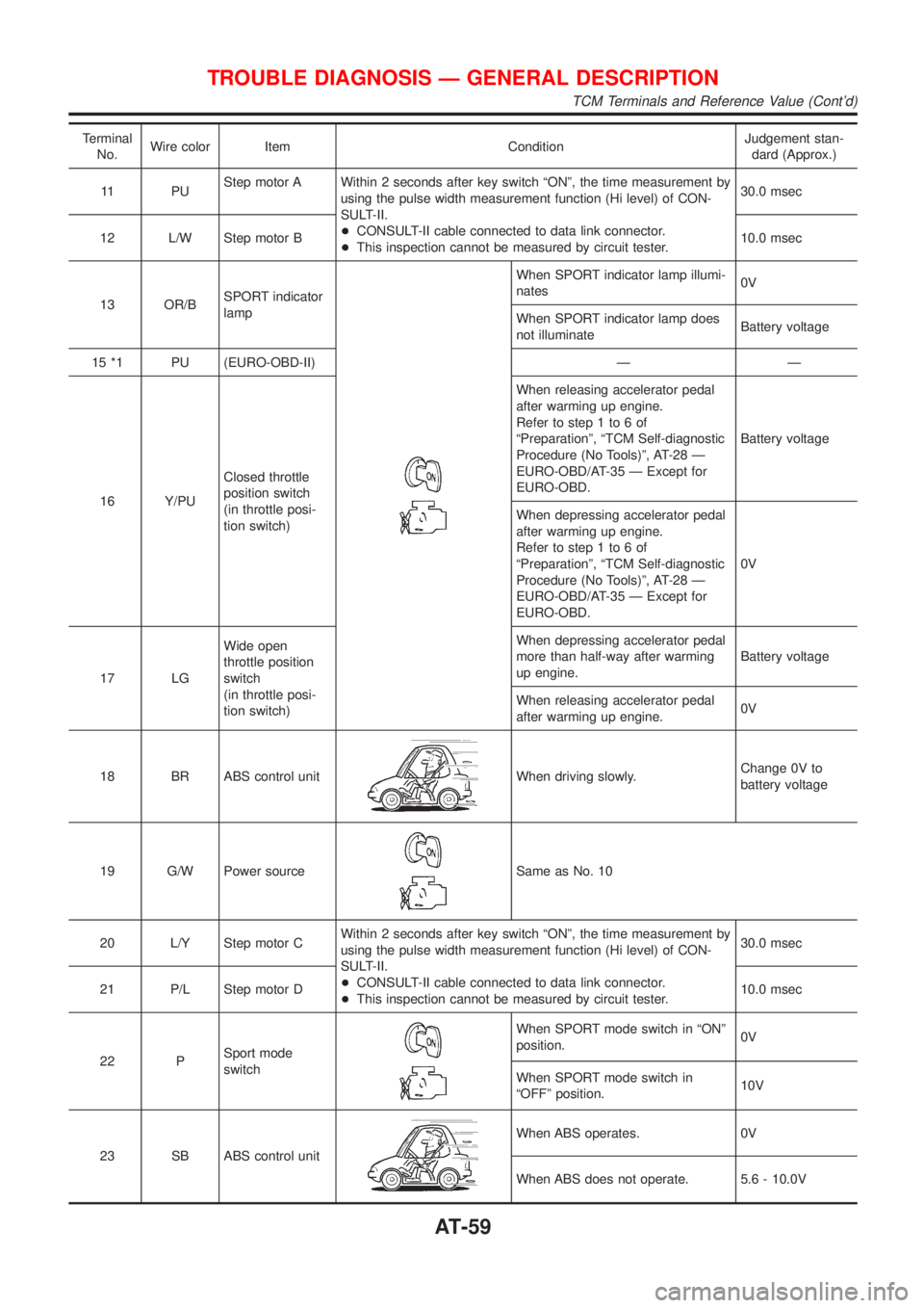
Terminal
No.Wire color Item ConditionJudgement stan-
dard (Approx.)
11 P UStep motor A Within 2 seconds after key switch ªONº, the time measurement by
using the pulse width measurement function (Hi level) of CON-
SULT-II.
+CONSULT-II cable connected to data link connector.
+This inspection cannot be measured by circuit tester.30.0 msec
12 L/W Step motor B10.0 msec
13 OR/BSPORT indicator
lamp
When SPORT indicator lamp illumi-
nates0V
When SPORT indicator lamp does
not illuminateBattery voltage
15 *1 PU (EURO-OBD-II) Ð Ð
16 Y/PUClosed throttle
position switch
(in throttle posi-
tion switch)When releasing accelerator pedal
after warming up engine.
Refer to step 1 to 6 of
ªPreparationº, ªTCM Self-diagnostic
Procedure (No Tools)º, AT-28 Ð
EURO-OBD/AT-35 Ð Except for
EURO-OBD.Battery voltage
When depressing accelerator pedal
after warming up engine.
Refer to step 1 to 6 of
ªPreparationº, ªTCM Self-diagnostic
Procedure (No Tools)º, AT-28 Ð
EURO-OBD/AT-35 Ð Except for
EURO-OBD.0V
17 LGWide open
throttle position
switch
(in throttle posi-
tion switch)When depressing accelerator pedal
more than half-way after warming
up engine.Battery voltage
When releasing accelerator pedal
after warming up engine.0V
18 BR ABS control unit
When driving slowly.Change 0V to
battery voltage
19 G/W Power source
Same as No. 10
20 L/Y Step motor CWithin 2 seconds after key switch ªONº, the time measurement by
using the pulse width measurement function (Hi level) of CON-
SULT-II.
+CONSULT-II cable connected to data link connector.
+This inspection cannot be measured by circuit tester.30.0 msec
21 P/L Step motor D10.0 msec
22 PSport mode
switch
When SPORT mode switch in ªONº
position.0V
When SPORT mode switch in
ªOFFº position.10V
23 SB ABS control unit
When ABS operates. 0V
When ABS does not operate. 5.6 - 10.0V
TROUBLE DIAGNOSIS Ð GENERAL DESCRIPTION
TCM Terminals and Reference Value (Cont'd)
AT-59
Page 68 of 3051

SAT250K
SAT255K
DIAGNOSTIC TROUBLE CODE (DTC) CONFIRMATION
PROCEDURE
NLAT0032S03CAUTION:
Always drive vehicle at a safe speed.
NOTE:
If ªDIAGNOSTIC TROUBLE CODE CONFIRMATION PROCE-
DUREº has been previously conducted, always turn ignition
switch ªOFFº and wait at least 5 seconds before conducting
the next test.
After the repair, perform the following procedure to confirm the
malfunction is eliminated.
With CONSULT-II
1) Turn ignition switch ªONº and select ªDATA MONITORº mode
for ªCVTº with CONSULT-II.
2) Make sure that output voltage of CVT fluid temperature sen-
sor is within the range below.
FLUID TEMP SEN: 0.5 - 1.5V
If out of range, drive the vehicle to decrease the voltage
(warm up the fluid) or stop engine to increase the voltage
(cool down the fluid)
3) Select ªDATA MONITORº mode for ªENGINEº with CONSULT-
II.
4) Start engine and maintain the following conditions for at least
15 consecutive seconds.
VHCL SPEED SE: 10 km/h (6 MPH) or more
THRTL POS SEN: More than 1.0/8
Selector lever: D position
ENG SPEED: 450 rpm or more
If the check result is ªNGº, go to ªDiagnostic Procedureº, AT-70.
With GST
Follow the procedure ªWith CONSULT-IIº.
DTC P0705 PARK/NEUTRAL POSITION (PNP) SWITCHEURO-OBD
Description (Cont'd)
AT-67
Page 75 of 3051
SAT250K
SAT255K
DIAGNOSTIC TROUBLE CODE (DTC) CONFIRMATION
PROCEDURE
NLAT0035S04CAUTION:
Always drive vehicle at a safe speed.
NOTE:
If ªDIAGNOSTIC TROUBLE CODE CONFIRMATION PROCE-
DUREº has been previously conducted, always turn ignition
switch ªOFFº and wait at least 5 seconds before conducting
the next test.
After the repair, perform the following procedure to confirm the
malfunction is eliminated.
With CONSULT-II
1) Turn ignition switch ªONº and select ªDATA MONITORº mode
for ªENGINEº with CONSULT-II.
2) Start engine and maintain the following conditions for at least
10 minutes (Total). (It is not necessary to maintain continu-
ously.)
CMPS´RPM (REF): 450 rpm or more
VHCL SPEED SE: 10 km/h (6 MPH) or more
THRTL POS SEN: More than 1.3V
Selector lever: D position
If the check result is NG, go to ªDiagnostic Procedureº, AT-77.
With GST
Follow the procedure ªWith CONSULT-IIº.
DTC P0710 CVT FLUID TEMPERATURE
SENSOR CIRCUIT
EURO-OBD
Description (Cont'd)
AT-74
Page 80 of 3051

DescriptionNLAT0220The primary speed sensor detects the primary pulley revolution
speed sends a signal to the ECM.
TCM TERMINALS AND REFERENCE VALUENLAT0220S01Remarks: Specification data are reference values.
Terminal
No.Wire color Item ConditionJudgement stan-
dard (Approx.)
38 G/YPrimary speed
sensorWhen driving [L position, 20 km/h (12 MPH)], the pulse measure-
ment by using the pulse measurement function of CONSULT-II.
+CONSULT-II cable connected to data link connector.
+This inspection cannot be measured by circuit tester.900 Hz
ON BOARD DIAGNOSIS LOGICNLAT0220S02
Diagnostic trouble code Malfunction is detected when ... Check items (Possible cause)
: PRI SPEED SIG/CIRC
TCM does not receive the proper voltage
signal from the sensor.+Harness or connectors
(The sensor circuit is open or shorted.)
+Primary speed sensor
: P0715
: MIL Code No. 0715
SAT250K
SAT252K
SAT255K
DIAGNOSTIC TROUBLE CODE (DTC) CONFIRMATION
PROCEDURE
NLAT0220S03CAUTION:
+Always drive vehicle at a safe speed.
+Be careful not to rev engine into the red zone on the
tachometer.
NOTE:
If ªDIAGNOSTIC TROUBLE CODE CONFIRMATION PROCE-
DUREº has been previously conducted, always turn ignition
switch ªOFFº and wait at least 5 seconds before conducting
the next test.
After the repair, perform the following procedure to confirm the
malfunction is eliminated.
With CONSULT-II
1) Turn ignition switch ªONº and select ªDATA MONITORº mode
for ªENGINEº with CONSULT-II.
2) Start engine and maintain the following conditions for at least
5 consecutive seconds.
VHCL SPEED SE: 10 km/h (6 MPH) or more
THRTL POS SEN: More than 1.3V
Selector lever: D position
ENG SPEED: 450 rpm or more
Driving location: Driving the vehicle uphill (increased
engine load) will help maintain the driving conditions
required for this test.
If the check result is NG, go to ªDiagnostic Procedureº, AT-82.
With GST
Follow the procedure ªWith CONSULT-IIº.
DTC P0715 PRIMARY SPEED SENSOREURO-OBD
Description
AT-79
Page 86 of 3051
SAT252K
SAT255K
With CONSULT-II
1) Turn ignition switch ªONº and select ªDATA MONITORº mode
for ªENGINEº with CONSULT-II.
2) Start engine and maintain the following conditions for at least
12 consecutive seconds.
THRTL POS SEN: More than 1.3V
Selector lever: D position
Driving location: Driving the vehicle uphill (increased
engine load) will help maintain the driving conditions
required for this test.
If the check result is NG, go to ªDIAGNOSTIC PROCEDUREº,
AT-88.
With GST
Follow the procedure ªWith CONSULT-IIº.
DTC P0720 VEHICLE SPEED SENSOR
(SECONDARY SPEED SENSOR)
EURO-OBD
Description (Cont'd)
AT-85