2001 NISSAN ALMERA check engine light
[x] Cancel search: check engine lightPage 1352 of 2898
+Erasing the emission-related diagnostic information using CONSULT-II is easier and quicker than
switching the diagnostic test mode using the data link connector.
Malfunction Indicator (MI)
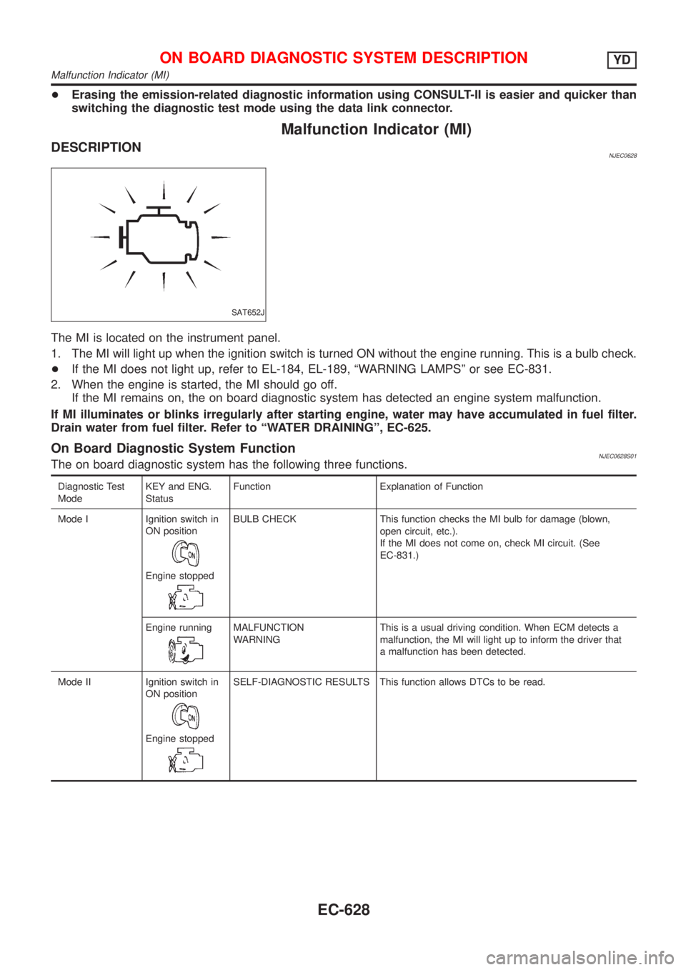
DESCRIPTIONNJEC0628
SAT652J
The MI is located on the instrument panel.
1. The MI will light up when the ignition switch is turned ON without the engine running. This is a bulb check.
+If the MI does not light up, refer to EL-184, EL-189, ªWARNING LAMPSº or see EC-831.
2. When the engine is started, the MI should go off.
If the MI remains on, the on board diagnostic system has detected an engine system malfunction.
If MI illuminates or blinks irregularly after starting engine, water may have accumulated in fuel filter.
Drain water from fuel filter. Refer to ªWATER DRAININGº, EC-625.
On Board Diagnostic System FunctionNJEC0628S01The on board diagnostic system has the following three functions.
Diagnostic Test
ModeKEY and ENG.
StatusFunction Explanation of Function
Mode I Ignition switch in
ON position
Engine stopped
BULB CHECK This function checks the MI bulb for damage (blown,
open circuit, etc.).
If the MI does not come on, check MI circuit. (See
EC-831.)
Engine running
MALFUNCTION
WARNINGThis is a usual driving condition. When ECM detects a
malfunction, the MI will light up to inform the driver that
a malfunction has been detected.
Mode II Ignition switch in
ON position
Engine stopped
SELF-DIAGNOSTIC RESULTS This function allows DTCs to be read.
ON BOARD DIAGNOSTIC SYSTEM DESCRIPTIONYD
Malfunction Indicator (MI)
EC-628
Page 1365 of 2898
Basic InspectionNJEC0632Precaution:
Perform Basic Inspection without electrical or mechanical
loads applied;
+Headlamp switch is OFF,
+On vehicles equipped with daytime light systems, set
lighting switch to the 1st position to light only small
lamps.
+Air conditioner switch is OFF,
+Rear defogger switch is OFF,
+Steering wheel is in the straight-ahead position, etc.
1 INSPECTION START
1. Check service records for any recent repairs that may indicate a related problem.
2. Check the current need for scheduled maintenance, especially for fuel filter and air cleaner filter. Refer to MA-6, ªPeri-
odic Maintenanceº.
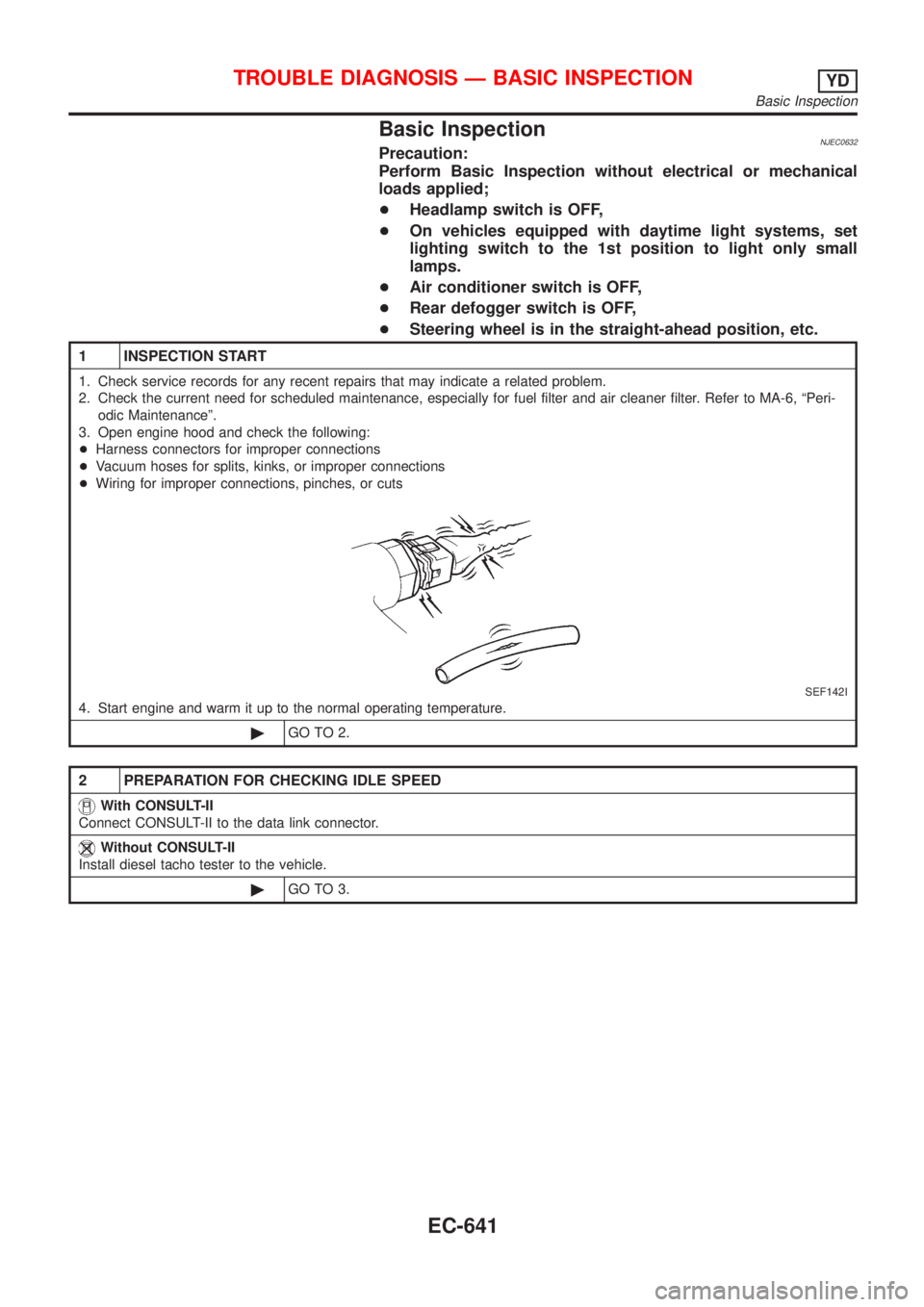
3. Open engine hood and check the following:
+Harness connectors for improper connections
+Vacuum hoses for splits, kinks, or improper connections
+Wiring for improper connections, pinches, or cuts
SEF142I
4. Start engine and warm it up to the normal operating temperature.
©GO TO 2.
2 PREPARATION FOR CHECKING IDLE SPEED
With CONSULT-II
Connect CONSULT-II to the data link connector.
Without CONSULT-II
Install diesel tacho tester to the vehicle.
©GO TO 3.
TROUBLE DIAGNOSIS Ð BASIC INSPECTIONYD
Basic Inspection
EC-641
Page 1559 of 2898
ELECTRICAL SYSTEM
SECTION
EL
CONTENTS
PRECAUTIONS...............................................................5
Supplemental Restraint System (SRS)²AIR
BAG²and²SEAT BELT PRE-TENSIONER²...............5
Wiring Diagrams and Trouble Diagnosis .....................5
HARNESS CONNECTOR................................................6
Description ...................................................................6
STANDARDIZED RELAY................................................8
Description ...................................................................8
POWER SUPPLY ROUTING.........................................10
Schematic/Sedan .......................................................10
Wiring Diagram - POWER -/Sedan With
Gasoline Engine ........................................................ 11
Wiring Diagram - POWER -/Sedan With Diesel
Engine ........................................................................19
Schematic/Hatchback ................................................26
Wiring Diagram - POWER -/Hatchback ....................28
Inspection...................................................................38
GROUND........................................................................39
Ground Distribution ....................................................39
COMBINATION SWITCH..............................................56
Check/Sedan .............................................................56
Check/Hatchback .......................................................57
Replacement ..............................................................58
STEERING SWITCH......................................................59
Check .........................................................................59
HEADLAMP...................................................................60
Wiring Diagram - H/LAMP -/Hatchback.....................60
Wiring Diagram - H/LAMP -/Sedan ...........................61
Trouble Diagnoses.....................................................63
Bulb Replacement .....................................................64
Aiming Adjustment .....................................................65
HEADLAMP - DAYTIME LIGHT SYSTEM -.................67
System Description ....................................................67
Schematic/Sedan .......................................................68
Wiring Diagram - DTRL -/Sedan ...............................69
Schematic/Hatchback ................................................72
Wiring Diagram - DTRL -/Hatchback .........................73
Trouble Diagnoses.....................................................76
Bulb Replacement .....................................................76Aiming Adjustment .....................................................77
HEADLAMP - HEADLAMP AIMING CONTROL -........78
Wiring Diagram - H/AIM -/Sedan...............................78
Wiring Diagram - H/AIM -/Hatchback ........................79
PARKING, LICENSE AND TAIL LAMPS.....................81
Wiring Diagram - TAIL/L -/Sedan ..............................81
Wiring Diagram - TAIL/L -/Hatchback ........................83
STOP LAMP..................................................................85
Wiring Diagram - STOP/L -/Sedan ............................85
Wiring Diagram - STOP/L -/Hatchback .....................86
BACK-UP LAMP............................................................87
Wiring Diagram - BACK/L -/Sedan ............................87
Wiring Diagram - BACK/L -/Hatchback .....................88
FRONT FOG LAMP.......................................................89
Wiring Diagram - F/FOG -/Sedan..............................89
Wiring Diagram - F/FOG -/Hatchback .......................90
Bulb Replacement .....................................................91
Aiming Adjustment .....................................................92
REAR FOG LAMP.........................................................93
Wiring Diagram - R/FOG -/Sedan .............................93
Wiring Diagram - R/FOG -/Hatchback.......................95
TURN SIGNAL AND HAZARD WARNING LAMPS.....96
System Description/Sedan ........................................96
Schematic/Sedan .......................................................98
Wiring Diagram - TURN -/Sedan...............................99
Trouble Diagnoses/Sedan .......................................101
Electrical Components Inspection ...........................101
System Description/Hatchback ................................102
Wiring Diagram - TURN -/Hatchback ......................103
Trouble Diagnoses/Hatchback.................................107
ILLUMINATION............................................................108
Schematic/Sedan .....................................................108
Wiring Diagram - ILL -/Sedan ..................................109
Schematic/Hatchback .............................................. 111
Wiring Diagram - ILL -/Hatchback ........................... 112
INTERIOR ROOM LAMP............................................. 115
System Description/Sedan With Interior Room
Lamp Timer .............................................................. 115
Page 1992 of 2898
SYMPTOMDisplayed ªSELF-DIAG
RESULTSº on CON-
SULT-II screen.DIAGNOSTIC PROCE-
DURE
(Reference page)SYSTEM
(Malfunctioning part or
mode)REFERENCE PART
NO. OF ILLUSTRATION
ON SYSTEM DIAGRAM
+MIL staying ON
+Security indicator
lighting up*DON'T ERASE
BEFORE CHECKING
ENG DIAGWORK FLOW
(EL-432)Engine trouble data and
NATS trouble data have
been detected in ECMÐ
*: When NATS detects trouble, the security indicator lights up while ignition key is in the ªONº position.
*: When the vehicle is equipped with a dongle unit (RHD models for Europe), the security indicator blinks 6 times just after the ignition
switch is turned to ON. Then the security indicator lights up while the ignition key is in the ªONº position.
SYMPTOM MATRIX CHART 2NJEL0411S03(Non self-diagnosis related item)
SYMPTOMDIAGNOSTIC PROCEDURE
(Reference page)SYSTEM
(Malfunctioning part or mode)REFERENCE PART NO. OF
ILLUSTRATION ON SYSTEM
DIAGRAM
Security ind. does not light up.PROCEDURE 6
(EL-444)Security ind. Ð
Open circuit between Fuse and
IMMUÐ
Continuation of initialization
modeÐ
IMMU A
Security ind. does not blink just
after initialization even if the
vehicle is equipped with dongle
unit.
PROCEDURE 8
(EL-448)NATS might be initialized with-
out connecting dongle unit
properly.Ð
Open circuit in ground line of
dongle unit circuitC6
Security ind. does not blink just
after ignition switch is turned to
ON when some malfunction
related to NATS is detected
even if the vehicle is equipped
with dongle unit.Open or short circuit in com-
munication line between IMMU
and dongle unitC5
Dongle unit G
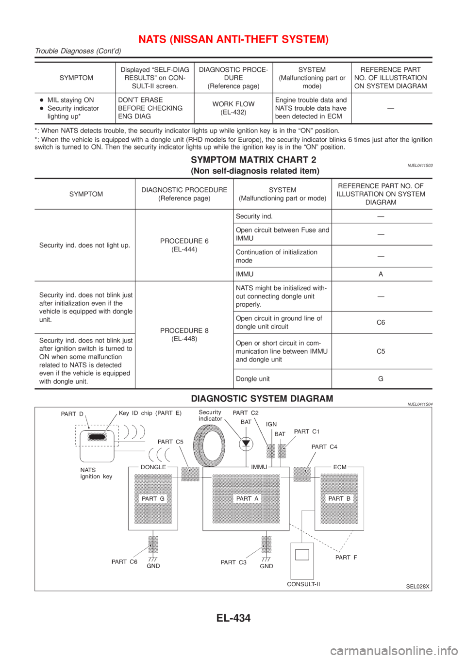
DIAGNOSTIC SYSTEM DIAGRAMNJEL0411S04
SEL028X
NATS (NISSAN ANTI-THEFT SYSTEM)
Trouble Diagnoses (Cont'd)
EL-434
Page 2002 of 2898
![NISSAN ALMERA 2001 Service Manual DIAGNOSTIC PROCEDURE 6=NJEL0411S10ªSECURITY INDICATOR LAMP DOES NOT LIGHT UPº
1 CHECK FUSE
Check 10A fuse [No. 12, located in the fuse block (J/B)].
Is 10A fuse OK?
Ye s©GO TO 2.
No©Replace fuse.
NISSAN ALMERA 2001 Service Manual DIAGNOSTIC PROCEDURE 6=NJEL0411S10ªSECURITY INDICATOR LAMP DOES NOT LIGHT UPº
1 CHECK FUSE
Check 10A fuse [No. 12, located in the fuse block (J/B)].
Is 10A fuse OK?
Ye s©GO TO 2.
No©Replace fuse.](/manual-img/5/57348/w960_57348-2001.png)
DIAGNOSTIC PROCEDURE 6=NJEL0411S10ªSECURITY INDICATOR LAMP DOES NOT LIGHT UPº
1 CHECK FUSE
Check 10A fuse [No. 12, located in the fuse block (J/B)].
Is 10A fuse OK?
Ye s©GO TO 2.
No©Replace fuse.
2 CHECK SECURITY INDICATOR LAMP
1. Install 10A fuse.
2. Perform initialization with CONSULT-II.
For initialization, refer to ªCONSULT-II Operation Manual NATSº.
3. Turn ignition switch OFF.
4. Start engine and turn ignition switch OFF.
5. Check the security indicator lamp lighting.
Security indicator lamp should be light up.
OK or NG
OK©INSPECTION END
NG©GO TO 3.
3 CHECK SECURITY INDICATOR LAMP POWER SUPPLY CIRCUIT
1. Disconnect security indicator lamp connector (models before VIN No. Ð N16U0135126) or Combination meter connec-
tor (models after VIN No. Ð N16U0135126).
2. Check voltage between security indicator lamp connector terminal 2 and ground (models before VIN No. Ð
N16U0135126), or Check voltage between combination meter (security indicator lamp) connector terminal 23 and
ground (models after VIN No. Ð N16U0135126).
YEL787C
OK or NG
OK©GO TO 4.
NG©Check harness for open or short between fuse and security indicator lamp (models
before VIN No. Ð N16U0135126) or Combination meter (models after VIN No. Ð
N16U0135126).
4 CHECK SECURITY INDICATOR LAMP
Check security Indicator Lamp.
Is security indicator lamp OK?
Ye s©GO TO 5.
No©Repair or replace combination meter or security indicator lamp.
NATS (NISSAN ANTI-THEFT SYSTEM)
Trouble Diagnoses (Cont'd)
EL-444
Page 2041 of 2898
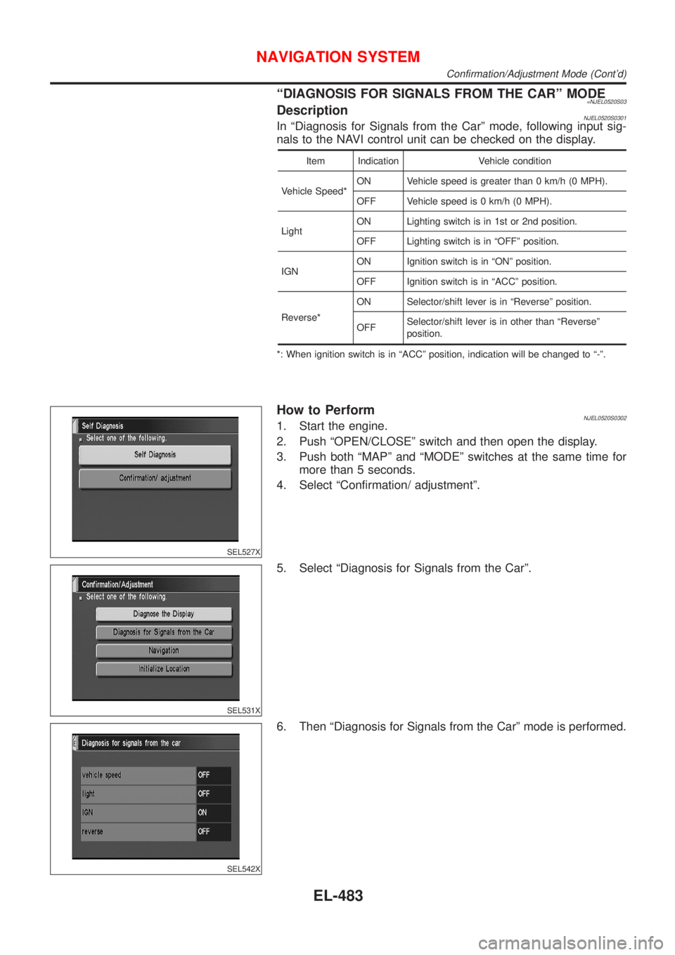
ªDIAGNOSIS FOR SIGNALS FROM THE CARº MODE=NJEL0520S03DescriptionNJEL0520S0301In ªDiagnosis for Signals from the Carº mode, following input sig-
nals to the NAVI control unit can be checked on the display.
Item Indication Vehicle condition
Vehicle Speed*ON Vehicle speed is greater than 0 km/h (0 MPH).
OFF Vehicle speed is 0 km/h (0 MPH).
LightON Lighting switch is in 1st or 2nd position.
OFF Lighting switch is in ªOFFº position.
IGNON Ignition switch is in ªONº position.
OFF Ignition switch is in ªACCº position.
Reverse*ON Selector/shift lever is in ªReverseº position.
OFFSelector/shift lever is in other than ªReverseº
position.
*: When ignition switch is in ªACCº position, indication will be changed to ª-º.
SEL527X
How to PerformNJEL0520S03021. Start the engine.
2. Push ªOPEN/CLOSEº switch and then open the display.
3. Push both ªMAPº and ªMODEº switches at the same time for
more than 5 seconds.
4. Select ªConfirmation/ adjustmentº.
SEL531X
5. Select ªDiagnosis for Signals from the Carº.
SEL542X
6. Then ªDiagnosis for Signals from the Carº mode is performed.
NAVIGATION SYSTEM
Confirmation/Adjustment Mode (Cont'd)
EL-483
Page 2239 of 2898
JEM143G
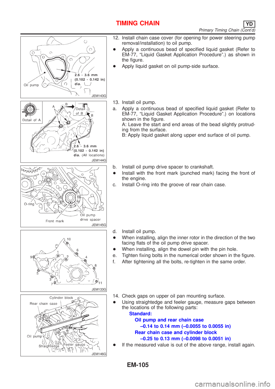
12. Install chain case cover (for opening for power steering pump
removal/installation) to oil pump.
+Apply a continuous bead of specified liquid gasket (Refer to
EM-77, ªLiquid Gasket Application Procedureº.) as shown in
the figure.
+Apply liquid gasket on oil pump-side surface.
JEM144G
13. Install oil pump.
a. Apply a continuous bead of specified liquid gasket (Refer to
EM-77, ªLiquid Gasket Application Procedureº.) on locations
shown in the figure.
A: Leave the start and end areas of the bead slightly protrud-
ing from the surface.
B: Apply liquid gasket along upper end surface of oil pump.
JEM145G
b. Install oil pump drive spacer to crankshaft.
+Install with the front mark (punched mark) facing the front of
the engine.
c. Install O-ring into the groove of rear chain case.
JEM133G
d. Install oil pump.
+When installing, align the inner rotor in the direction of the two
facing flats of the oil pump drive spacer.
+When installing, align the dowel pin with the pin hole.
e. Tighten fixing bolts in the numerical order shown in the figure.
f. After tightening all the bolts, re-tighten in the same order.
JEM146G
14. Check gaps on upper oil pan mounting surface.
+Using straightedge and feeler gauge, measure gaps between
the locations of the following parts:
Standard:
Oil pump and rear chain case
±0.14 to 0.14 mm (±0.0055 to 0.0055 in)
Rear chain case and cylinder block
±0.25 to 0.13 mm (±0.0098 to 0.0051 in)
+If the measured value is out of the above range, install again.
TIMING CHAINYD
Primary Timing Chain (Cont'd)
EM-105
Page 2368 of 2898
Incident Simulation TestsNJGI0005S02INTRODUCTIONNJGI0005S0201Sometimes the symptom is not present when the vehicle is brought
in for service. If possible, re-create the conditions present at the
time of the incident. Doing so may help avoid a No Trouble Found
Diagnoses. The following section illustrates ways to simulate the
conditions/environment under which the owner experiences an
electrical incident.
The section is broken into the six following topics:
+Vehicle vibration
+Heat sensitive
+Freezing
+Water intrusion
+Electrical load
+Cold or hot start up
Get a thorough description of the incident from the customer. It is
important for simulating the conditions of the problem.
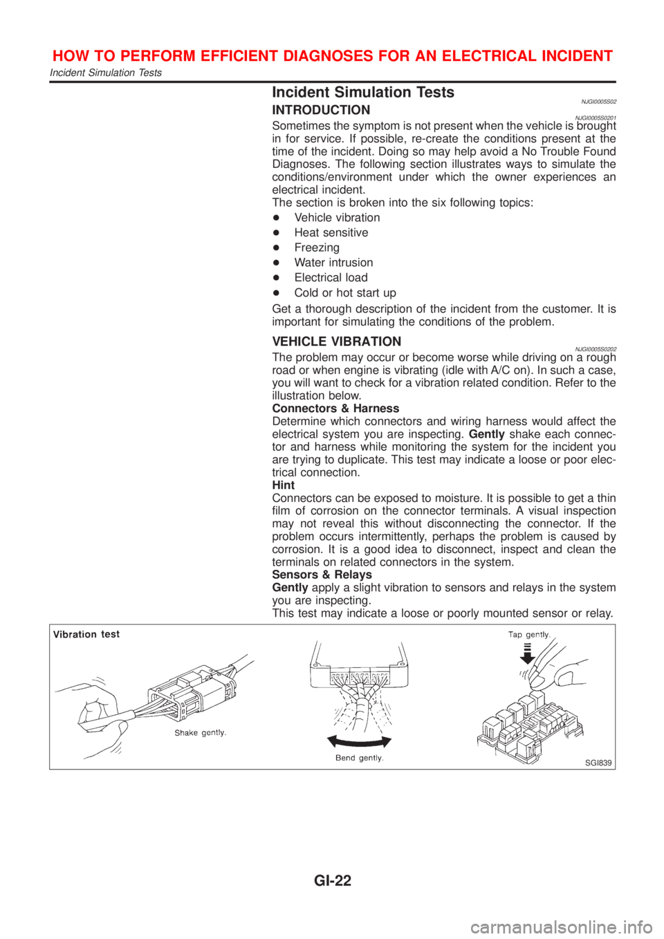
VEHICLE VIBRATIONNJGI0005S0202The problem may occur or become worse while driving on a rough
road or when engine is vibrating (idle with A/C on). In such a case,
you will want to check for a vibration related condition. Refer to the
illustration below.
Connectors & Harness
Determine which connectors and wiring harness would affect the
electrical system you are inspecting.Gentlyshake each connec-
tor and harness while monitoring the system for the incident you
are trying to duplicate. This test may indicate a loose or poor elec-
trical connection.
Hint
Connectors can be exposed to moisture. It is possible to get a thin
film of corrosion on the connector terminals. A visual inspection
may not reveal this without disconnecting the connector. If the
problem occurs intermittently, perhaps the problem is caused by
corrosion. It is a good idea to disconnect, inspect and clean the
terminals on related connectors in the system.
Sensors & Relays
Gentlyapply a slight vibration to sensors and relays in the system
you are inspecting.
This test may indicate a loose or poorly mounted sensor or relay.
SGI839
HOW TO PERFORM EFFICIENT DIAGNOSES FOR AN ELECTRICAL INCIDENT
Incident Simulation Tests
GI-22