Page 1289 of 2898

3 DETECT MALFUNCTIONING PART
Check the following.
+10A fuse
+15A fuse
+Harness for open or short between fuse and fuel pump relay
©Repair harness or connectors.
4 CHECK POWER GROUND CIRCUIT
1. Turn ignition switch ªOFFº.
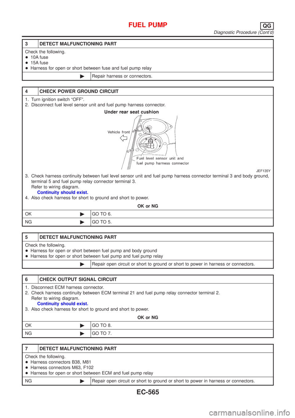
2. Disconnect fuel level sensor unit and fuel pump harness connector.
JEF135Y
3. Check harness continuity between fuel level sensor unit and fuel pump harness connector terminal 3 and body ground,
terminal 5 and fuel pump relay connector terminal 3.
Refer to wiring diagram.
Continuity should exist.
4. Also check harness for short to ground and short to power.
OK or NG
OK©GO TO 6.
NG©GO TO 5.
5 DETECT MALFUNCTIONING PART
Check the following.
+Harness for open or short between fuel pump and body ground
+Harness for open or short between fuel pump and fuel pump relay
©Repair open circuit or short to ground or short to power in harness or connectors.
6 CHECK OUTPUT SIGNAL CIRCUIT
1. Disconnect ECM harness connector.
2. Check harness continuity between ECM terminal 21 and fuel pump relay connector terminal 2.
Refer to wiring diagram.
Continuity should exist.
3. Also check harness for short to ground and short to power.
OK or NG
OK©GO TO 8.
NG©GO TO 7.
7 DETECT MALFUNCTIONING PART
Check the following.
+Harness connectors B38, M81
+Harness connectors M63, F102
+Harness for open or short between ECM and fuel pump relay
NG©Repair open circuit or short to ground or short to power in harness or connectors.
FUEL PUMPQG
Diagnostic Procedure (Cont'd)
EC-565
Page 1290 of 2898
8 CHECK FUEL PUMP RELAY
Refer to ªComponent Inspectionº, EC-566.
OK or NG
OK©GO TO 9.
NG©Replace fuel pump relay.
9 CHECK FUEL PUMP
Refer to ªComponent Inspectionº, EC-566.
OK or NG
OK©GO TO 10.
NG©Replace fuel pump.
10 CHECK INTERMITTENT INCIDENT
Perform ªTROUBLE DIAGNOSIS FOR INTERMITTENT INCIDENTº, EC-177.
©INSPECTION END
SEF145X
Component InspectionNJEC0449FUEL PUMP RELAYNJEC0449S01Check continuity between terminals 3 and 5.
Conditions Continuity
12V direct current supply between terminals 1 and 2 Yes
No current supply No
If NG, replace relay.
JEF136Y
FUEL PUMPNJEC0449S021. Disconnect fuel level sensor unit and fuel pump harness con-
nector.
2. Check resistance between terminals 3 and 5.
Resistance: 0.2 - 5.0W[at 25ÉC (77ÉF)]
If NG, replace fuel pump.
FUEL PUMPQG
Diagnostic Procedure (Cont'd)
EC-566
Page 1296 of 2898

JEF147Y
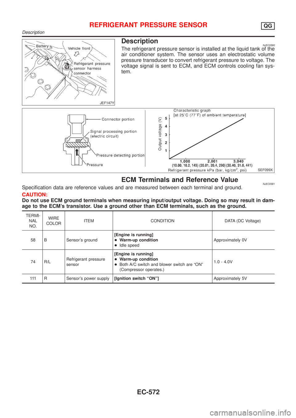
DescriptionNJEC0580The refrigerant pressure sensor is installed at the liquid tank of the
air conditioner system. The sensor uses an electrostatic volume
pressure transducer to convert refrigerant pressure to voltage. The
voltage signal is sent to ECM, and ECM controls cooling fan sys-
tem.
SEF099X
ECM Terminals and Reference ValueNJEC0581Specification data are reference values and are measured between each terminal and ground.
CAUTION:
Do not use ECM ground terminals when measuring input/output voltage. Doing so may result in dam-
age to the ECM's transistor. Use a ground other than ECM terminals, such as the ground.
TERMI-
NAL
NO.WIRE
COLORITEM CONDITION DATA (DC Voltage)
58 B Sensor's ground[Engine is running]
+Warm-up condition
+Idle speedApproximately 0V
74 R/LRefrigerant pressure
sensor[Engine is running]
+Warm-up condition
+Both A/C switch and blower switch are ªONº
(Compressor operates.)1.0 - 4.0V
111 R Sensor's power supply[Ignition switch ªONº]Approximately 5V
REFRIGERANT PRESSURE SENSORQG
Description
EC-572
Page 1297 of 2898
Wiring DiagramNJEC0582SEDAN MODELS AND HATCHBACK MODELS WITH ECM IN ENGINE COMPARTMENTNJEC0582S03
HEC806
REFRIGERANT PRESSURE SENSORQG
Wiring Diagram
EC-573
Page 1298 of 2898
HATCHBACK MODELS WITH ECM IN CABINNJEC0582S04
HEC961
REFRIGERANT PRESSURE SENSORQG
Wiring Diagram (Cont'd)
EC-574
Page 1299 of 2898
Diagnostic ProcedureNJEC0590
1 CHECK REFRIGERANT PRESSURE SENSOR OVERALL FUNCTION
1. Start engine and warm it up to normal operating temperature.
2. Turn A/C switch and blower switch ªONº.
3. Check voltage between ECM terminal 74 and ground with CONSULT-II or tester.
SEF952XA
OK or NG
OK©INSPECTION END
NG©GO TO 2.
2 CHECK REFRIGERANT PRESSURE SENSOR POWER SUPPLY CIRCUIT
1. Turn A/C switch and blower switch ªOFFº.
2. Stop engine.
3. Disconnect refrigerant pressure sensor harness connector.
JEF147Y
4. Turn ignition switch ªONº.
5. Check voltage between refrigerant pressure sensor terminal 3 and ground with CONSULT-II or tester.
SEF953X
OK or NG
OK©GO TO 4.
NG©GO TO 3.
REFRIGERANT PRESSURE SENSORQG
Diagnostic Procedure
EC-575
Page 1300 of 2898

3 DETECT MALFUNCTIONING PART
Check the following.
+Harness connectors E75, F36
+Joint connector-4 (If so equipped)
+Joint connector-6 (If so equipped)
+Harness for open or short between ECM and refrigerant pressure sensor
©Repair harness or connectors.
4 CHECK REFRIGERANT PRESSURE SENSOR GROUND CIRCUIT
1. Turn ignition switch ªOFFº.
2. Check harness continuity between refrigerant pressure sensor terminal 1 and engine ground. Refer to Wiring Diagram.
Continuity should exist.
3. Also check harness for short to ground and short to power.
OK or NG
OK©GO TO 6.
NG©GO TO 5.
5 DETECT MALFUNCTIONING PART
Check the following.
+Harness connectors E75, F36
+Joint connector-3 (If so equipped)
+Joint connector-6 (If so equipped)
+Harness for open or short between ECM and refrigerant pressure sensor
+Harness for open or short between TCM (Transmission Control Module) and refrigerant pressure sensor
©Repair open circuit or short to ground or short to power in harness or connectors.
6 CHECK REFRIGERANT PRESSURE SENSOR INPUT SIGNAL CIRCUIT
1. Disconnect ECM harness connector.
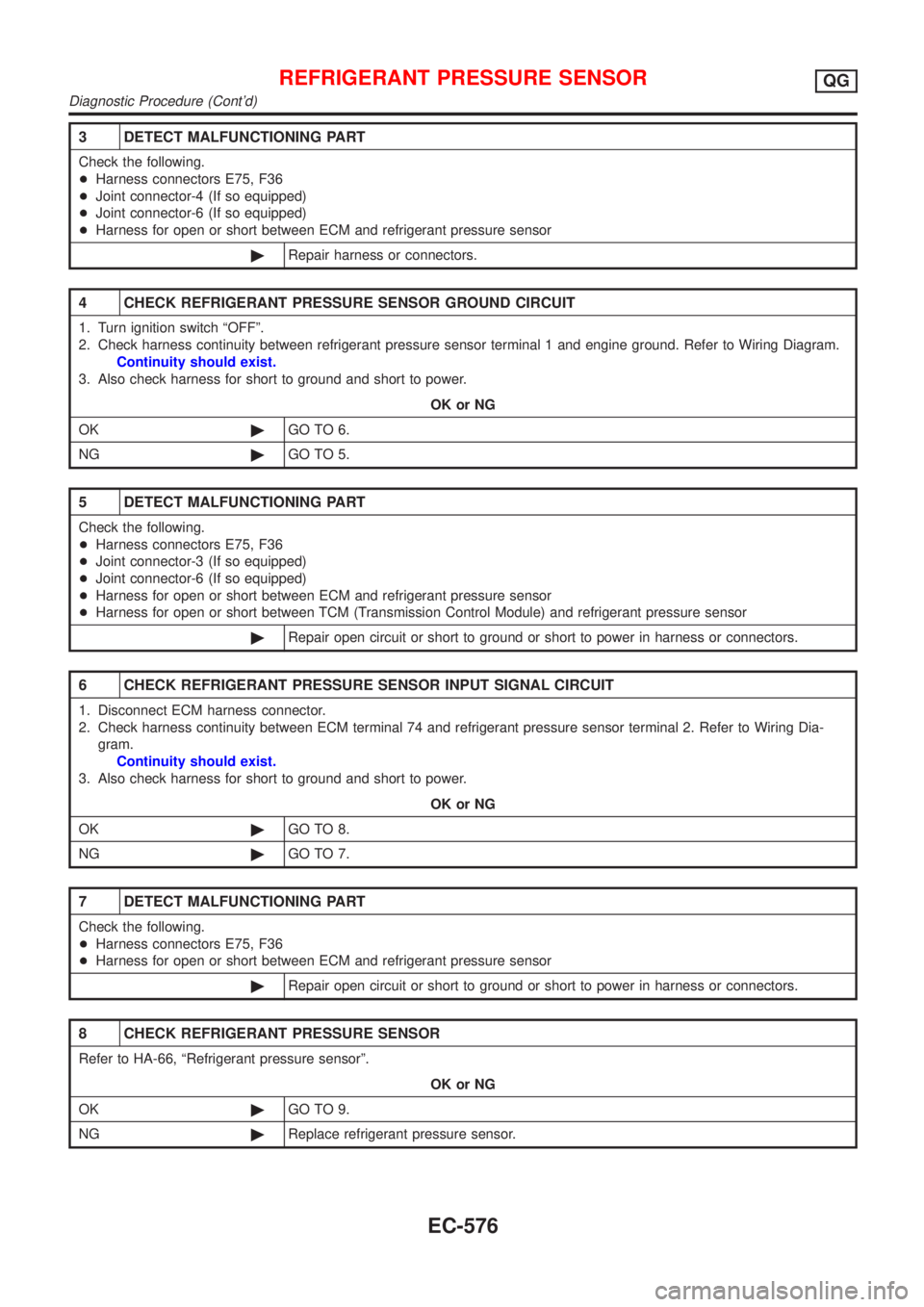
2. Check harness continuity between ECM terminal 74 and refrigerant pressure sensor terminal 2. Refer to Wiring Dia-
gram.
Continuity should exist.
3. Also check harness for short to ground and short to power.
OK or NG
OK©GO TO 8.
NG©GO TO 7.
7 DETECT MALFUNCTIONING PART
Check the following.
+Harness connectors E75, F36
+Harness for open or short between ECM and refrigerant pressure sensor
©Repair open circuit or short to ground or short to power in harness or connectors.
8 CHECK REFRIGERANT PRESSURE SENSOR
Refer to HA-66, ªRefrigerant pressure sensorº.
OK or NG
OK©GO TO 9.
NG©Replace refrigerant pressure sensor.
REFRIGERANT PRESSURE SENSORQG
Diagnostic Procedure (Cont'd)
EC-576
Page 1301 of 2898
9 CHECK INTERMITTENT INCIDENT
Refer to ªTROUBLE DIAGNOSIS FOR INTERMITTENT INCIDENTº, EC-177.
©INSPECTION END
REFRIGERANT PRESSURE SENSORQG
Diagnostic Procedure (Cont'd)
EC-577