Page 1014 of 2898
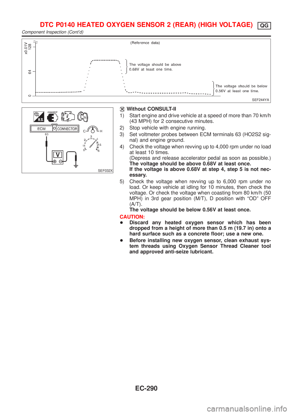
SEF244YA
SEF032X
Without CONSULT-II
1) Start engine and drive vehicle at a speed of more than 70 km/h
(43 MPH) for 2 consecutive minutes.
2) Stop vehicle with engine running.
3) Set voltmeter probes between ECM terminals 63 (HO2S2 sig-
nal) and engine ground.
4) Check the voltage when revving up to 4,000 rpm under no load
at least 10 times.
(Depress and release accelerator pedal as soon as possible.)
The voltage should be above 0.68V at least once.
If the voltage is above 0.68V at step 4, step 5 is not nec-
essary.
5) Check the voltage when revving up to 6,000 rpm under no
load. Or keep vehicle at idling for 10 minutes, then check the
voltage. Or check the voltage when coasting from 80 km/h (50
MPH) in 3rd gear position (M/T), D position with ªODº OFF
(A/T).
The voltage should be below 0.56V at least once.
CAUTION:
+Discard any heated oxygen sensor which has been
dropped from a height of more than 0.5 m (19.7 in) onto a
hard surface such as a concrete floor; use a new one.
+Before installing new oxygen sensor, clean exhaust sys-
tem threads using Oxygen Sensor Thread Cleaner tool
and approved anti-seize lubricant.
DTC P0140 HEATED OXYGEN SENSOR 2 (REAR) (HIGH VOLTAGE)QG
Component Inspection (Cont'd)
EC-290
Page 1015 of 2898
DescriptionNJEC0180SYSTEM DESCRIPTIONNJEC0180S01
Sensor Input Signal to ECMECM func-
tionActuator
Camshaft position sensor (PHASE)
Crankshaft position sensor (POS)Engine speedHeated
oxygen
sensor 2
heater
(rear) con-
trolHeated oxygen sensor 2 heater
(rear)
The ECM performs ON/OFF control of the heated oxygen sensor 2 heater (rear) corresponding to the engine
speed.
OPERATIONNJEC0180S02
Engine condition Heated oxygen sensor 2 heater (rear)
Engine stopped OFF
Engine is running. After driving for 2 minutes at a speed
of 70 km/h (43 MPH) or moreON
Engine speed above 3,600 rpm OFF
CONSULT-II Reference Value in Data Monitor
Mode
NJEC0181Specification data are reference values.
MONITOR ITEM CONDITION SPECIFICATION
HO2S2 HTR (B1)+Engine speedBelow 3,600 rpm [After driving for 2 minutes at a
speed of 70 km/h (43 MPH) or more]ON
Above 3,600 rpm OFF
+Ignition switch ON (Engine stopped) OFF
ECM Terminals and Reference ValueNJEC0182Specification data are reference values and are measured between each terminal and ground.
CAUTION:
Do not use ECM ground terminals when measuring input/output voltage. Doing so may result in dam-
age to the ECM's transistor. Use a ground other than ECM terminals, such as the ground.
TERMI-
NAL NO.WIRE
COLORITEM CONDITION DATA (DC Voltage)
3 W/RHeated oxygen sensor 2
heater (rear)[Engine is running]
+Engine speed is below 3,600 rpm [After driving
for 2 minutes at a speed of 70 km/h (43 MPH) or
more]Approximately 0.7V
[Engine is running]
+Engine speed is above 3,600 rpm
BATTERY VOLTAGE
(11 - 14V)
[Ignition switch ªONº]
+Engine stopped
DTC P0141 HEATED OXYGEN SENSOR 2 HEATER (REAR)QG
Description
EC-291
Page 1016 of 2898
On Board Diagnosis LogicNJEC0183
DTC No. Malfunction is detected when ... Check Items (Possible Cause)
P0141
0141+The current amperage in the heated oxygen sensor 2
heater (rear) circuit is out of the normal range.
[An improper voltage drop signal is sent to ECM through
the heated oxygen sensor 2 heater (rear).]+Harness or connectors
(The heated oxygen sensor 2 heater (rear) cir-
cuit is open or shorted.)
+Heated oxygen sensor 2 heater (rear)
DTC Confirmation ProcedureNJEC0184NOTE:
If ªDTC Confirmation Procedure º has been previously conducted,
always turn ignition switch ªOFFº and wait at least 9 seconds
before conducting the next test.
TESTING CONDITION:
Before performing the following procedure, confirm that bat-
tery voltage is in between 10.5V and 16V at idle.
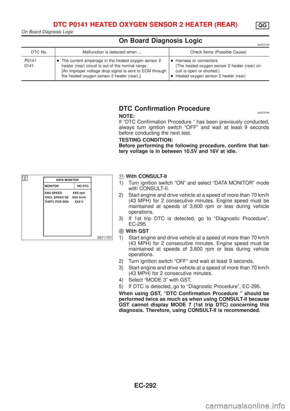
SEF175Y
With CONSULT-II
1) Turn ignition switch ªONº and select ªDATA MONITORº mode
with CONSULT-II.
2) Start engine and drive vehicle at a speed of more than 70 km/h
(43 MPH) for 2 consecutive minutes. Engine speed must be
maintained at speeds of 3,600 rpm or less during vehicle
operations.
3) If 1st trip DTC is detected, go to ªDiagnostic Procedureº,
EC-295.
With GST
1) Start engine and drive vehicle at a speed of more than 70 km/h
(43 MPH) for 2 consecutive minutes. Engine speed must be
maintained at speeds of 3,600 rpm or less during vehicle
operations.
2) Turn ignition switch ªOFFº and wait at least 9 seconds.
3) Start engine and drive vehicle at a speed of more than 70 km/h
(43 MPH) for 2 consecutive minutes.
4) Select ªMODE 3º with GST.
5) If DTC is detected, go to ªDiagnostic Procedureº, EC-295.
When using GST, ªDTC Confirmation Procedure º should be
performed twice as much as when using CONSULT-II because
GST cannot display MODE 7 (1st trip DTC) concerning this
diagnosis. Therefore, using CONSULT-II is recommended.
DTC P0141 HEATED OXYGEN SENSOR 2 HEATER (REAR)QG
On Board Diagnosis Logic
EC-292
Page 1017 of 2898
Wiring DiagramNJEC0185SEDAN MODELS AND HATCHBACK MODELS WITH
ECM IN ENGINE COMPARTMENT
NJEC0185S03
HEC788
DTC P0141 HEATED OXYGEN SENSOR 2 HEATER (REAR)QG
Wiring Diagram
EC-293
Page 1021 of 2898
On Board Diagnosis LogicNJEC0188With the Air/Fuel Mixture Ratio Self-Learning Control, the actual mixture ratio can be brought closely to the
theoretical mixture ratio based on the mixture ratio feedback signal from the heated oxygen sensor 1 (front).
The ECM calculates the necessary compensation to correct the offset between the actual and the theoretical
ratios.
In case the amount of the compensation value is extremely large (The actual mixture ratio is too lean.), the
ECM judges the condition as the fuel injection system malfunction and lights up the MIL (2 trip detection logic).
Sensor Input Signal to ECMECM func-
tionActuator
Heated oxygen sensor 1 (front)Density of oxygen in exhaust gas
(Mixture ratio feedback signal)Fuel injec-
tion & mix-
ture ratio
controlInjectors
DTC No. Malfunction is detected when ... Check Items (Possible Cause)
P0171
0171+Fuel injection system does not operate properly.
+The amount of mixture ratio compensation is too large.
(The mixture ratio is too lean.)+Intake air leaks
+Heated oxygen sensor 1 (front)
+Injectors
+Exhaust gas leaks
+Incorrect fuel pressure
+Lack of fuel
+Mass air flow sensor
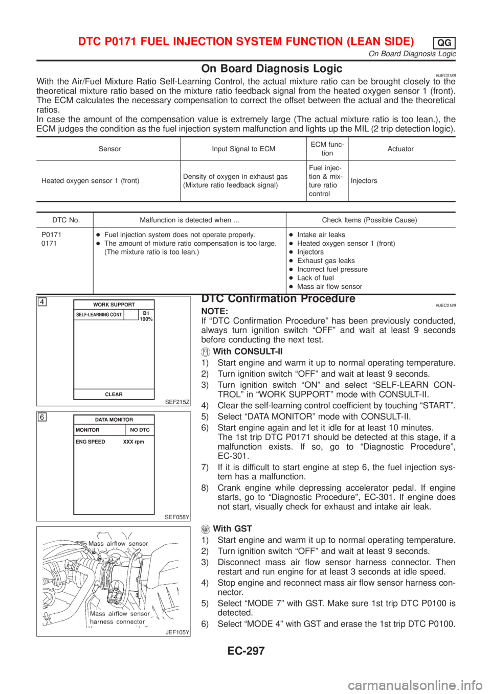
SEF215Z
SEF058Y
DTC Confirmation ProcedureNJEC0189NOTE:
If ªDTC Confirmation Procedureº has been previously conducted,
always turn ignition switch ªOFFº and wait at least 9 seconds
before conducting the next test.
With CONSULT-II
1) Start engine and warm it up to normal operating temperature.
2) Turn ignition switch ªOFFº and wait at least 9 seconds.
3) Turn ignition switch ªONº and select ªSELF-LEARN CON-
TROLº in ªWORK SUPPORTº mode with CONSULT-II.
4) Clear the self-learning control coefficient by touching ªSTARTº.
5) Select ªDATA MONITORº mode with CONSULT-II.
6) Start engine again and let it idle for at least 10 minutes.
The 1st trip DTC P0171 should be detected at this stage, if a
malfunction exists. If so, go to ªDiagnostic Procedureº,
EC-301.
7) If it is difficult to start engine at step 6, the fuel injection sys-
tem has a malfunction.
8) Crank engine while depressing accelerator pedal. If engine
starts, go to ªDiagnostic Procedureº, EC-301. If engine does
not start, visually check for exhaust and intake air leak.
JEF105Y
With GST
1) Start engine and warm it up to normal operating temperature.
2) Turn ignition switch ªOFFº and wait at least 9 seconds.
3) Disconnect mass air flow sensor harness connector. Then
restart and run engine for at least 3 seconds at idle speed.
4) Stop engine and reconnect mass air flow sensor harness con-
nector.
5) Select ªMODE 7º with GST. Make sure 1st trip DTC P0100 is
detected.
6) Select ªMODE 4º with GST and erase the 1st trip DTC P0100.
DTC P0171 FUEL INJECTION SYSTEM FUNCTION (LEAN SIDE)QG
On Board Diagnosis Logic
EC-297
Page 1022 of 2898
7) Start engine again and run it for at least 10 minutes at idle
speed.
8) Select ªMODE 7º with GST. The 1st trip DTC P0171 should be
detected at this stage, if a malfunction exists. If so, go to
ªDiagnostic Procedureº, EC-301.
9) If it is difficult to start engine at step 8, the fuel injection sys-
tem has a malfunction.
10) Crank engine while depressing accelerator pedal. If engine
starts, go to ªDiagnostic Procedureº, EC-301. If engine does
not start, visually check for exhaust and intake air leak.
DTC P0171 FUEL INJECTION SYSTEM FUNCTION (LEAN SIDE)QG
DTC Confirmation Procedure (Cont'd)
EC-298
Page 1023 of 2898
Wiring DiagramNJEC0190SEDAN MODELS AND HATCHBACK MODELS WITH
ECM IN ENGINE COMPARTMENT
NJEC0190S03
HEC789
DTC P0171 FUEL INJECTION SYSTEM FUNCTION (LEAN SIDE)QG
Wiring Diagram
EC-299
Page 1025 of 2898
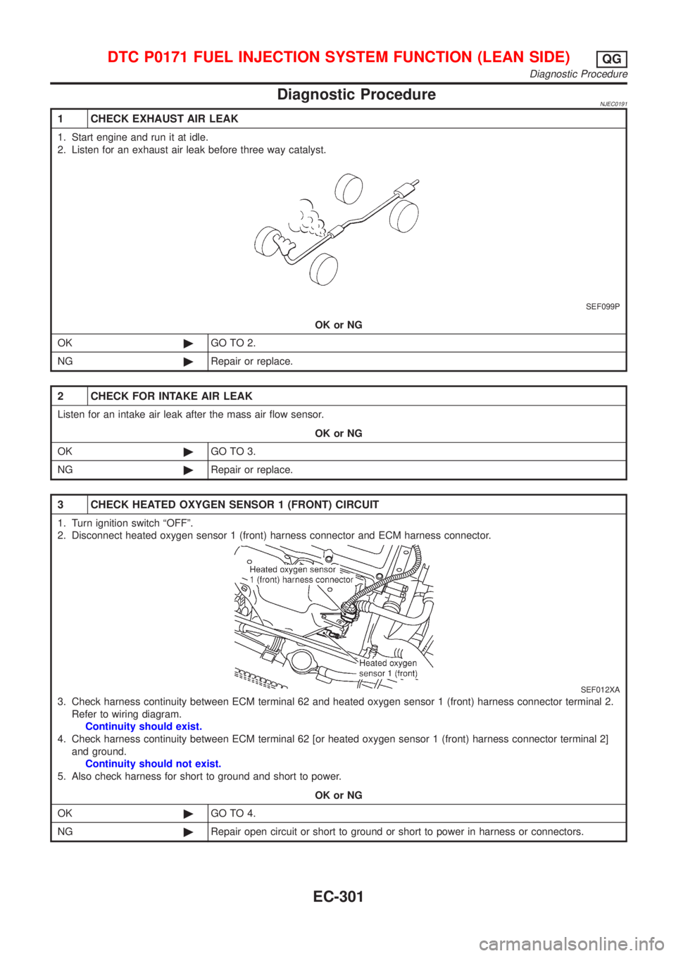
Diagnostic ProcedureNJEC0191
1 CHECK EXHAUST AIR LEAK
1. Start engine and run it at idle.
2. Listen for an exhaust air leak before three way catalyst.
SEF099P
OK or NG
OK©GO TO 2.
NG©Repair or replace.
2 CHECK FOR INTAKE AIR LEAK
Listen for an intake air leak after the mass air flow sensor.
OK or NG
OK©GO TO 3.
NG©Repair or replace.
3 CHECK HEATED OXYGEN SENSOR 1 (FRONT) CIRCUIT
1. Turn ignition switch ªOFFº.
2. Disconnect heated oxygen sensor 1 (front) harness connector and ECM harness connector.
SEF012XA
3. Check harness continuity between ECM terminal 62 and heated oxygen sensor 1 (front) harness connector terminal 2.
Refer to wiring diagram.
Continuity should exist.
4. Check harness continuity between ECM terminal 62 [or heated oxygen sensor 1 (front) harness connector terminal 2]
and ground.
Continuity should not exist.
5. Also check harness for short to ground and short to power.
OK or NG
OK©GO TO 4.
NG©Repair open circuit or short to ground or short to power in harness or connectors.
DTC P0171 FUEL INJECTION SYSTEM FUNCTION (LEAN SIDE)QG
Diagnostic Procedure
EC-301