Page 779 of 2898
26 CHECK ªCOº %
1. Start engine and warm it up until engine coolant temperature indicator points to the middle of gauge.
SEF090Y
2. Rev engine (2,000 to 3,000 rpm) two or three times under no-load, then run engine at idle speed.
SEF978U
3. Check ªCOº %.
Idle CO:3-11%
4.
Without CONSULT-II
After checking CO%,
a. Disconnect the resistor from terminals of engine coolant temperature sensor.
b. Connect engine coolant temperature sensor harness connector to engine coolant temperature sensor.
OK or NG
OK©GO TO 27.
NG©GO TO 28.
BASIC SERVICE PROCEDUREQG
Inspection Procedure (Cont'd)
EC-55
Page 1343 of 2898

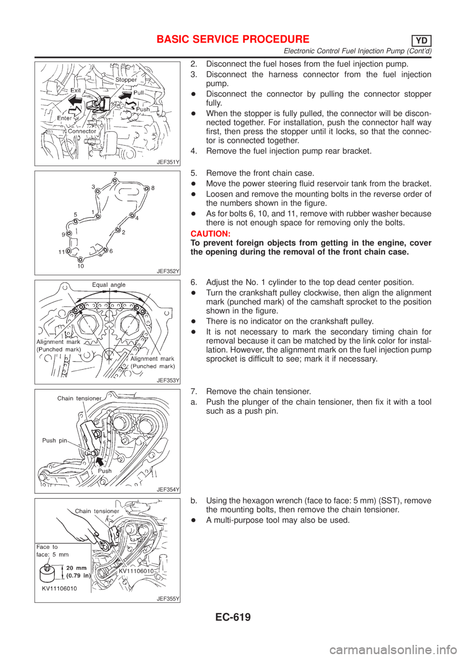
JEF351Y
2. Disconnect the fuel hoses from the fuel injection pump.
3. Disconnect the harness connector from the fuel injection
pump.
+Disconnect the connector by pulling the connector stopper
fully.
+When the stopper is fully pulled, the connector will be discon-
nected together. For installation, push the connector half way
first, then press the stopper until it locks, so that the connec-
tor is connected together.
4. Remove the fuel injection pump rear bracket.
JEF352Y
5. Remove the front chain case.
+Move the power steering fluid reservoir tank from the bracket.
+Loosen and remove the mounting bolts in the reverse order of
the numbers shown in the figure.
+As for bolts 6, 10, and 11, remove with rubber washer because
there is not enough space for removing only the bolts.
CAUTION:
To prevent foreign objects from getting in the engine, cover
the opening during the removal of the front chain case.
JEF353Y
6. Adjust the No. 1 cylinder to the top dead center position.
+Turn the crankshaft pulley clockwise, then align the alignment
mark (punched mark) of the camshaft sprocket to the position
shown in the figure.
+There is no indicator on the crankshaft pulley.
+It is not necessary to mark the secondary timing chain for
removal because it can be matched by the link color for instal-
lation. However, the alignment mark on the fuel injection pump
sprocket is difficult to see; mark it if necessary.
JEF354Y
7. Remove the chain tensioner.
a. Push the plunger of the chain tensioner, then fix it with a tool
such as a push pin.
JEF355Y
b. Using the hexagon wrench (face to face: 5 mm) (SST), remove
the mounting bolts, then remove the chain tensioner.
+A multi-purpose tool may also be used.
BASIC SERVICE PROCEDUREYD
Electronic Control Fuel Injection Pump (Cont'd)
EC-619
Page 2206 of 2898

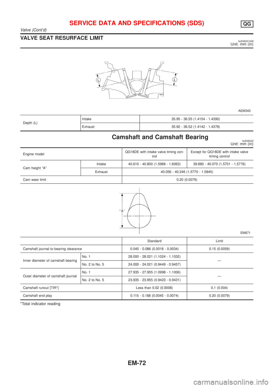
VALVE SEAT RESURFACE LIMITNJEM0031S08Unit: mm (in)
AEM343
Depth (L)Intake 35.95 - 36.55 (1.4154 - 1.4390)
Exhaust 35.92 - 36.52 (1.4142 - 1.4378)
Camshaft and Camshaft BearingNJEM0032Unit: mm (in)
Engine modelQG18DE with intake valve timing con-
trolExcept for QG18DE with intake valve
timing control
Cam height ªAºIntake 40.610 - 40.800 (1.5988 - 1.6063) 39.880 - 40.070 (1.5701 - 1.5776)
Exhaust 40.056 - 40.246 (1.5770 - 1.5845)
Cam wear limit0.20 (0.0079)
EM671
Standard Limit
Camshaft journal to bearing clearance 0.045 - 0.086 (0.0018 - 0.0034) 0.15 (0.0059)
Inner diameter of camshaft bearingNo. 1 28.000 - 28.021 (1.1024 - 1.1032)
Ð
No. 2 to No. 5 24.000 - 24.021 (0.9449 - 0.9457)
Outer diameter of camshaft journalNo. 1 27.935 - 27.955 (1.0998 - 1.1006)
Ð
No. 2 to No. 5 23.935 - 23.955 (0.9423 - 0.9431)
Camshaft runout [TIR*] Less than 0.02 (0.0008) 0.1 (0.004)
Camshaft end play 0.115 - 0.188 (0.0045 - 0.0074) 0.20 (0.0079)
*Total indicator reading
SERVICE DATA AND SPECIFICATIONS (SDS)QG
Valve (Cont'd)
EM-72
Page 2209 of 2898
![NISSAN ALMERA 2001 Service Manual Connecting RodNJEM0035Unit: mm (in)
Center distance140.45 - 140.55 (5.5295 - 5.5335)
Bend limit [per 100 (3.94)]0.15 (0.0059)
Torsion limit [per 100 (3.94)]0.3 (0.012)
Connecting rod bushing inner dia NISSAN ALMERA 2001 Service Manual Connecting RodNJEM0035Unit: mm (in)
Center distance140.45 - 140.55 (5.5295 - 5.5335)
Bend limit [per 100 (3.94)]0.15 (0.0059)
Torsion limit [per 100 (3.94)]0.3 (0.012)
Connecting rod bushing inner dia](/manual-img/5/57348/w960_57348-2208.png)
Connecting RodNJEM0035Unit: mm (in)
Center distance140.45 - 140.55 (5.5295 - 5.5335)
Bend limit [per 100 (3.94)]0.15 (0.0059)
Torsion limit [per 100 (3.94)]0.3 (0.012)
Connecting rod bushing inner diameter* (small end) 19.000 - 19.012 (0.7480 - 0.7485)
Connecting rod big end inner diameter 43.000 - 43.013 (1.6929 - 1.6934)
Side clearanceStandard 0.200 - 0.470 (0.0079 - 0.0185)
Limit 0.5 (0.020)
*After installing in connecting rod
CrankshaftNJEM0036Unit: mm (in)
Main journal dia. ªDmºGrade No. 0 49.956 - 49.964 (1.9668 - 1.9671)
Grade No. 1 49.948 - 49.956 (1.9665 - 1.9668)
Grade No. 2 49.940 - 49.948 (1.9661 - 1.9665)
Pin journal dia. ªDpºGrade No. 0 39.968 - 39.974 (1.5735 - 1.5738)
Grade No. 1 39.962 - 39.968 (1.5733 - 1.5735)
Grade No. 2 39.956 - 39.962 (1.5731 - 1.5733)
Center distance ªrº43.95 - 44.05 (1.7303 - 1.7342)
Out-of-round (X þ Y)Standard Less than 0.003 (0.0001)
Limit Less than 0.005 (0.0002)
Taper (A þ B)Standard Less than 0.004 (0.0002)
Limit Less than 0.005 (0.0002)
Runout [TIR*]Standard Less than 0.04 (0.0016)
Limit Less than 0.05 (0.0020)
Free end playStandard 0.060 - 0.220 (0.0024 - 0.0087)
Limit 0.3 (0.012)
*: Total indicator reading
Main BearingNJEM0037STANDARDNJEM0037S01
Grade No. Thickness ªTº mm (in) Identification color
0 1.826 - 1.830 (0.0719 - 0.0720) Black
1 1.830 - 1.834 (0.0720 - 0.0722) Brown or Red
2 1.834 - 1.838 (0.0722 - 0.0724) Green
3 1.838 - 1.842 (0.0724 - 0.0725) Yellow
4 1.842 - 1.846 (0.0725 - 0.0727) Blue
UNDERSIZENJEM0037S02Unit: mm (in)
Thickness ªTº
0.25 (0.0098) 1.960 - 1.964 (0.0772 - 0.0773)
0.50 (0.0197) 2.085 - 2.089 (0.0821 - 0.0822)
SERVICE DATA AND SPECIFICATIONS (SDS)QG
Connecting Rod
EM-75
Page 2210 of 2898
Connecting Rod BearingNJEM0038STANDARD SIZENJEM0038S01Unit: mm (in)
Grade No. Thickness Identification color or number
0 1.503 - 1.506 (0.0592 - 0.0593) Ð
1 1.506 - 1.509 (0.0593 - 0.0594) Brown
2 1.509 - 1.512 (0.0594 - 0.0595) Green
UNDERSIZENJEM0038S02Unit: mm (in)
Grade No. Thickness Identification color or number
0.08 (0.0031) 1.542 - 1.546 (0.0607 - 0.0609) Ð
0.12 (0.0047) 1.562 - 1.566 (0.0615 - 0.0617) Ð
0.25 (0.0098) 1.627 - 1.631 (0.0641 - 0.0642) Ð
Bearing ClearanceNJEM0039Unit: mm (in)
Main bearing clearanceStandard 0.020 - 0.044 (0.0008 - 0.0017)
Limit 0.1 (0.004)
Connecting rod bearing clearanceStandard 0.014 - 0.039 (0.0006 - 0.0015)
Limit 0.1 (0.004)
Miscellaneous ComponentsNJEM0040Unit: mm (in)
Flywheel runout [TIR*]Less than 0.15 (0.0059)
Drive plate runout [TIR*]Less than 0.2 (0.008)
Camshaft sprocket runout [TIR*] Less than 0.15 (0.0059)
*: Total indicator reading
SERVICE DATA AND SPECIFICATIONS (SDS)QG
Connecting Rod Bearing
EM-76
Page 2300 of 2898
Camshaft and Camshaft Bearing=NJEM0080Unit: mm (in)
Standard Limit
Camshaft journal to bearing clearance 0.045 - 0.086 (0.0018 - 0.0034) 0.045 - 0.086 (0.0018 - 0.0034)
Inner diameter of camshaft bearingNo. 1
30.500 - 30.521 (1.2008 - 1.2016)
No. 2, 3, 4, 5
24.000 - 24.021 (0.9449 - 0.9457)Ð
Outer diameter of camshaft journalNo. 1
30.435 - 30.455 (1.1982 - 1.1990)
No. 2, 3, 4, 5
23.935 - 23.955 (0.9423 - 0.9431)Ð
Camshaft runout [TIR*] Ð 0.02 (0.0008)
Camshaft sprocket runout [TIR*] Less than 0.15 (0.0059) Ð
Camshaft end play 0.070 - 0.148 (0.0028 - 0.0058) 0.24 (0.0094)
*: Total indicator reading
EM671
Cam height ªAºIntake 39.505 - 39.695 (1.5553 - 1.5628)
Exhaust 39.905 - 40.095 (1.5711 - 1.5785)
Wear limit of cam height 0.15 (0.0059)
Valve timing
EM120
Unit: degree
a bcde f
224 212 2 30 ±2 46
SERVICE DATA AND SPECIFICATIONS (SDS)YD
Camshaft and Camshaft Bearing
EM-166
Page 2303 of 2898

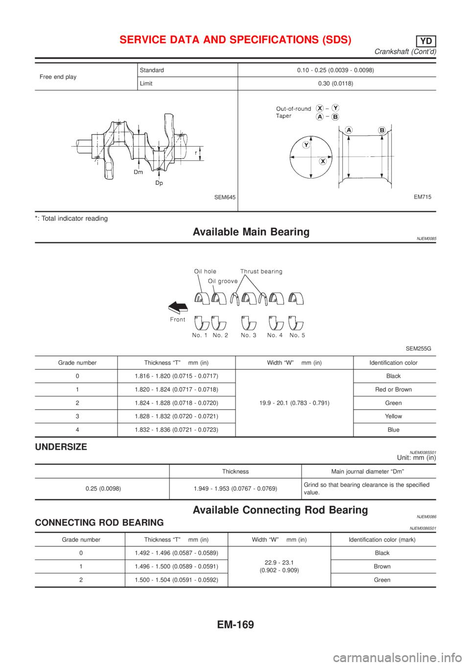
Free end playStandard 0.10 - 0.25 (0.0039 - 0.0098)
Limit 0.30 (0.0118)
SEM645EM715
*: Total indicator reading
Available Main BearingNJEM0085
SEM255G
Grade number Thickness ªTº mm (in) Width ªWº mm (in) Identification color
0 1.816 - 1.820 (0.0715 - 0.0717)
19.9 - 20.1 (0.783 - 0.791)Black
1 1.820 - 1.824 (0.0717 - 0.0718) Red or Brown
2 1.824 - 1.828 (0.0718 - 0.0720) Green
3 1.828 - 1.832 (0.0720 - 0.0721) Yellow
4 1.832 - 1.836 (0.0721 - 0.0723) Blue
UNDERSIZENJEM0085S01Unit: mm (in)
Thickness Main journal diameter ªDmº
0.25 (0.0098) 1.949 - 1.953 (0.0767 - 0.0769)Grind so that bearing clearance is the specified
value.
Available Connecting Rod BearingNJEM0086CONNECTING ROD BEARINGNJEM0086S01
Grade number Thickness ªTº mm (in) Width ªWº mm (in) Identification color (mark)
0 1.492 - 1.496 (0.0587 - 0.0589)
22.9 - 23.1
(0.902 - 0.909)Black
1 1.496 - 1.500 (0.0589 - 0.0591) Brown
2 1.500 - 1.504 (0.0591 - 0.0592) Green
SERVICE DATA AND SPECIFICATIONS (SDS)YD
Crankshaft (Cont'd)
EM-169
Page 2304 of 2898
UNDERSIZENJEM0086S02Unit: mm (in)
Thickness Crank pin journal diameter ªDpº
0.08 (0.0031) 1.536 - 1.540 (0.0605 - 0.0606)
Grind so that bearing clearance is the specified
value. 0.12 (0.0047) 1.556 - 1.560 (0.0613 - 0.0614)
0.25 (0.0098) 1.621 - 1.625 (0.0638 - 0.0640)
Miscellaneous ComponentsNJEM0087Unit: mm (in)
Flywheel runout [TIR]*Less than 0.15 (0.0059)
*: Total indicator reading
BEARING CLEARANCENJEM0087S01Unit: mm (in)
Main bearing clearanceStandard 0.039 - 0.066 (0.0015 - 0.0026)
Limit 0.10 (0.0039)
Connecting rod bearing clearanceStandard 0.031 - 0.061 (0.0012 - 0.0024)
Limit 0.09 (0.0035)
SERVICE DATA AND SPECIFICATIONS (SDS)YD
Available Connecting Rod Bearing (Cont'd)
EM-170