Page 2012 of 2898

for example, when the vehicle is in a tunnel, in a parking lot
inside building, under an elevated superhighway or near strong
power lines, the location may not be detected. Turbulent/
electric weather conditions may also affect positioning perfor-
mance. If something is placed on the antenna, the radio wave
from GPS satellites may not be received.
SEL507X
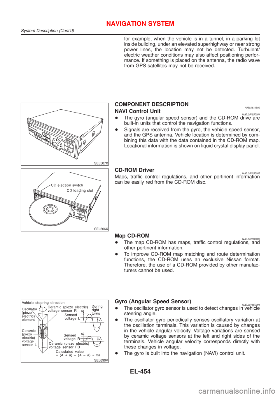
COMPONENT DESCRIPTIONNJEL0516S02NAVI Control UnitNJEL0516S0201+The gyro (angular speed sensor) and the CD-ROM drive are
built-in units that control the navigation functions.
+Signals are received from the gyro, the vehicle speed sensor,
and the GPS antenna. Vehicle location is determined by com-
bining this data with the data contained in the CD-ROM map.
Locational information is shown on liquid crystal display panel.
SEL506X
CD-ROM DriverNJEL0516S0202Maps, traffic control regulations, and other pertinent information
can be easily red from the CD-ROM disc.
Map CD-ROMNJEL0516S0203+The map CD-ROM has maps, traffic control regulations, and
other pertinent information.
+To improve CD-ROM map matching and route determination
functions, the CD-ROM uses an exclusive Nissan format.
Therefore, the use of a CD-ROM provided by other manufac-
turers cannot be used.
SEL690V
Gyro (Angular Speed Sensor)NJEL0516S0204+The oscillator gyro sensor is used to detect changes in vehicle
steering angle.
+The oscillator gyro periodically senses oscillatory variation at
the oscillation terminals. This variation is caused by changes
in the vehicle angular velocity. Voltage variations are sensed
by ceramic voltage sensors at the left and right sides of the
terminals. Vehicle angular velocity corresponds directly with
these changes in voltage.
+The gyro is built into the navigation (NAVI) control unit.
NAVIGATION SYSTEM
System Description (Cont'd)
EL-454
Page 2013 of 2898
MAP DISPLAY
BIRDVIEW
R
SEL524X
BIRDVIEWTNJEL0516S0205The BIRDVIEWTprovides a detailed and easily seen display of
road conditions covering the vehicle's immediate to distant area.
SEL691V
DescriptionNJEL0516S0206+Display area: Trapezoidal representation showing approximate
distances (Wn, D, and Wd).
+Ten horizontal grid lines indicate display width while six verti-
cal grid lines indicate display depth and direction.
+Drawing line area shows open space, depth, and immediate
front area. Each area is to a scale of approximately 5:6:25.
+Pushing the ªZOOM INº button during operation displays the
scale change and the view point height on the left side of the
screen.
The height of the view point increases or decreases when
ªZOOMº or ªWIDEº is selected with the joystick.
NAVIGATION SYSTEM
System Description (Cont'd)
EL-455
Page 2014 of 2898
MAP DISPLAY=NJEL0516S03
SEL525X
Function of each icon is as follows:
1) Azimuth indication
2) Position marker
The tip of the arrow shows the current position. The shaft of
the arrow indicates the direction in which the vehicle is travel-
ing.
3) GPS reception signal (indicates current reception conditions)
4) Distance display (shows the distance in a reduced scale)
NAVIGATION SYSTEM
System Description (Cont'd)
EL-456
Page 2015 of 2898
FUNCTION OF PANEL SWITCH=NJEL0516S04Display with Pushed ªDESTº SwitchNJEL0516S0401
SEL615X
The function of each icon is as follows:
Icon Description
Address Book Favorite areas can be saved to memory.
Address (City/Street) The information can be searched from the address.
Point of Interest (POI) The information of favorite areas can be searched.
Previous Dest.The previous ten destinations stored in memory are
displayed.
City Centre The information can be searched from city name.
Map The information can be searched from the map.
CountryWhen two or more countries are included in a map
CD-ROM, the destination can be searched for under
the country name.
NAVIGATION SYSTEM
System Description (Cont'd)
EL-457
Page 2016 of 2898

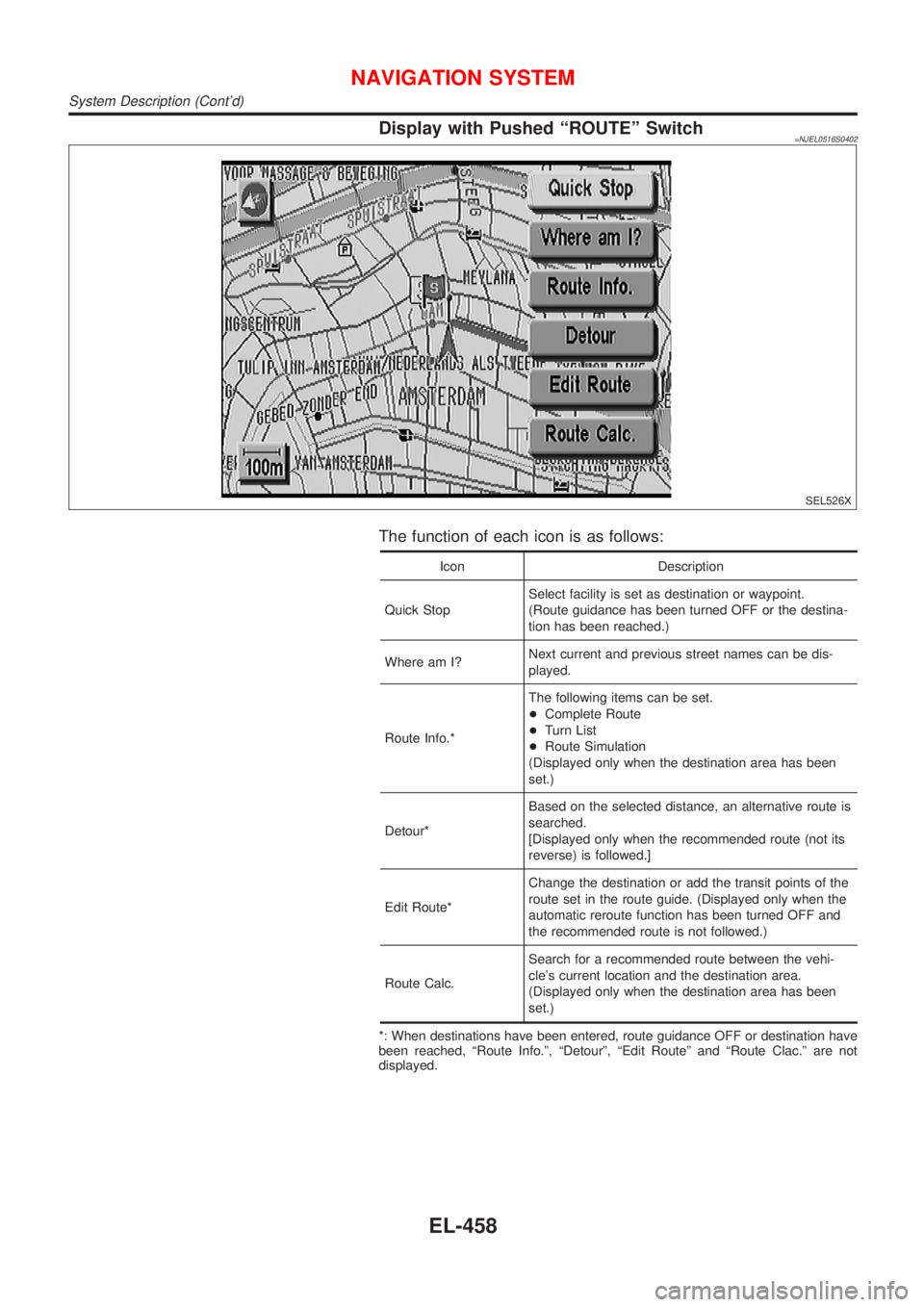
Display with Pushed ªROUTEº Switch=NJEL0516S0402
SEL526X
The function of each icon is as follows:
Icon Description
Quick StopSelect facility is set as destination or waypoint.
(Route guidance has been turned OFF or the destina-
tion has been reached.)
Where am I?Next current and previous street names can be dis-
played.
Route Info.*The following items can be set.
+Complete Route
+Turn List
+Route Simulation
(Displayed only when the destination area has been
set.)
Detour*Based on the selected distance, an alternative route is
searched.
[Displayed only when the recommended route (not its
reverse) is followed.]
Edit Route*Change the destination or add the transit points of the
route set in the route guide. (Displayed only when the
automatic reroute function has been turned OFF and
the recommended route is not followed.)
Route Calc.Search for a recommended route between the vehi-
cle's current location and the destination area.
(Displayed only when the destination area has been
set.)
*: When destinations have been entered, route guidance OFF or destination have
been reached, ªRoute Info.º, ªDetourº, ªEdit Routeº and ªRoute Clac.º are not
displayed.
NAVIGATION SYSTEM
System Description (Cont'd)
EL-458
Page 2017 of 2898
Display with Pushed ªSETTINGº Switch=NJEL0516S0403
SEL614X
The function of each icon is as follows:
Icon Description
Save Current LocationThe current location can be stored in the Address
Book.
System SettingMany adjustments and settings can be made for maxi-
mum driving pleasure and convenience.
Edit Address Book The Address Book data can be edited.
Guidance VolumeThe volume and/or on/off of voice prompt can be con-
trolled by the joystick.
NAVIGATION SYSTEM
System Description (Cont'd)
EL-459
Page 2018 of 2898
Schematic/SedanNJEL0517
HEL424B
NAVIGATION SYSTEM
Schematic/Sedan
EL-460
Page 2019 of 2898
Wiring Diagram Ð NAVI Ð/SedanNJEL0518LHD MODELSNJEL0518S01
HEL425B
NAVIGATION SYSTEM
Wiring Diagram Ð NAVI Ð/Sedan
EL-461