Page 645 of 2898
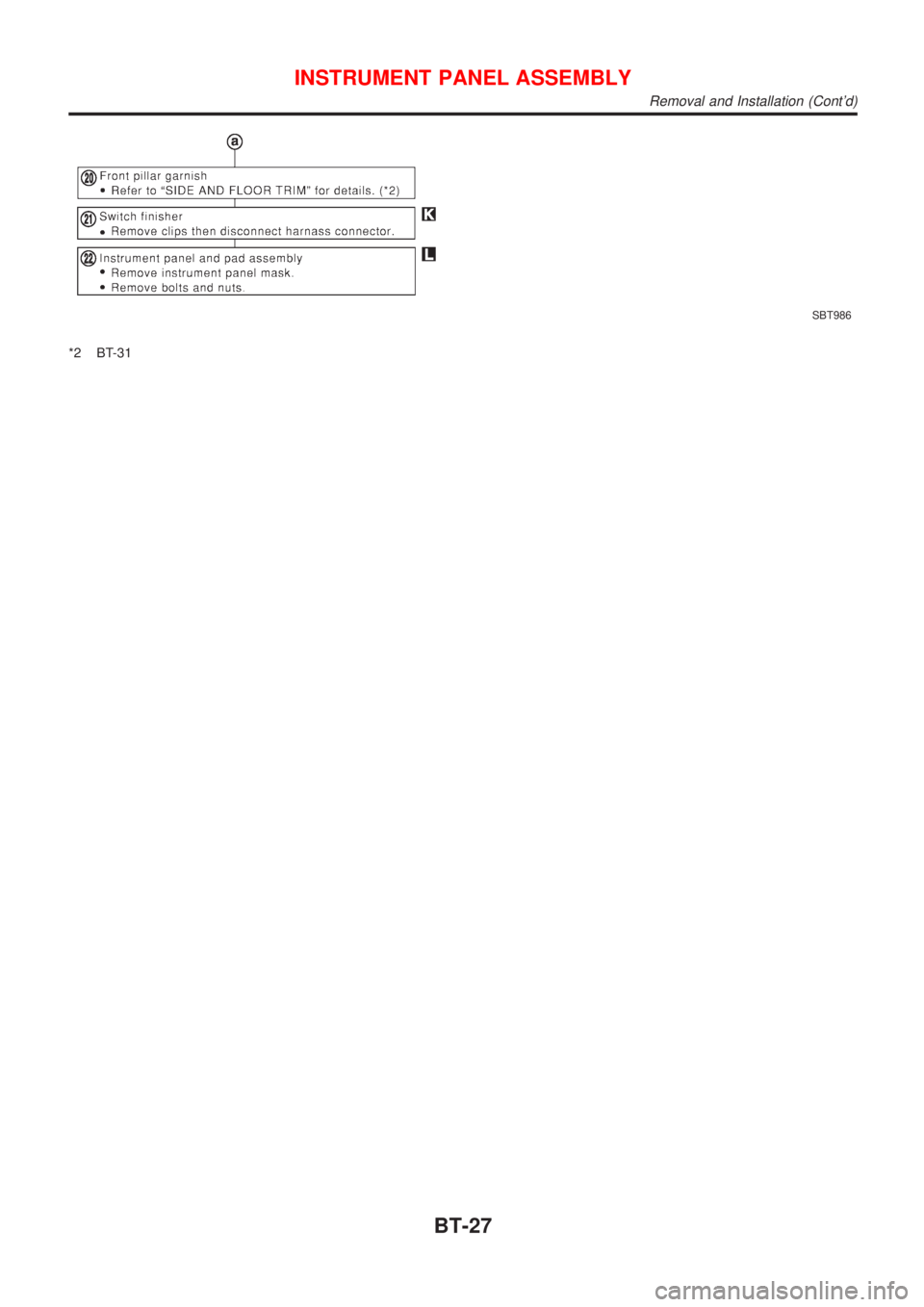
SBT986
*2 BT-31
INSTRUMENT PANEL ASSEMBLY
Removal and Installation (Cont'd)
BT-27
Page 646 of 2898
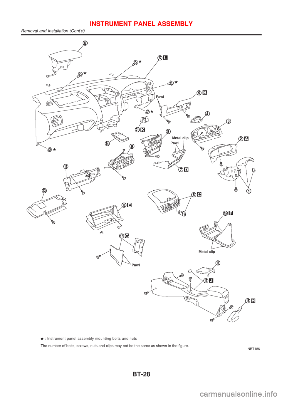
NBT186
INSTRUMENT PANEL ASSEMBLY
Removal and Installation (Cont'd)
BT-28
Page 647 of 2898
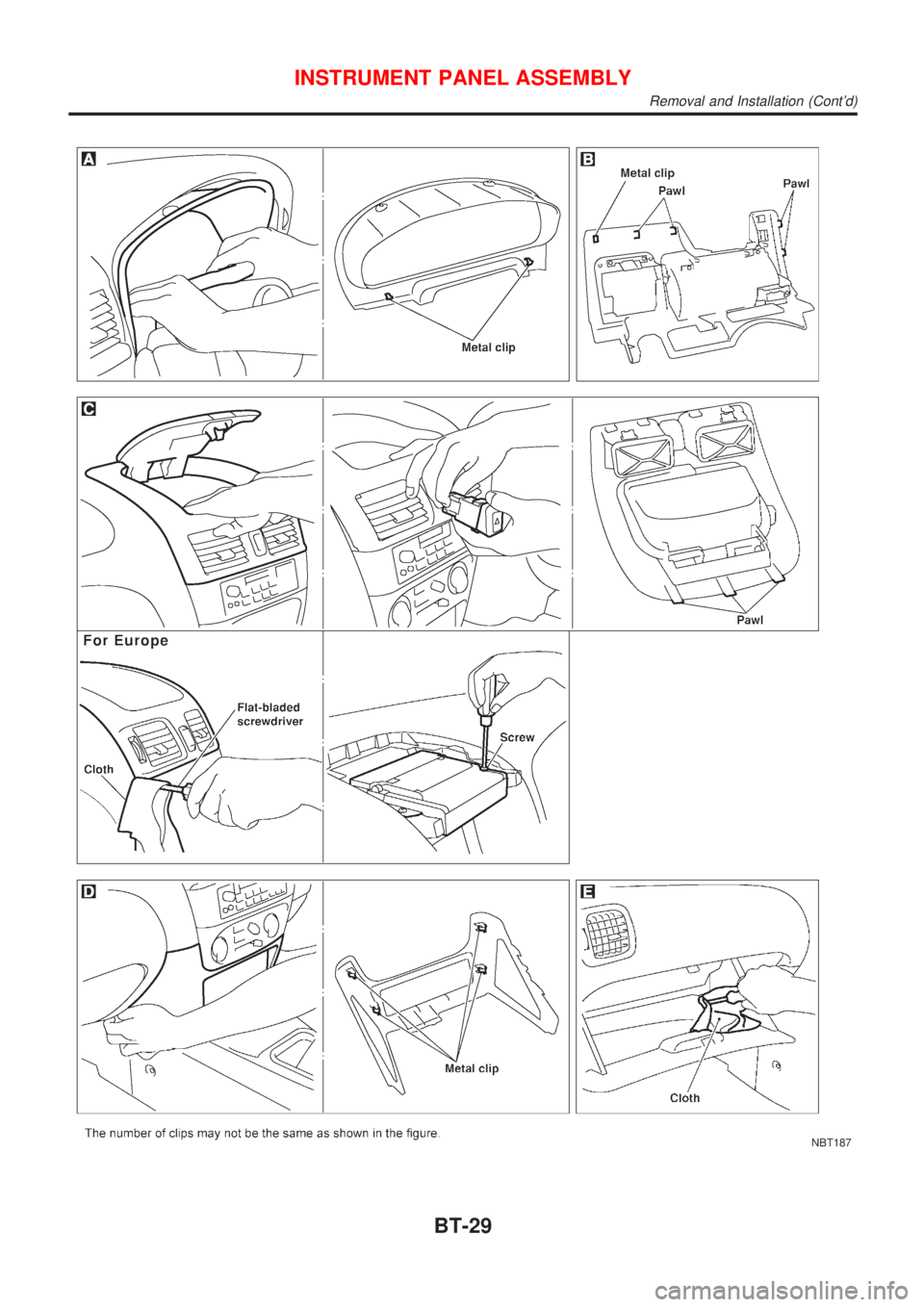
NBT187
INSTRUMENT PANEL ASSEMBLY
Removal and Installation (Cont'd)
BT-29
Page 648 of 2898
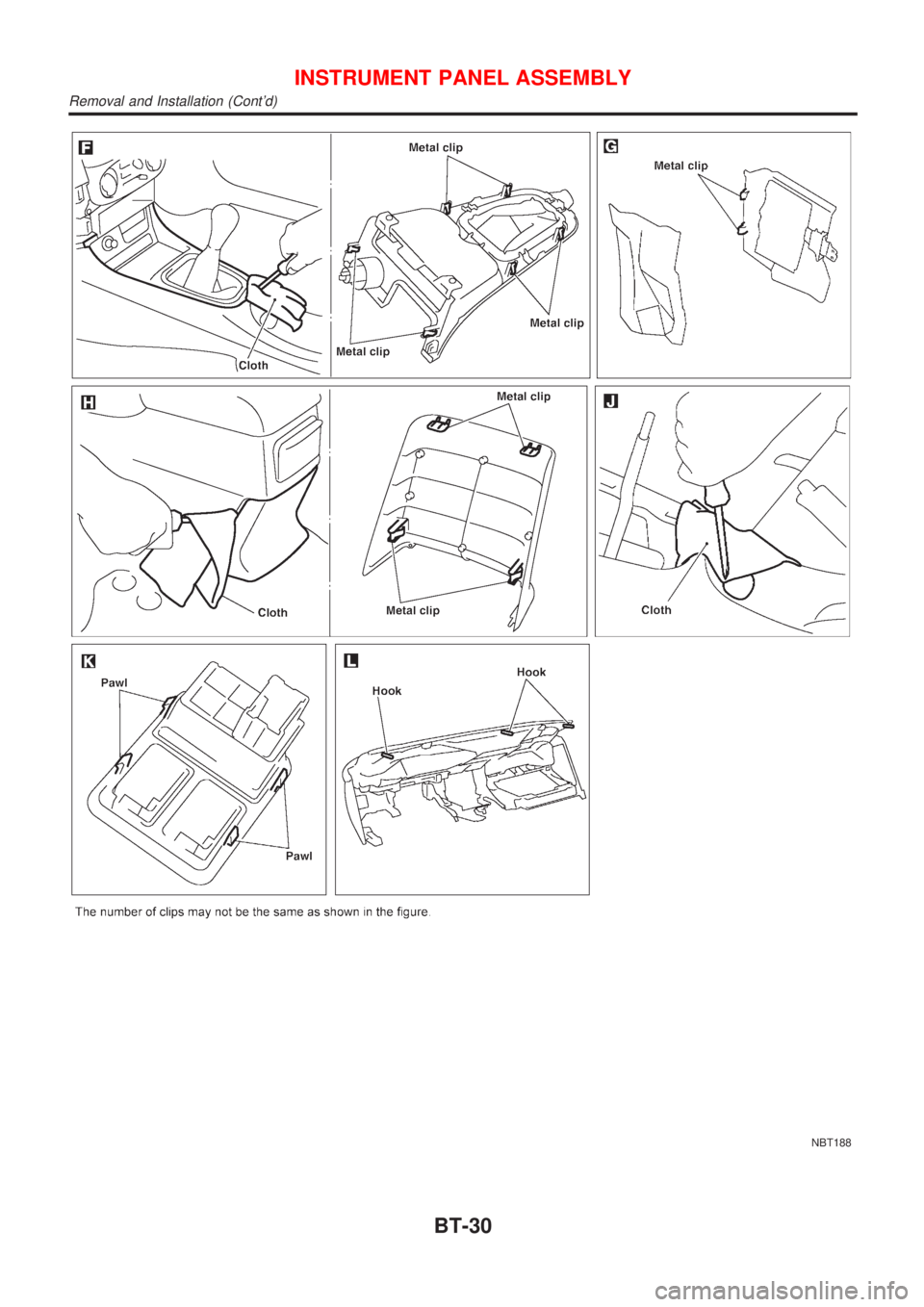
NBT188
INSTRUMENT PANEL ASSEMBLY
Removal and Installation (Cont'd)
BT-30
Page 740 of 2898

Supplemental Restraint System (SRS) ªAIR
BAGº and ªSEAT BELT PRE-TENSIONERº
NJEC0002The Supplemental Restraint System such as ªAIR BAGº and ªSEAT BELT PRE-TENSIONERº used along with
a seat belt, helps to reduce the risk or severity of injury to the driver and front passenger for certain types of
collision. The SRS system composition which is available to NISSAN MODEL N16 is as follows (The compo-
sition varies according to the destination and optional equipment.):
+For a frontal collision
The Supplemental Restraint System consists of driver air bag module (located in the center of the steer-
ing wheel), front passenger air bag module (located on the instrument panel on passenger side), front seat
belt pre-tensioners, a diagnoses sensor unit, warning lamp, wiring harness and spiral cable.
+For a side collision
The Supplemental Restraint System consists of front side air bag module (located in the outer side of front
seat), side air bag (satellite) sensor, diagnoses sensor unit (one of components of air bags for a frontal
collision), wiring harness, warning lamp (one of components of air bags for a frontal collision).
Information necessary to service the system safely is included in theRS sectionof this Service Manual.
WARNING:
+To avoid rendering the SRS inoperative, which could increase the risk of personal injury or death
in the event of a collision which would result in air bag inflation, all maintenance should be per-
formed by an authorized NISSAN dealer.
+Improper maintenance, including incorrect removal and installation of the SRS, can lead to per-
sonal injury caused by unintentional activation of the system. For removal of Spiral Cable and Air
Bag Module, see the RS section.
+Do not use electrical test equipment on any circuit related to the SRS unless instructed to in this
Service Manual. SRS wiring harness can be identified by yellow harness connector.
Precautions for On Board Diagnostic (OBD)
System of Engine and A/T
NJEC0003The ECM has an on board diagnostic system. It will light up the malfunction indicator (MI) to warn the driver
of a malfunction causing emission deterioration.
CAUTION:
+Be sure to turn the ignition switch ªOFFº and disconnect the negative battery terminal before any
repair or inspection work. The open/short circuit of related switches, sensors, solenoid valves, etc.
will cause the MI to light up.
+Be sure to connect and lock the connectors securely after work. A loose (unlocked) connector will
cause the MI to light up due to the open circuit. (Be sure the connector is free from water, grease,
dirt, bent terminals, etc.)
+Certain systems and components, especially those related to OBD, may use a new style slide-
locking type harness connector.
For description and how to disconnect, refer to EL section, ªDescriptionº, ªHARNESS CONNEC-
TORº.
+Be sure to route and secure the harnesses properly after work. The interference of the harness with
a bracket, etc. may cause the MI to light up due to the short circuit.
+Be sure to connect rubber tubes properly after work. A misconnected or disconnected rubber tube
may cause the MI to light up due to the malfunction of fuel injection system, etc.
+Be sure to erase the unnecessary malfunction information (repairs completed) from the ECM and
TCM (Transmission Control Module) before returning the vehicle to the customer.
PRECAUTIONSQG
Supplemental Restraint System (SRS) ªAIR BAGº and ªSEAT BELT PRE-TENSIONERº
EC-16
Page 755 of 2898

System ChartNJEC0013
Input (Sensor) ECM Function Output (Actuator)
+Camshaft position sensor (PHASE)
+Crankshaft position sensor (POS)
+Mass air flow sensor
+Engine coolant temperature sensor
+Heated oxygen sensor 1 (front)
+Ignition switch
+Throttle position sensor
+PNP switch
+Air conditioner switch
+Knock sensor
+EGR temperature sensor*1, *4
+Fuel tank temperature sensor*1, *4
+Battery voltage
+Power steering oil pressure switch
+Vehicle speed sensor
+Intake air temperature sensor
+Heated oxygen sensor 2 (rear)*2
+TCM (Transmission Control Module)*3
+Closed throttle position switch
+Electrical load
+Refrigerant pressure sensorFuel injection & mixture ratio control Injectors
Electronic ignition system Power transistor
Idle air control system IACV-AAC valve
Intake valve timing controlIntake valve timing control sole-
noid valve
Fuel pump control Fuel pump relay
On board diagnostic systemMalfunction indicator
(On the instrument panel)
EGR control*4 EGR volume control valve*4
Heated oxygen sensor 1/2 heater (front/
rear) controlHeated oxygen sensor 1/2 heater
(front/rear)
EVAP canister purge flow controlEVAP canister purge volume con-
trol solenoid valve
Cooling fan control Cooling fan relay
Air conditioning cut control Air conditioner relay
Swirl control valve control*4Swirl control valve control sole-
noid*4
*1: These sensors are not used to control the engine system. They are used only for the on board diagnosis.
*2: Under normal conditions, this sensor is not for engine control operation.
*3: The DTC related to A/T will be sent to ECM.
*4: If so equipped
ENGINE AND EMISSION CONTROL OVERALL SYSTEMQG
System Chart
EC-31
Page 783 of 2898

IntroductionNJEC0029MODELS WITH EURO-OBD SYSTEMNJEC0029S01The ECM has an on board diagnostic system which detects malfunctions related to engine sensors or actua-
tors. The ECM also records various emission-related diagnostic information including:
Diagnostic Trouble Code (DTC) Mode 3 of ISO 15031-5
Freeze Frame data Mode 2 of ISO 15031-5
System Readiness Test (SRT) code Mode 1 of ISO 15031-5
1st Trip Diagnostic Trouble Code (1st Trip DTC) Mode 7 of ISO 15031-5
1st Trip Freeze Frame data
Test values and Test limits Mode 6 of ISO 15031-5
Calibration ID Mode 9 of ISO 15031-5
The above information can be checked using procedures listed in the table below.
X: Applicable Ð: Not applicable
DTC 1st trip DTCFreeze Frame
data1st trip Freeze
Frame dataSRT code Test value
ECM*3 X X*1ÐÐÐÐ
CONSULT-IIXXXXXÐ
GST X X*2 X Ð X X
*1: When DTC and 1st trip DTC simultaneously appear on the display, they cannot be clearly distinguished from each other.
*2: 1st trip DTCs for self-diagnoses concerning SRT items cannot be shown on the GST display.
*3: In diagnostic test mode II (Self-diagnostic results), DTC is displayed on MI. DTC uses a set of four digit numbers. (If so equipped)
The malfunction indicator (MI) on the instrument panel lights up when the same malfunction is detected in two
consecutive trips (Two trip detection logic), or when the ECM enters fail-safe mode. (Refer to EC-154.)
MODELS WITHOUT EURO-OBD SYSTEMNJEC0029S02The ECM has an on board diagnostic system, which detects malfunctions related to engine sensors or actua-
tors. The ECM also records various emission-related diagnostic information including:
Diagnostic Trouble Code (DTC)
Freeze Frame data
1st Trip Diagnostic Trouble Code (1st Trip DTC)
1st Trip Freeze Frame data
The above information can be checked using procedures listed in the table below.
X: Applicable Ð: Not applicable
DTC 1st trip DTC Freeze Frame data1st trip Freeze Frame
data
CONSULT-II X X X X
ECM*1 X X*2 Ð Ð
*1: In diagnostic test mode II (Self-diagnostic results), (1st trip) DTC is displayed on the MI by a set of four digit numbers.
*2: When the DTC and the 1st trip DTC appear on the display simultaneously, it is difficult to clearly distinguish one from the other.
Two Trip Detection LogicNJEC0030MODELS WITH EURO-OBD SYSTEMNJEC0030S01When a malfunction is detected for the first time, 1st trip DTC and 1st trip Freeze Frame data are stored in
the ECM memory. The MI will not light up at this stage <1st trip>.
If the same malfunction is detected again during the next drive, the DTC and Freeze Frame data are stored
in the ECM memory, and the MI lights up. The MI lights up at the same time when the DTC is stored <2nd
trip>.
ON BOARD DIAGNOSTIC SYSTEM DESCRIPTIONQG
Introduction
EC-59
Page 798 of 2898
SEF543X
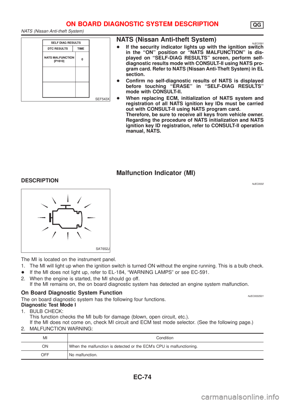
NATS (Nissan Anti-theft System)NJEC0591+If the security indicator lights up with the ignition switch
in the ªONº position or ªNATS MALFUNCTIONº is dis-
played on ªSELF-DIAG RESULTSº screen, perform self-
diagnostic results mode with CONSULT-II using NATS pro-
gram card. Refer to NATS (Nissan Anti-Theft System) in EL
section.
+Confirm no self-diagnostic results of NATS is displayed
before touching ªERASEº in ªSELF-DIAG RESULTSº
mode with CONSULT-II.
+When replacing ECM, initialization of NATS system and
registration of all NATS ignition key IDs must be carried
out with CONSULT-II using NATS program card.
Therefore, be sure to receive all keys from vehicle owner.
Regarding the procedure of NATS initialization and NATS
ignition key ID registration, refer to CONSULT-II operation
manual, NATS.
Malfunction Indicator (MI)
DESCRIPTIONNJEC0032
SAT652J
The MI is located on the instrument panel.
1. The MI will light up when the ignition switch is turned ON without the engine running. This is a bulb check.
+If the MI does not light up, refer to EL-184, ªWARNING LAMPSº or see EC-591.
2. When the engine is started, the MI should go off.
If the MI remains on, the on board diagnostic system has detected an engine system malfunction.
On Board Diagnostic System FunctionNJEC0032S01The on board diagnostic system has the following four functions.
Diagnostic Test Mode I
1. BULB CHECK:
This function checks the MI bulb for damage (blown, open circuit, etc.).
If the MI does not come on, check MI circuit and ECM test mode selector. (See the following page.)
2. MALFUNCTION WARNING:
MI Condition
ON When the malfunction is detected or the ECM's CPU is malfunctioning.
OFF No malfunction.
ON BOARD DIAGNOSTIC SYSTEM DESCRIPTIONQG
NATS (Nissan Anti-theft System)
EC-74