2001 NISSAN ALMERA N16 Air condition
[x] Cancel search: Air conditionPage 426 of 2493

MONITOR ITEM CONDITION SPECIFICATION
COOLING FAN+After warming up engine, idle
the engine.
+Air conditioner switch: OFFEngine coolant temperature is 99ÉC
(210ÉF) or lessOFF
Engine coolant temperature is 100ÉC
(212ÉF) or moreON
HO2S1 HTR (B1)+Engine speed: Below 3,200 rpm ON
+Engine speed: Above 3,200 rpm OFF
HO2S2 HTR (B1)+Engine speedBelow 3,600 rpm [After driving for 2
minutes at a speed of 70 km/h (43
MPH) or more]ON
Above 3,600 rpm OFF
+Ignition switch ON (Engine stopped) OFF
TRVL AFTER MI+Ignition switch: ONVehicle has traveled after MI has
turned ON.0 - 65,535 km
(0 - 40,723 mile)
*: If so equipped
Major Sensor Reference Graph in Data Monitor
Mode
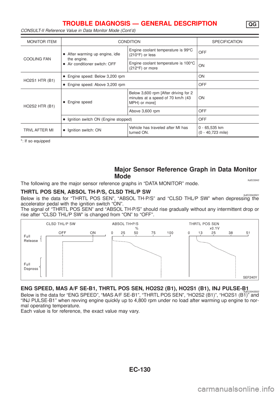
NJEC0043The following are the major sensor reference graphs in ªDATA MONITORº mode.
THRTL POS SEN, ABSOL TH´P/S, CLSD THL/P SWNJEC0043S01Below is the data for ªTHRTL POS SENº, ªABSOL TH´P/Sº and ªCLSD THL/P SWº when depressing the
accelerator pedal with the ignition switch ªONº.
The signal of ªTHRTL POS SENº and ªABSOL TH´P/Sº should rise gradually without any intermittent drop or
rise after ªCLSD THL/P SWº is changed from ªONº to ªOFFº.
SEF240Y
ENG SPEED, MAS A/F SE-B1, THRTL POS SEN, HO2S2 (B1), HO2S1 (B1), INJ PULSE-B1NJEC0043S02Below is the data for ªENG SPEEDº, ªMAS A/F SE-B1º, ªTHRTL POS SENº, ªHO2S2 (B1)º, ªHO2S1 (B1)º and
ªINJ PULSE-B1º when revving engine quickly up to 4,800 rpm under no load after warming up engine to nor-
mal operating temperature.
Each value is for reference, the exact value may vary.
TROUBLE DIAGNOSIS Ð GENERAL DESCRIPTIONQG
CONSULT-II Reference Value in Data Monitor Mode (Cont'd)
EC-130
Page 430 of 2493
![NISSAN ALMERA N16 2001 Electronic Repair Manual TERMI-
NAL
NO.WIRE
COLORITEM CONDITION DATA (DC Voltage)
3 W/RHeated oxygen sensor 2
heater (rear)[Engine is running]
+Engine speed is below 3,600 rpm
+After driving for 2 minutes at a speed of 70
km/ NISSAN ALMERA N16 2001 Electronic Repair Manual TERMI-
NAL
NO.WIRE
COLORITEM CONDITION DATA (DC Voltage)
3 W/RHeated oxygen sensor 2
heater (rear)[Engine is running]
+Engine speed is below 3,600 rpm
+After driving for 2 minutes at a speed of 70
km/](/manual-img/5/57351/w960_57351-429.png)
TERMI-
NAL
NO.WIRE
COLORITEM CONDITION DATA (DC Voltage)
3 W/RHeated oxygen sensor 2
heater (rear)[Engine is running]
+Engine speed is below 3,600 rpm
+After driving for 2 minutes at a speed of 70
km/h (43 MPH) or moreApproximately 0.7V
[Ignition switch ªONº]
+Engine stopped
+Engine speed is above 3,600 rpmBATTERY VOLTAGE
(11 - 14V)
4 R/BHeated oxygen sensor 1
heater (front)[Engine is running]
+Engine speed is below 3,200 rpmApproximately 0V
[Engine is running]
+Engine speed is above 3,200 rpmBATTERY VOLTAGE
(11 - 14V)
6
7
15
16BR
L/G
P
ORIACV-AAC valve[Engine is running]
+Warm-up condition
+Idle speed0.1 - 14V
8*
9*
17*
18*SB
W/B
R/Y
BR/REGR volume control
valve[Engine is running]
+Warm-up condition
+Rev engine from 2,000 to 4,000 rpm0 - 14V
10 Y/B A/T signal No. 3[Engine is running]
+Idle speedApproximately 0V
13 LG/R Cooling fan relay[Engine is running]
+Cooling fan is not operatingBATTERY VOLTAGE
(11 - 14V)
[Engine is running]
+Cooling fan is operatingApproximately 0V
14 GY/LEVAP canister purge
volume control valve
(ON/OFF duty)[Engine is running]
+Warm-up condition
+Accelerator pedal depressed5 - 12V
SEF975W
19 BR/W A/T signal No. 5[Engine is running]
+Idle speedApproximately 8V
21 B/P Fuel pump relay[Ignition switch ªONº]
+For 1 second after turning ignition switch
ªONº
[Engine is running]0-1V
[Ignition switch ªONº]
+More than 1 second after turning ignition
switch ªONºBATTERY VOLTAGE
(11 - 14V)
22 OR/L Malfunction indicator[Ignition switch ªONº]0-1V
[Engine is running]
+Idle speedBATTERY VOLTAGE
(11 - 14V)
23 L Air conditioner relay[Engine is running]
+Both A/C switch and blower switch are ªONºApproximately 0V
[Engine is running]
+A/C switch is ªOFFºBATTERY VOLTAGE
(11 - 14V)
TROUBLE DIAGNOSIS Ð GENERAL DESCRIPTIONQG
ECM Terminals and Reference Value (Cont'd)
EC-134
Page 432 of 2493
![NISSAN ALMERA N16 2001 Electronic Repair Manual TERMI-
NAL
NO.WIRE
COLORITEM CONDITION DATA (DC Voltage)
42 G/OR PNP switch[Ignition switch ªONº]
+Gear position is ªNeutral positionº (M/T mod-
els)
+Gear position is ªPº or ªNº (A/T models)A NISSAN ALMERA N16 2001 Electronic Repair Manual TERMI-
NAL
NO.WIRE
COLORITEM CONDITION DATA (DC Voltage)
42 G/OR PNP switch[Ignition switch ªONº]
+Gear position is ªNeutral positionº (M/T mod-
els)
+Gear position is ªPº or ªNº (A/T models)A](/manual-img/5/57351/w960_57351-431.png)
TERMI-
NAL
NO.WIRE
COLORITEM CONDITION DATA (DC Voltage)
42 G/OR PNP switch[Ignition switch ªONº]
+Gear position is ªNeutral positionº (M/T mod-
els)
+Gear position is ªPº or ªNº (A/T models)Approximately 0V
[Ignition switch ªONº]
+Except the above gear positionA/T models
BATTERY VOLTAGE
(11 - 14V)
M/T models
Approximately 5V
43 B/R Ignition switch[Ignition switch ªOFFº]0V
[Ignition switch ªONº]BATTERY VOLTAGE
(11 - 14V)
44 L/R Air conditioner switch[Engine is running]
+Both air conditioner switch and blower switch
are ªONº (Compressor operates)Approximately 0V
[Engine is running]
+Air conditioner switch is ªOFFºApproximately 5V
46 PU/WPower steering oil pres-
sure switch[Engine is running]
+Steering wheel is fully turnedApproximately 0V
[Engine is running]
+Steering wheel is not turnedApproximately 5V
48 B ECM ground[Engine is running]
+Idle speedEngine ground
50 L/BElectrical load signal
(Headlamp and
Rear defogger)[Engine is running]
+Headlamp switch or rear defogger switch is
ªONºBATTERY VOLTAGE
(11 - 14V)
[Engine is running]
+Headlamp switch and rear defogger switch
are ªOFFºApproximately 0V
51 LG/B Blower fan SW[Ignition switch ªONº]
+Blower fan switch is ªONºApproximately 0V
[Ignition switch ªONº]
+Blower fan switch is ªOFFºApproximately 5V
54 Y/R A/T signal No. 1[Engine is running]
+Idle speedApproximately 0V
55 Y/G A/T signal No. 2[Engine is running]
+Idle speedApproximately 0V
56 G/Y A/T signal No. 4[Engine is running]
+Idle speedApproximately 0V
57 B ECM ground[Engine is running]
+Idle speedEngine ground
58 B Sensors' ground[Engine is running]
+Warm-up condition
+Idle speedApproximately 0V
TROUBLE DIAGNOSIS Ð GENERAL DESCRIPTIONQG
ECM Terminals and Reference Value (Cont'd)
EC-136
Page 433 of 2493
![NISSAN ALMERA N16 2001 Electronic Repair Manual TERMI-
NAL
NO.WIRE
COLORITEM CONDITION DATA (DC Voltage)
61 G Mass air flow sensor[Engine is running]
+Warm-up condition
+Idle speed1.0 - 1.7V
[Engine is running]
+Warm-up condition
+Engine speed is 2 NISSAN ALMERA N16 2001 Electronic Repair Manual TERMI-
NAL
NO.WIRE
COLORITEM CONDITION DATA (DC Voltage)
61 G Mass air flow sensor[Engine is running]
+Warm-up condition
+Idle speed1.0 - 1.7V
[Engine is running]
+Warm-up condition
+Engine speed is 2](/manual-img/5/57351/w960_57351-432.png)
TERMI-
NAL
NO.WIRE
COLORITEM CONDITION DATA (DC Voltage)
61 G Mass air flow sensor[Engine is running]
+Warm-up condition
+Idle speed1.0 - 1.7V
[Engine is running]
+Warm-up condition
+Engine speed is 2,500 rpm1.5 - 2.1V
62 WHeated oxygen sensor 1
(front)[Engine is running]
+Warm-up condition
+Engine speed is 2,000 rpm0 - Approximately 0.7V
SEF008W
63 LHeated oxygen sensor 2
(rear)[Engine is running]
+After warming up to normal operating tem-
perature and engine speed is 3,000 rpm0 - Approximately 1.0V
64 Y/BIntake air temperature
sensor[Engine is running]Approximately 0 - 4.8V
Output voltage varies with
intake air temperature
66
75R
RCamshaft position sen-
sor (PHASE)[Engine is running]
+Warm-up condition
+Idle speed2.0 - 3.0V
SEF977W
[Engine is running]
+Engine speed is 2,000 rpm2.0 - 3.0V
SEF978W
67 W/LPower supply for ECM
(Back-up)[Ignition switch ªOFFº]BATTERY VOLTAGE
(11 - 14V)
70 BR/WEngine coolant tempera-
ture sensor[Engine is running]Approximately 0 - 4.8V
Output voltage varies with
engine coolant temperature
71 GYThrottle position sensor
signal output[Engine is running]
+Warm-up condition
+Accelerator pedal fully releasedApproximately 0.4V
[Ignition switch ªONº]
+Accelerator pedal fully depressedApproximately 4V
TROUBLE DIAGNOSIS Ð GENERAL DESCRIPTIONQG
ECM Terminals and Reference Value (Cont'd)
EC-137
Page 434 of 2493
![NISSAN ALMERA N16 2001 Electronic Repair Manual TERMI-
NAL
NO.WIRE
COLORITEM CONDITION DATA (DC Voltage)
72* P/B EGR temperature sensor[Engine is running]
+Warm-up condition
+Idle speedLess than 4.5V
[Engine is running]
+Warm-up condition
+EGR syst NISSAN ALMERA N16 2001 Electronic Repair Manual TERMI-
NAL
NO.WIRE
COLORITEM CONDITION DATA (DC Voltage)
72* P/B EGR temperature sensor[Engine is running]
+Warm-up condition
+Idle speedLess than 4.5V
[Engine is running]
+Warm-up condition
+EGR syst](/manual-img/5/57351/w960_57351-433.png)
TERMI-
NAL
NO.WIRE
COLORITEM CONDITION DATA (DC Voltage)
72* P/B EGR temperature sensor[Engine is running]
+Warm-up condition
+Idle speedLess than 4.5V
[Engine is running]
+Warm-up condition
+EGR system is operating0 - 1.0V
73 BMass air flow sensor
ground[Engine is running]
+Warm-up condition
+Idle speedApproximately 0V
74 R/LRefrigerant pressure
sensor[Engine is running]
+Air conditioner switch is ªONº
(Compressor operates)1.0 - 4.0V
[Engine is running]
+Warm-up condition
+Idle speed
+Air conditioner switch is turned from ªONº to
ªOFFºVoltage is gradually decreasing.
81 W Knock sensor[Engine is running]
+Idle speed1.0 - 4.0V
85 RCrankshaft position sen-
sor (POS)[Engine is running]
+Warm-up condition
+Idle speed3.0 - 4.0V
SEF979W
[Engine is running]
+Engine speed is 2,000 rpm3.0 - 4.0V
SEF980W
86 PU/R Vehicle speed sensor[Engine is running]
+Lift up the vehicle
+Vehicle speed is 40 km/h (25 MPH)2.5-3V
SEF976W
91 PU A/T check signal[Engine is running]
+Idle speed0 - Approximately 5V
92 Y Throttle position sensor[Engine is running]
+Accelerator pedal released0.15 - 0.85V
[Ignition switch ªONº]
+Accelerator pedal fully depressed3.5 - 4.7V
TROUBLE DIAGNOSIS Ð GENERAL DESCRIPTIONQG
ECM Terminals and Reference Value (Cont'd)
EC-138
Page 436 of 2493

DescriptionNJEC1265The specification (SP) value indicates the tolerance of the value that is displayed in ªDATA MONITOR (SPEC)º
mode of CONSULT-II during normal operation of the Engine Control System. When the value in ªDATA MONI-
TOR (SPEC)º mode is within the SP value, the Engine Control System is confirmed OK. When the value in
ªDATA MONITOR (SPEC)º mode is NOT within the SP value, the Engine Control System may have one or
more malfunctions.
The SP value is used to detect malfunctions that may affect the Engine Control System, but will not light the
MIL.
The SP value will be displayed for the following three items:
+B/FUEL SCHDL (The fuel injection pulse width programmed into ECM prior to any learned on board cor-
rection)
+A/F ALPHA-B1 (The mean value of air-fuel ratio feedback correction factor per cycle)
+MAS A/F SE-B1 (The signal voltage of the mass air flow sensor)
Testing ConditionNJEC1266+Vehicle driven distance: More than 5,000 km (3,017 miles)
+Barometric pressure: 98.3 - 104.3 kPa (0.983 - 1.043 bar, 1.003 - 1.064 kg/cm2, 14.25 - 15.12 psi)
+Atmospheric temperature: 20 - 30ÉC (68 - 86ÉF)
+Engine coolant temperature: 75 - 95ÉC (167 - 203ÉF)
+Transmission: Warmed-up*1
+Electrical load: Not applied*2
+Engine speed: Idle
*1: For A/T or CVT models, after the engine is warmed up to normal operating temperature, drive vehicle until
ªFLUID TEMP SEº (A/T or CVT fluid temperature sensor signal) indicates less than 0.9V. For M/T models, drive
vehicle for 5 minutes after the engine is warmed up to normal operating temperature.
*2: Rear window defogger switch, air conditioner switch, lighting switch are ªOFFº. Cooling fans are not oper-
ating. Steering wheel is straight ahead.
SEF601Z
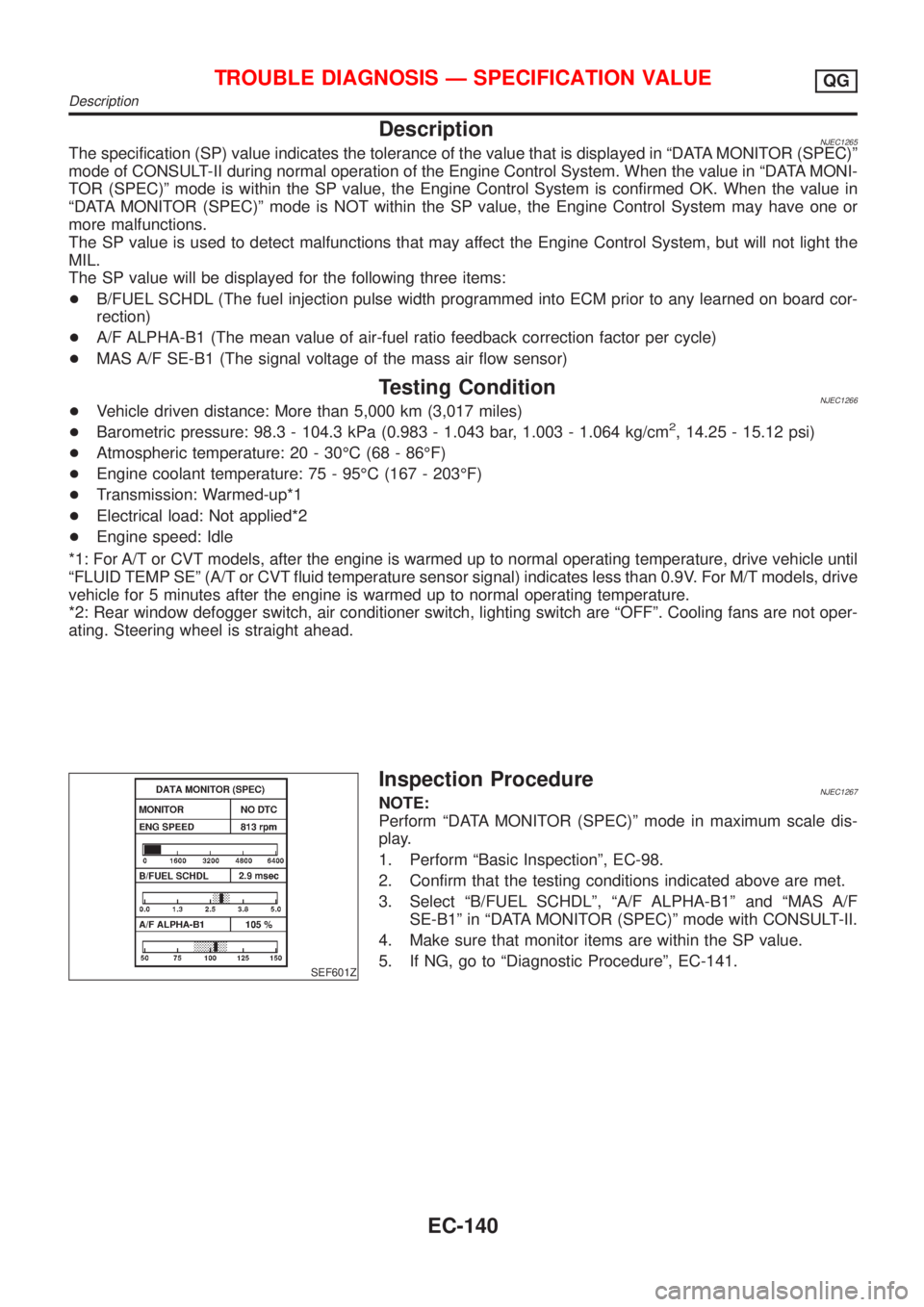
Inspection ProcedureNJEC1267NOTE:
Perform ªDATA MONITOR (SPEC)º mode in maximum scale dis-
play.
1. Perform ªBasic Inspectionº, EC-98.
2. Confirm that the testing conditions indicated above are met.
3. Select ªB/FUEL SCHDLº, ªA/F ALPHA-B1º and ªMAS A/F
SE-B1º in ªDATA MONITOR (SPEC)º mode with CONSULT-II.
4. Make sure that monitor items are within the SP value.
5. If NG, go to ªDiagnostic Procedureº, EC-141.
TROUBLE DIAGNOSIS Ð SPECIFICATION VALUEQG
Description
EC-140
Page 440 of 2493

DescriptionNJEC0045Intermittent incidents (I/I) may occur. In many cases, the problem resolves itself (the part or circuit function
returns to normal without intervention). It is important to realize that the symptoms described in the custom-
er's complaint often do not recur on DTC (1st trip) visits. Realize also that the most frequent cause of I/I
occurrences is poor electrical connections. Because of this, the conditions under which the incident occurred
may not be clear. Therefore, circuit checks made as part of the standard diagnostic procedure may not indi-
cate the specific problem area.
COMMON I/I REPORT SITUATIONSNJEC0045S01
STEP in Work Flow Situation
IIThe CONSULT-II is used. The SELF-DIAG RESULTS screen shows time data other than ª0º or
ª1tº.
III The symptom described by the customer does not recur.
IV (1st trip) DTC data does not appear during the DTC Confirmation Procedure.
VI The Diagnostic Procedure for PXXXX does not indicate the problem area.
Diagnostic ProcedureNJEC0046
1 INSPECTION START
Erase (1st trip) DTCs. Refer to ªHow to Erase Emission-related Diagnostic Informationº, EC-68, EC-71.
©GO TO 2.
2 CHECK GROUND TERMINALS
Check ground terminals for corroding or loose connection. Refer to GI-27, ªGROUND INSPECTIONº.
OK or NG
OK©GO TO 3.
NG©Repair or replace.
3 SEARCH FOR ELECTRICAL INCIDENT
Perform GI-22, ªIncident Simulation Testsº.
OK or NG
OK©INSPECTION END
NG©Repair or replace.
TROUBLE DIAGNOSIS FOR INTERMITTENT INCIDENTQG
Description
EC-144
Page 448 of 2493

SEF987W
Component DescriptionNJEC0050The mass air flow sensor is placed in the stream of intake air. It
measures the intake flow rate by measuring a part of the entire
intake flow. It consists of a hot wire that is supplied with electric
current from the ECM. The temperature of the hot wire is controlled
by the ECM a certain amount. The heat generated by the hot wire
is reduced as the intake air flows around it. The more air, the
greater the heat loss.
Therefore, the ECM must supply more electric current to maintain
the temperature of the hot wire as air flow increases. The ECM
detects the air flow by means of this current change.
CONSULT-II Reference Value in Data Monitor
Mode
NJEC0051Specification data are reference values.
MONITOR ITEM CONDITION SPECIFICATION
MAS A/F SE-B1+Engine: After warming up
+Air conditioner switch: ªOFFº
+Shift lever: ªNº
+No-loadIdle 1.0 - 1.7V
2,500 rpm 1.5 - 2.1V
MASS AIRFLOW+Engine: After warming up
+Air conditioner switch: ªOFFº
+Shift lever: ªNº
+No-loadIdle 1.0 - 4.0 g´m/s
2,500 rpm 5.0 - 10.0 g´m/s
ECM Terminals and Reference ValueNJEC0052Specification data are reference values and are measured between each terminal and ground.
CAUTION:
Do not use ECM ground terminals when measuring input/output voltage. Doing so may result in dam-
age to the ECM's transistor. Use a ground other than ECM terminals, such as the ground.
TER-
MINAL
NO.WIRE
COLORITEM CONDITION DATA (DC Voltage)
61 G Mass air flow sensor[Engine is running]
+Warm-up condition
+Idle speed1.0 - 1.7V
[Engine is running]
+Warm-up condition
+Engine speed is 2,500 rpm1.5 - 2.1V
73 BMass air flow sensor
ground[Engine is running]
+Warm-up condition
+Idle speedApproximately 0V
On Board Diagnosis LogicNJEC0053
DTC No. Malfunction is detected when ... Check Items (Possible Cause)
P0100
0100A) An excessively high voltage from the sensor is sent
to ECM when engine is not running.+Harness or connectors
(The sensor circuit is open or shorted.)
+Mass air flow sensor
B) An excessively low voltage from the sensor is sent
to ECM* when engine is running.+Harness or connectors
(The sensor circuit is open or shorted.)
+Intake air leaks
+Mass air flow sensor
*: When this malfunction is detected, the ECM enters fail-safe mode and the MI lights up.
DTC P0100 MASS AIR FLOW SENSOR (MAFS)QG
Component Description
EC-152