2001 NISSAN ALMERA N16 Air condition
[x] Cancel search: Air conditionPage 581 of 2493
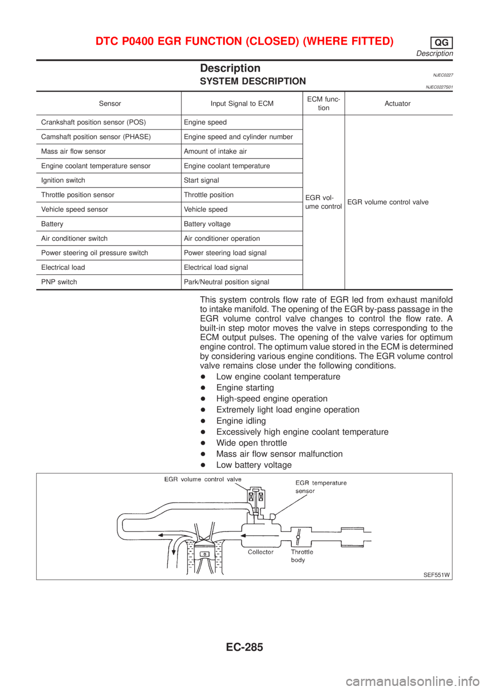
DescriptionNJEC0227SYSTEM DESCRIPTIONNJEC0227S01
Sensor Input Signal to ECMECM func-
tionActuator
Crankshaft position sensor (POS) Engine speed
EGR vol-
ume controlEGR volume control valve Camshaft position sensor (PHASE) Engine speed and cylinder number
Mass air flow sensor Amount of intake air
Engine coolant temperature sensor Engine coolant temperature
Ignition switch Start signal
Throttle position sensor Throttle position
Vehicle speed sensor Vehicle speed
Battery Battery voltage
Air conditioner switch Air conditioner operation
Power steering oil pressure switch Power steering load signal
Electrical load Electrical load signal
PNP switch Park/Neutral position signal
This system controls flow rate of EGR led from exhaust manifold
to intake manifold. The opening of the EGR by-pass passage in the
EGR volume control valve changes to control the flow rate. A
built-in step motor moves the valve in steps corresponding to the
ECM output pulses. The opening of the valve varies for optimum
engine control. The optimum value stored in the ECM is determined
by considering various engine conditions. The EGR volume control
valve remains close under the following conditions.
+Low engine coolant temperature
+Engine starting
+High-speed engine operation
+Extremely light load engine operation
+Engine idling
+Excessively high engine coolant temperature
+Wide open throttle
+Mass air flow sensor malfunction
+Low battery voltage
SEF551W
DTC P0400 EGR FUNCTION (CLOSED) (WHERE FITTED)QG
Description
EC-285
Page 582 of 2493
SEF552W
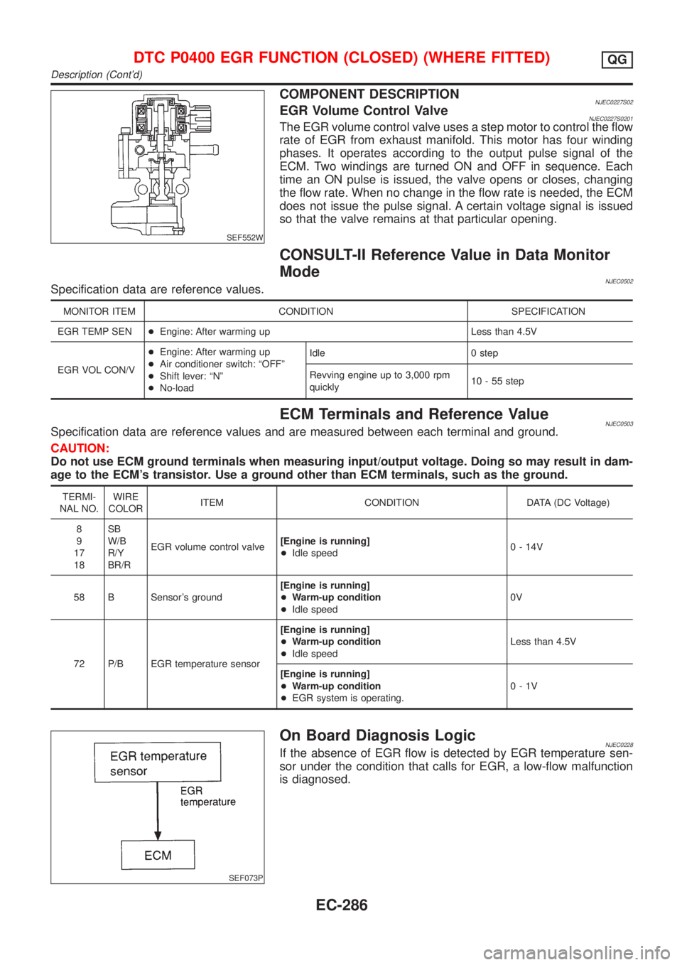
COMPONENT DESCRIPTIONNJEC0227S02EGR Volume Control ValveNJEC0227S0201The EGR volume control valve uses a step motor to control the flow
rate of EGR from exhaust manifold. This motor has four winding
phases. It operates according to the output pulse signal of the
ECM. Two windings are turned ON and OFF in sequence. Each
time an ON pulse is issued, the valve opens or closes, changing
the flow rate. When no change in the flow rate is needed, the ECM
does not issue the pulse signal. A certain voltage signal is issued
so that the valve remains at that particular opening.
CONSULT-II Reference Value in Data Monitor
Mode
NJEC0502Specification data are reference values.
MONITOR ITEM CONDITION SPECIFICATION
EGR TEMP SEN+Engine: After warming up Less than 4.5V
EGR VOL CON/V+Engine: After warming up
+Air conditioner switch: ªOFFº
+Shift lever: ªNº
+No-loadIdle 0 step
Revving engine up to 3,000 rpm
quickly10 - 55 step
ECM Terminals and Reference ValueNJEC0503Specification data are reference values and are measured between each terminal and ground.
CAUTION:
Do not use ECM ground terminals when measuring input/output voltage. Doing so may result in dam-
age to the ECM's transistor. Use a ground other than ECM terminals, such as the ground.
TERMI-
NAL NO.WIRE
COLORITEM CONDITION DATA (DC Voltage)
8
9
17
18SB
W/B
R/Y
BR/REGR volume control valve[Engine is running]
+Idle speed0 - 14V
58 B Sensor's ground[Engine is running]
+Warm-up condition
+Idle speed0V
72 P/B EGR temperature sensor[Engine is running]
+Warm-up condition
+Idle speedLess than 4.5V
[Engine is running]
+Warm-up condition
+EGR system is operating.0-1V
SEF073P
On Board Diagnosis LogicNJEC0228If the absence of EGR flow is detected by EGR temperature sen-
sor under the condition that calls for EGR, a low-flow malfunction
is diagnosed.
DTC P0400 EGR FUNCTION (CLOSED) (WHERE FITTED)QG
Description (Cont'd)
EC-286
Page 583 of 2493
DTC No. Malfunction is detected when ... Check Items (Possible Cause)
P0400
0400+No EGR flow is detected under conditions that call for
EGR.+Harness or connectors
(EGR volume control valve circuit is open or
shorted.)
+EGR volume control valve stuck closed
+Dead (Weak) battery
+EGR passage clogged
+EGR temperature sensor and circuit
+Exhaust gas leaks
SEF013Y
SEF845Y
SEF846Y
SEF235Y
DTC Confirmation ProcedureNJEC0229CAUTION:
Always drive vehicle at a safe speed.
NOTE:
+If ªDTC Confirmation Procedureº has been previously
conducted, always turn ignition switch ªOFFº and wait at least
9 seconds before conducting the next test.
+P0400 will not be displayed at ªSELF-DIAG RESULTSº mode
with CONSULT-II even though DTC work support test result is
ªNGº.
TESTING CONDITION:
+Before performing the following procedure, confirm bat-
tery voltage is more than 10V at idle, then stop engine
immediately.
+For best result, perform the test at a temperature of 0ÉC
(32ÉF) or higher.
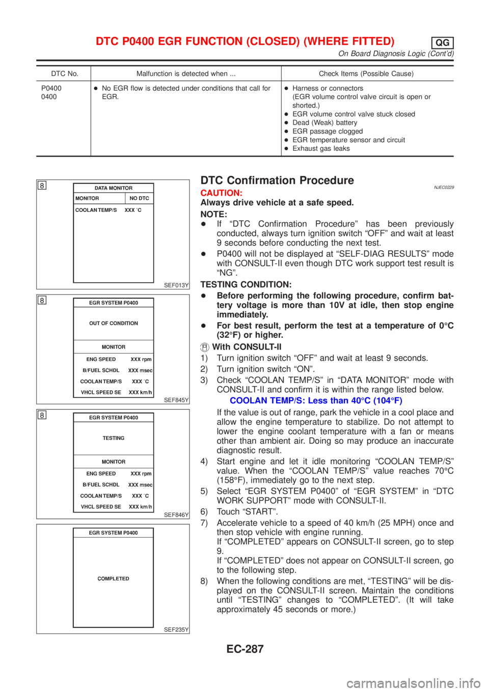
With CONSULT-II
1) Turn ignition switch ªOFFº and wait at least 9 seconds.
2) Turn ignition switch ªONº.
3) Check ªCOOLAN TEMP/Sº in ªDATA MONITORº mode with
CONSULT-II and confirm it is within the range listed below.
COOLAN TEMP/S: Less than 40ÉC (104ÉF)
If the value is out of range, park the vehicle in a cool place and
allow the engine temperature to stabilize. Do not attempt to
lower the engine coolant temperature with a fan or means
other than ambient air. Doing so may produce an inaccurate
diagnostic result.
4) Start engine and let it idle monitoring ªCOOLAN TEMP/Sº
value. When the ªCOOLAN TEMP/Sº value reaches 70ÉC
(158ÉF), immediately go to the next step.
5) Select ªEGR SYSTEM P0400º of ªEGR SYSTEMº in ªDTC
WORK SUPPORTº mode with CONSULT-II.
6) Touch ªSTARTº.
7) Accelerate vehicle to a speed of 40 km/h (25 MPH) once and
then stop vehicle with engine running.
If ªCOMPLETEDº appears on CONSULT-II screen, go to step
9.
If ªCOMPLETEDº does not appear on CONSULT-II screen, go
to the following step.
8) When the following conditions are met, ªTESTINGº will be dis-
played on the CONSULT-II screen. Maintain the conditions
until ªTESTINGº changes to ªCOMPLETEDº. (It will take
approximately 45 seconds or more.)
DTC P0400 EGR FUNCTION (CLOSED) (WHERE FITTED)QG
On Board Diagnosis Logic (Cont'd)
EC-287
Page 584 of 2493
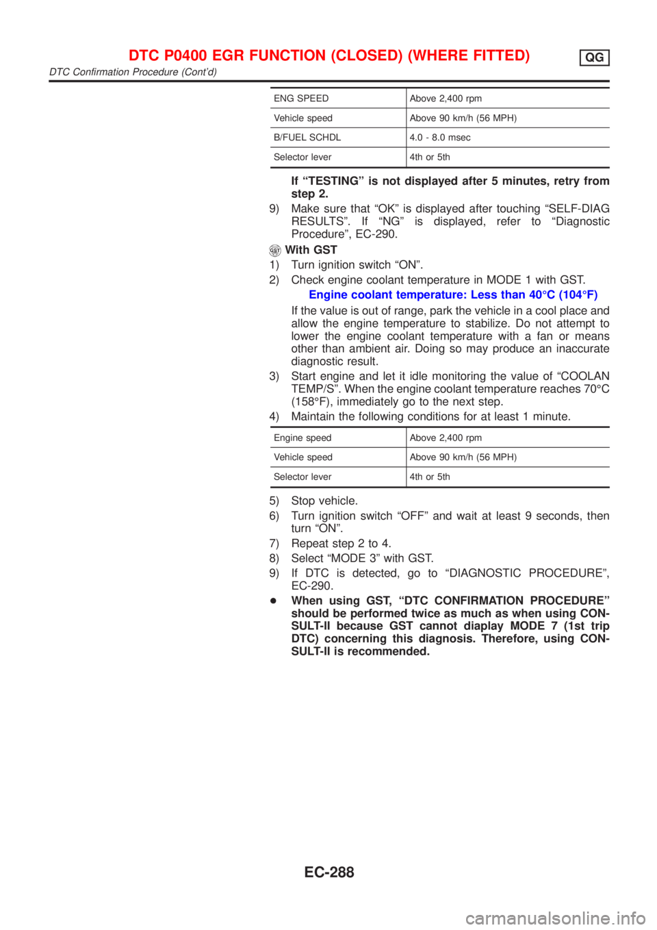
ENG SPEED Above 2,400 rpm
Vehicle speed Above 90 km/h (56 MPH)
B/FUEL SCHDL 4.0 - 8.0 msec
Selector lever 4th or 5th
If ªTESTINGº is not displayed after 5 minutes, retry from
step 2.
9) Make sure that ªOKº is displayed after touching ªSELF-DIAG
RESULTSº. If ªNGº is displayed, refer to ªDiagnostic
Procedureº, EC-290.
With GST
1) Turn ignition switch ªONº.
2) Check engine coolant temperature in MODE 1 with GST.
Engine coolant temperature: Less than 40ÉC (104ÉF)
If the value is out of range, park the vehicle in a cool place and
allow the engine temperature to stabilize. Do not attempt to
lower the engine coolant temperature with a fan or means
other than ambient air. Doing so may produce an inaccurate
diagnostic result.
3) Start engine and let it idle monitoring the value of ªCOOLAN
TEMP/Sº. When the engine coolant temperature reaches 70ÉC
(158ÉF), immediately go to the next step.
4) Maintain the following conditions for at least 1 minute.
Engine speed Above 2,400 rpm
Vehicle speed Above 90 km/h (56 MPH)
Selector lever 4th or 5th
5) Stop vehicle.
6) Turn ignition switch ªOFFº and wait at least 9 seconds, then
turn ªONº.
7) Repeat step 2 to 4.
8) Select ªMODE 3º with GST.
9) If DTC is detected, go to ªDIAGNOSTIC PROCEDUREº,
EC-290.
+When using GST, ªDTC CONFIRMATION PROCEDUREº
should be performed twice as much as when using CON-
SULT-II because GST cannot diaplay MODE 7 (1st trip
DTC) concerning this diagnosis. Therefore, using CON-
SULT-II is recommended.
DTC P0400 EGR FUNCTION (CLOSED) (WHERE FITTED)QG
DTC Confirmation Procedure (Cont'd)
EC-288
Page 589 of 2493
DescriptionNJEC0504SYSTEM DESCRIPTIONNJEC0504S01
Sensor Input Signal to ECMECM func-
tionActuator
Crankshaft position sensor (POS) Engine speed
EGR vol-
ume controlEGR volume control valve Camshaft position sensor (PHASE) Engine speed and cylinder number
Mass air flow sensor Amount of intake air
Engine coolant temperature sensor Engine coolant temperature
Ignition switch Start signal
Throttle position sensor Throttle position
Vehicle speed sensor Vehicle speed
Battery Battery voltage
Air conditioner switch Air conditioner operation
Power steering oil pressure switch Power steering load signal
Electrical load Electrical load signal
PNP switch Park/Neutral position signal
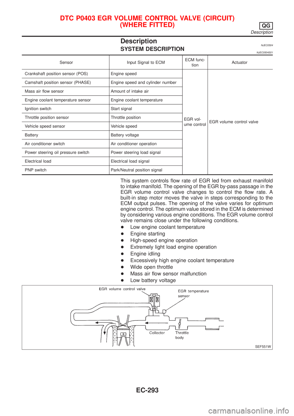
This system controls flow rate of EGR led from exhaust manifold
to intake manifold. The opening of the EGR by-pass passage in the
EGR volume control valve changes to control the flow rate. A
built-in step motor moves the valve in steps corresponding to the
ECM output pulses. The opening of the valve varies for optimum
engine control. The optimum value stored in the ECM is determined
by considering various engine conditions. The EGR volume control
valve remains close under the following conditions.
+Low engine coolant temperature
+Engine starting
+High-speed engine operation
+Extremely light load engine operation
+Engine idling
+Excessively high engine coolant temperature
+Wide open throttle
+Mass air flow sensor malfunction
+Low battery voltage
SEF551W
DTC P0403 EGR VOLUME CONTROL VALVE (CIRCUIT)
(WHERE FITTED)
QG
Description
EC-293
Page 595 of 2493
SEF184UD
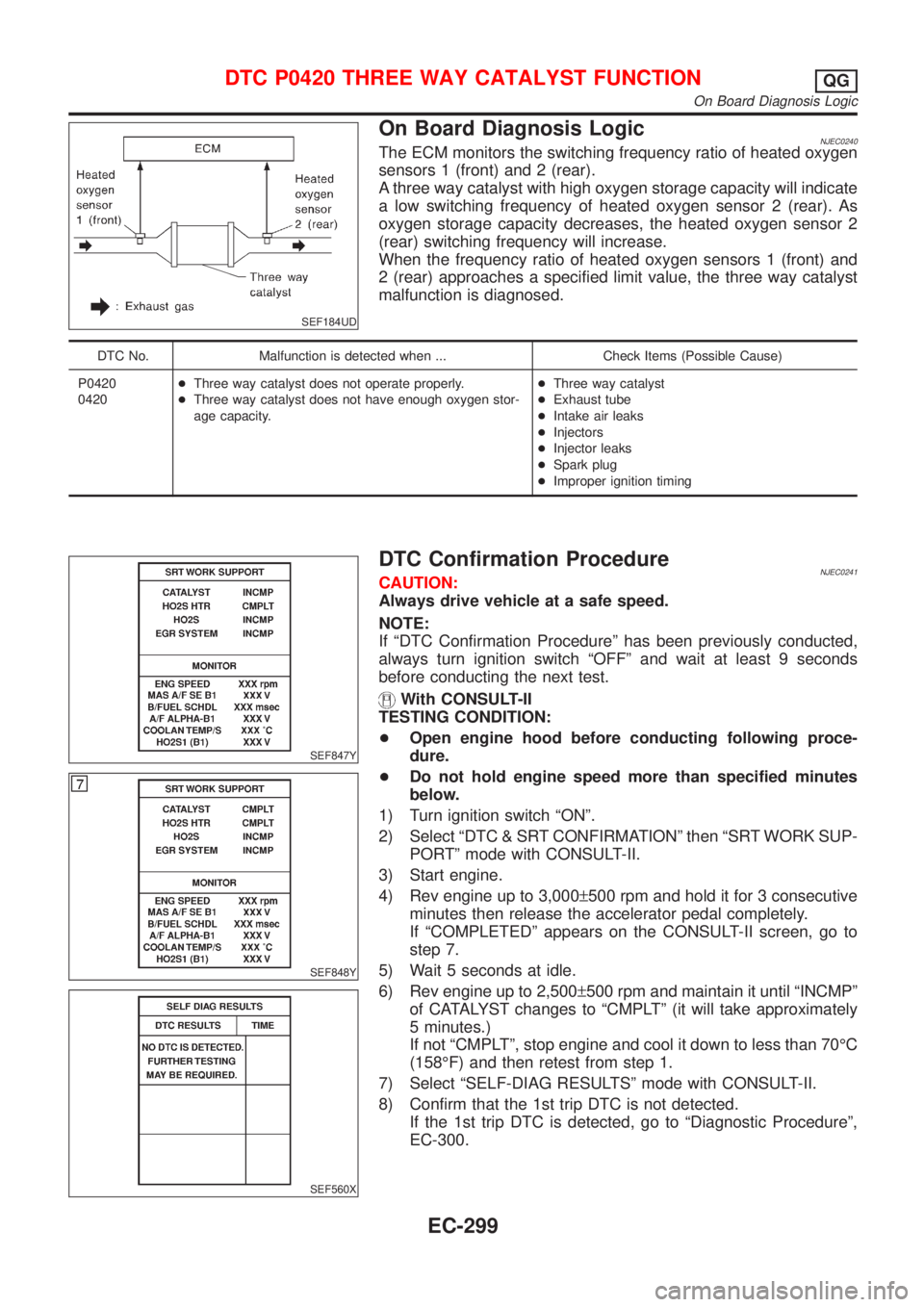
On Board Diagnosis LogicNJEC0240The ECM monitors the switching frequency ratio of heated oxygen
sensors 1 (front) and 2 (rear).
A three way catalyst with high oxygen storage capacity will indicate
a low switching frequency of heated oxygen sensor 2 (rear). As
oxygen storage capacity decreases, the heated oxygen sensor 2
(rear) switching frequency will increase.
When the frequency ratio of heated oxygen sensors 1 (front) and
2 (rear) approaches a specified limit value, the three way catalyst
malfunction is diagnosed.
DTC No. Malfunction is detected when ... Check Items (Possible Cause)
P0420
0420+Three way catalyst does not operate properly.
+Three way catalyst does not have enough oxygen stor-
age capacity.+Three way catalyst
+Exhaust tube
+Intake air leaks
+Injectors
+Injector leaks
+Spark plug
+Improper ignition timing
SEF847Y
SEF848Y
SEF560X
DTC Confirmation ProcedureNJEC0241CAUTION:
Always drive vehicle at a safe speed.
NOTE:
If ªDTC Confirmation Procedureº has been previously conducted,
always turn ignition switch ªOFFº and wait at least 9 seconds
before conducting the next test.
With CONSULT-II
TESTING CONDITION:
+Open engine hood before conducting following proce-
dure.
+Do not hold engine speed more than specified minutes
below.
1) Turn ignition switch ªONº.
2) Select ªDTC & SRT CONFIRMATIONº then ªSRT WORK SUP-
PORTº mode with CONSULT-II.
3) Start engine.
4) Rev engine up to 3,000±500 rpm and hold it for 3 consecutive
minutes then release the accelerator pedal completely.
If ªCOMPLETEDº appears on the CONSULT-II screen, go to
step 7.
5) Wait 5 seconds at idle.
6) Rev engine up to 2,500±500 rpm and maintain it until ªINCMPº
of CATALYST changes to ªCMPLTº (it will take approximately
5 minutes.)
If not ªCMPLTº, stop engine and cool it down to less than 70ÉC
(158ÉF) and then retest from step 1.
7) Select ªSELF-DIAG RESULTSº mode with CONSULT-II.
8) Confirm that the 1st trip DTC is not detected.
If the 1st trip DTC is detected, go to ªDiagnostic Procedureº,
EC-300.
DTC P0420 THREE WAY CATALYST FUNCTIONQG
On Board Diagnosis Logic
EC-299
Page 600 of 2493
DescriptionNJEC0248SYSTEM DESCRIPTIONNJEC0248S01
Sensor Input Signal to ECMECM func-
tionActuator
Crankshaft position sensor (POS) Engine speed
EVAP can-
ister purge
controlEVAP canister purge volume
control solenoid valve Camshaft position sensor (PHASE) Engine speed and cylinder number
Mass air flow sensor Amount of intake air
Engine coolant temperature sensor Engine coolant temperature
Battery Battery voltage
Ignition switch Start signal
Closed throttle position switch* Closed throttle position
Throttle position sensor Throttle position
Heated oxygen sensor 1 (front)Density of oxygen in exhaust gas
(Mixture ratio feedback signal)
Fuel tank temperature sensor* Fuel temperature in fuel tank
Vehicle speed sensor Vehicle speed
*: If so equipped
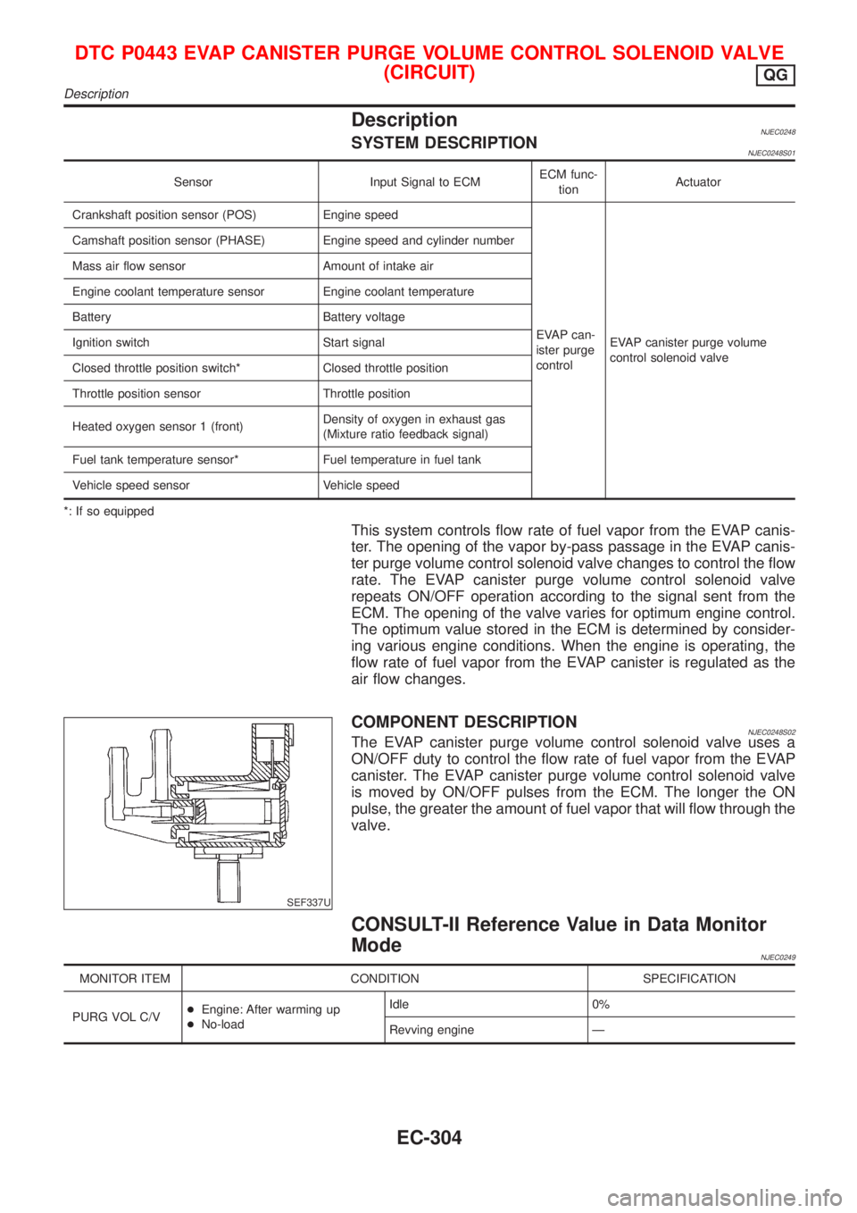
This system controls flow rate of fuel vapor from the EVAP canis-
ter. The opening of the vapor by-pass passage in the EVAP canis-
ter purge volume control solenoid valve changes to control the flow
rate. The EVAP canister purge volume control solenoid valve
repeats ON/OFF operation according to the signal sent from the
ECM. The opening of the valve varies for optimum engine control.
The optimum value stored in the ECM is determined by consider-
ing various engine conditions. When the engine is operating, the
flow rate of fuel vapor from the EVAP canister is regulated as the
air flow changes.
SEF337U
COMPONENT DESCRIPTIONNJEC0248S02The EVAP canister purge volume control solenoid valve uses a
ON/OFF duty to control the flow rate of fuel vapor from the EVAP
canister. The EVAP canister purge volume control solenoid valve
is moved by ON/OFF pulses from the ECM. The longer the ON
pulse, the greater the amount of fuel vapor that will flow through the
valve.
CONSULT-II Reference Value in Data Monitor
Mode
NJEC0249
MONITOR ITEM CONDITION SPECIFICATION
PURG VOL C/V+Engine: After warming up
+No-loadIdle 0%
Revving engine Ð
DTC P0443 EVAP CANISTER PURGE VOLUME CONTROL SOLENOID VALVE
(CIRCUIT)
QG
Description
EC-304
Page 604 of 2493

4 CHECK EVAP CANISTER PURGE VOLUME CONTROL SOLENOID VALVE
Refer to ªComponent Inspectionº EC-308.
OK or NG
OK©GO TO 5.
NG©Replace EVAP canister purge volume control solenoid valve.
5 CHECK INTERMITTENT INCIDENT
Perform ªTROUBLE DIAGNOSIS FOR INTERMITTENT INCIDENTº, EC-144.
©INSPECTION END
SEF677Y
SEF079X
Component InspectionNJEC0255EVAP CANISTER PURGE VOLUME CONTROL
SOLENOID VALVE
NJEC0255S01With CONSULT-II
1) Start engine.
2) Perform ªPURG VOL CONT/Vº in ªACTIVE TESTº mode with
CONSULT-II. Check that engine speed varies according to the
valve opening.
If OK, inspection end. If NG, go to following step.
3) Check air passage continuity.
Condition
PURG VOL CONT/V valueAir passage continuity
between A and B
100.0% Yes
0.0% No
If NG or operation takes more than 1 second, replace the
EVAP canister purge volume control solenoid valve.
Without CONSULT-II
Check air passage continuity.
ConditionAir passage continuity
between A and B
12V direct current supply between ter-
minalsYe s
No supply No
If NG or operation takes more than 1 second, replace the EVAP
canister purge volume control solenoid valve.
DTC P0443 EVAP CANISTER PURGE VOLUME CONTROL SOLENOID VALVE
(CIRCUIT)
QG
Diagnostic Procedure (Cont'd)
EC-308