Page 1800 of 2493
ComponentsNJST0017
JST875C
1. Air bag module
2. Steering wheel
3. Spiral cable
4. Column cover5. Combination switch
6. Steering column assembly
7. Clip8. Hole cover
9. Lower joint
10. Lower cover
CAUTION:
+The rotation of the spiral cable (SRS ªAir bagº component
part) is limited. If the steering gear must be removed, set
the front wheels in the straight-ahead direction. Do not
rotate the steering column while the steering gear is
removed.
+Remove the steering wheel before removing the steering
lower joint to avoid damaging the SRS spiral cable.
SBF812E
Removal and InstallationNJST0018STEERING WHEELNJST0018S01+Remove air bag module and spiral cable.
Refer to RS-29, ªRemoval Ð Air Bag Module and Spiral
Cableº.
STEERING WHEEL AND STEERING COLUMN
Components
ST-10
Page 1801 of 2493

SRS266
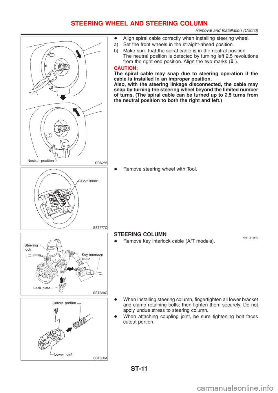
+Align spiral cable correctly when installing steering wheel.
a) Set the front wheels in the straight-ahead position.
b) Make sure that the spiral cable is in the neutral position.
The neutral position is detected by turning left 2.5 revolutions
from the right end position. Align the two marks (
).
CAUTION:
The spiral cable may snap due to steering operation if the
cable is installed in an improper position.
Also, with the steering linkage disconnected, the cable may
snap by turning the steering wheel beyond the limited number
of turns. (The spiral cable can be turned up to 2.5 turns from
the neutral position to both the right and left.)
SST777C
+Remove steering wheel with Tool.
SST329C
STEERING COLUMNNJST0018S02+Remove key interlock cable (A/T models).
SST800A
+When installing steering column, fingertighten all lower bracket
and clamp retaining bolts; then tighten them securely. Do not
apply undue stress to steering column.
+When attaching coupling joint, be sure tightening bolt faces
cutout portion.
STEERING WHEEL AND STEERING COLUMN
Removal and Installation (Cont'd)
ST-11
Page 1802 of 2493
SST491C
+Align slit of lower joint with projection on dust cover. Insert joint
until surface A contacts surface B.
CAUTION:
After installation, turn steering wheel to make sure it moves
smoothly. Ensure the number of turns are the same from the
straight forward position to left and right locks. Be sure that
the steering wheel is in a neutral position when driving
straight ahead.
STEERING WHEEL AND STEERING COLUMN
Removal and Installation (Cont'd)
ST-12
Page 1803 of 2493
Disassembly and Assembly=NJST0019
YST008
1. Combination switch
2. Lock nut
3. Jacket tube assembly4. Column shaft assembly
5. Clip
6. Lower seal cover7. Hole cover
8. Steering column lower cover
SST490C
+When disassembling and assembling, unlock steering lock
with key.
+Remove combination switch.
+Install lock nut on steering column shaft and tighten the nut.
SST741A
+Steering lock
a) Break self-shear type screws with a drill or other appropriate
tool.
STEERING WHEEL AND STEERING COLUMN
Disassembly and Assembly
ST-13
Page 1804 of 2493
SST742A
b) Install new self-shear type screws and then cut off self-shear
type screw heads.
SST855C
InspectionNJST0020+When steering wheel does not turn smoothly, check the steer-
ing column as follows and replace damaged parts.
a) Check column bearings for damage or unevenness. Lubricate
with recommended multi-purpose grease or replace steering
column as an assembly, if necessary.
b) Check jacket tube for deformation or breakage. Replace if
necessary.
+When the vehicle comes into a light collision, check length ªLº.
Steering column length ªLº:
Refer to SDS, ST-29.
If out of the specifications, replace steering column as an assem-
bly.
SST582B
TILT MECHANISMNJST0020S01+After installing steering column, check tilt mechanism opera-
tion.
STEERING WHEEL AND STEERING COLUMN
Disassembly and Assembly (Cont'd)
ST-14
Page 1806 of 2493
Removal and InstallationNJST0022
SST878CA
1. Lower joint
2. Washer
3. Gear and linkage assembly4. Upper gear housing mounting
bracket
5. Rack mounting insulator6. Lower gear housing mounting
bracket
7. Cotter pin
SFA455BA
CAUTION:
+The rotation of the spiral cable (SRS ªAir bagº component
part) is limited. If the steering gear must be removed, set
the front wheels in the straight-ahead direction. Do not
rotate the steering column while the steering gear is
removed.
+Remove the steering wheel before removing the steering
lower joint to avoid damaging the SRS spiral cable.
+Detach tie-rod outer sockets from knuckle arms with Tool.
1. Remove stabilizer fixing bolts. Refer to SU-11, ªRemoval and
Installationº.
2. Disconnect lower joint.
3. Remove gear housing mounting bracket fixing bolts.
4. Remove steering gear assembly.
POWER STEERING GEAR AND LINKAGE
Removal and Installation
ST-16
Page 1807 of 2493

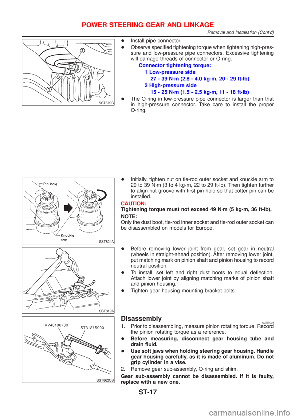
SST879C
+Install pipe connector.
+Observe specified tightening torque when tightening high-pres-
sure and low-pressure pipe connectors. Excessive tightening
will damage threads of connector or O-ring.
Connector tightening torque:
1 Low-pressure side
27 - 39 N´m (2.8 - 4.0 kg-m, 20 - 29 ft-lb)
2 High-pressure side
15 - 25 N´m (1.5 - 2.5 kg-m, 11 - 18 ft-lb)
+The O-ring in low-pressure pipe connector is larger than that
in high-pressure connector. Take care to install the proper
O-ring.
SST824A
+Initially, tighten nut on tie-rod outer socket and knuckle arm to
29 to 39 N´m (3 to 4 kg-m, 22 to 29 ft-lb). Then tighten further
to align nut groove with first pin hole so that cotter pin can be
installed.
CAUTION:
Tightening torque must not exceed 49 N´m (5 kg-m, 36 ft-lb).
NOTE:
Only the dust boot, tie-rod inner socket and tie-rod outer socket can
be disassembled on models for Europe.
SST819A
+Before removing lower joint from gear, set gear in neutral
(wheels in straight-ahead position). After removing lower joint,
put matching mark on pinion shaft and pinion housing to record
neutral position.
+To install, set left and right dust boots to equal deflection.
Attach lower joint by aligning matching marks of pinion shaft
and pinion housing.
+Tighten gear housing mounting bracket bolts.
SST862CB
DisassemblyNJST00231. Prior to disassembling, measure pinion rotating torque. Record
the pinion rotating torque as a reference.
+Before measuring, disconnect gear housing tube and
drain fluid.
+Use soft jaws when holding steering gear housing. Handle
gear housing carefully, as it is made of aluminum. Do not
grip cylinder in a vise.
2. Remove gear sub-assembly, O-ring and shim.
Gear sub-assembly cannot be disassembled. If it is faulty,
replace with a new one.
POWER STEERING GEAR AND LINKAGE
Removal and Installation (Cont'd)
ST-17
Page 1819 of 2493
General SpecificationsNJST0032
Steering modelPower steering
Steering gear typePR25T
Steering overall gear ratio16.8
Turns of steering wheel (Lock to lock)2.9
Steering column typeCollapsible, tilt
Steering WheelNJST0033
Steering wheel axial play mm (in)0 (0)
Steering wheel play mm (in)35 (1.38) or less
Movement of gear housing mm (in)±2(±0.08) or less
Steering ColumnNJST0034
Steering column length ªLº mm (in) 545 - 547 (21.46 - 21.54)
SST855C
SERVICE DATA AND SPECIFICATIONS (SDS)
General Specifications
ST-29