Page 719 of 2493
6 CHECK AIR CONTROL VALVE (POWER STEERING) OPERATION-II
Check the vacuum hose for vacuum existence when steering wheel is turned.
SEF162Z
Vacuum should exist.
OK or NG
OK©GO TO 9.
NG©GO TO 7.
7 CHECK VACUUM PORT
1. Stop engine.
2. Disconnect the vacuum hose connected to the air control valve (Power steering) at the vacuum port.
3. Blow air into vacuum port.
4. Check that air flows freely.
SEF924Y
OK or NG
OK©GO TO 8.
NG©Repair or clean vacuum port.
IDLE AIR CONTROL VALVE (IACV) Ð AUXILIARY AIR CONTROL
(AAC) VALVE
QG
Diagnostic Procedure (Cont'd)
EC-423
Page 766 of 2493
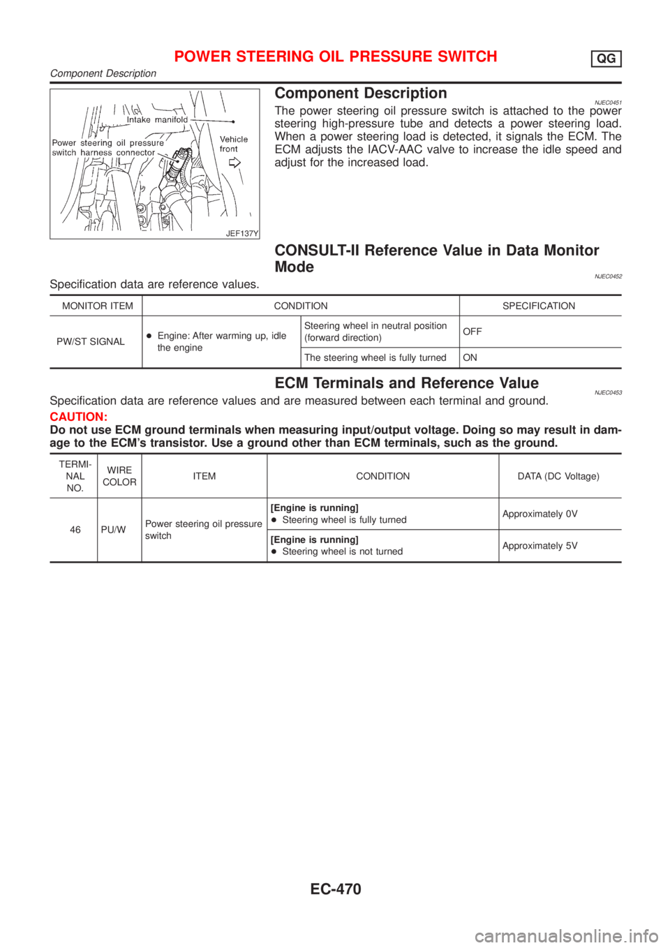
JEF137Y
Component DescriptionNJEC0451The power steering oil pressure switch is attached to the power
steering high-pressure tube and detects a power steering load.
When a power steering load is detected, it signals the ECM. The
ECM adjusts the IACV-AAC valve to increase the idle speed and
adjust for the increased load.
CONSULT-II Reference Value in Data Monitor
Mode
NJEC0452Specification data are reference values.
MONITOR ITEM CONDITION SPECIFICATION
PW/ST SIGNAL+Engine: After warming up, idle
the engineSteering wheel in neutral position
(forward direction)OFF
The steering wheel is fully turned ON
ECM Terminals and Reference ValueNJEC0453Specification data are reference values and are measured between each terminal and ground.
CAUTION:
Do not use ECM ground terminals when measuring input/output voltage. Doing so may result in dam-
age to the ECM's transistor. Use a ground other than ECM terminals, such as the ground.
TERMI-
NAL
NO.WIRE
COLORITEM CONDITION DATA (DC Voltage)
46 PU/WPower steering oil pressure
switch[Engine is running]
+Steering wheel is fully turnedApproximately 0V
[Engine is running]
+Steering wheel is not turnedApproximately 5V
POWER STEERING OIL PRESSURE SWITCHQG
Component Description
EC-470
Page 769 of 2493

4 CHECK GROUND CIRCUIT
1. Turn ignition switch ªOFFº.
2. Disconnect power steering oil pressure switch harness connector.
3. Check harness continuity between power steering oil pressure switch harness terminal 2 and engine ground.
Refer to wiring diagram.
Continuity should exist.
4. Also check harness for short to ground and short to power.
OK or NG
OK©GO TO 5.
NG©Repair open circuit or short to ground or short to power in harness or connectors.
5 CHECK INPUT SIGNAL CIRCUIT
1. Disconnect ECM harness connector.
2. Check harness continuity between ECM terminal 46 and power steering oil pressure switch harness terminal 1.
Refer to wiring diagram.
Continuity should exist.
3. Also check harness for short to ground and short to power.
OK or NG
OK©GO TO 7.
NG©GO TO 6.
6 DETECT MALFUNCTIONING PART
Check the harness for open or short between ECM and power steering oil pressure switch.
©Repair open circuit or short to ground or short to power in harness or connectors.
7 CHECK POWER STEERING OIL PRESSURE SWITCH
Refer to ªComponent Inspectionº, EC-473.
OK or NG
OK©GO TO 8.
NG©Replace power steering oil pressure switch.
8 CHECK INTERMITTENT INCIDENT
Perform ªTROUBLE DIAGNOSIS FOR INTERMITTENT INCIDENTº, EC-144.
©INSPECTION END
Component InspectionNJEC0455POWER STEERING OIL PRESSURE SWITCHNJEC0455S011. Disconnect power steering oil pressure switch harness con-
nector then start engine.
2. Check continuity between terminals 1 and 2.
Refer to wiring diagram.
Conditions Continuity
Steering wheel is being fully turned. Yes
Steering wheel is not being turned. No
POWER STEERING OIL PRESSURE SWITCHQG
Diagnostic Procedure (Cont'd)
EC-473
Page 785 of 2493
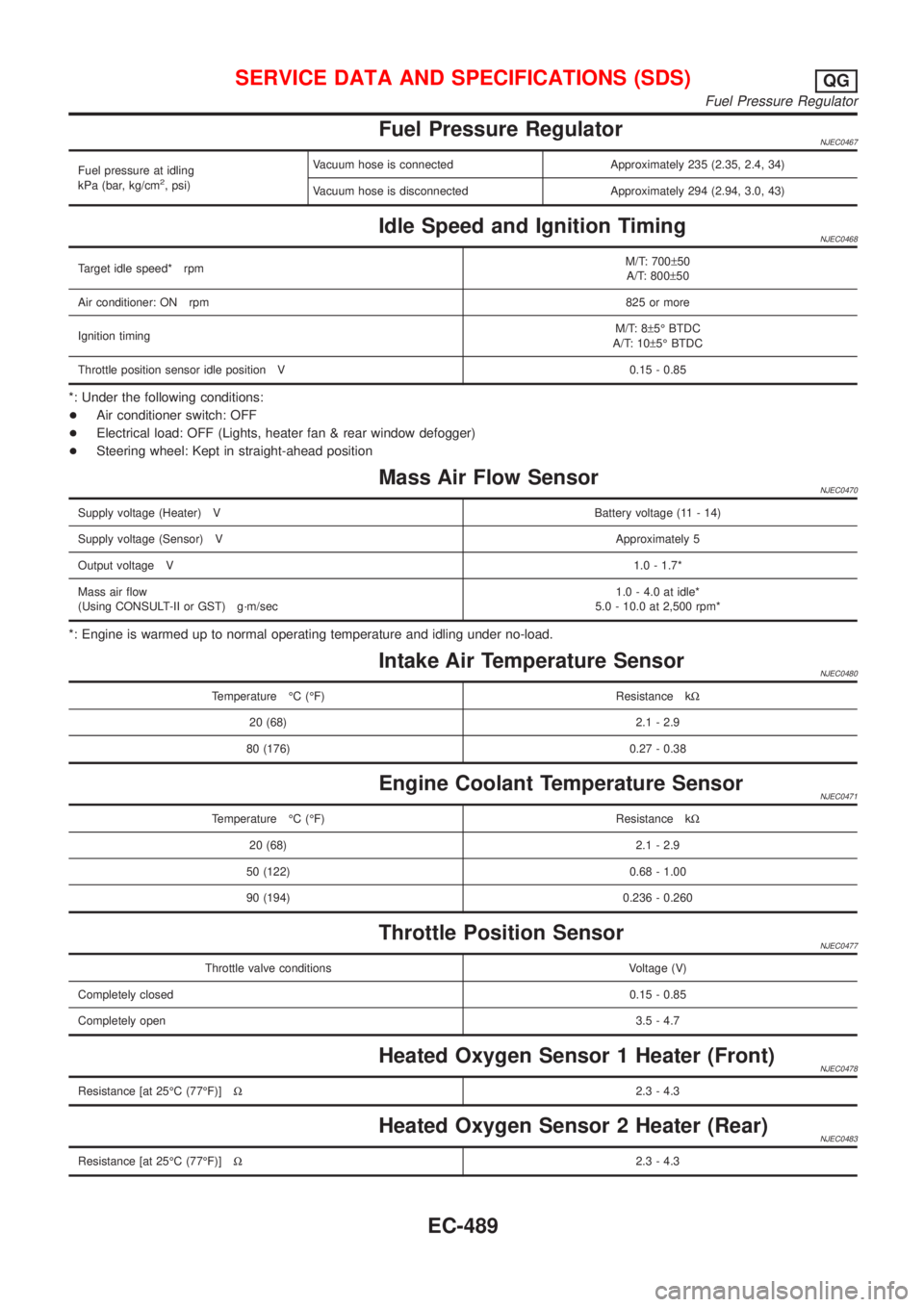
Fuel Pressure RegulatorNJEC0467
Fuel pressure at idling
kPa (bar, kg/cm2, psi)Vacuum hose is connected Approximately 235 (2.35, 2.4, 34)
Vacuum hose is disconnected Approximately 294 (2.94, 3.0, 43)
Idle Speed and Ignition TimingNJEC0468
Target idle speed* rpmM/T: 700±50
A/T: 800±50
Air conditioner: ON rpm825 or more
Ignition timingM/T: 8±5É BTDC
A/T: 10±5É BTDC
Throttle position sensor idle position V 0.15 - 0.85
*: Under the following conditions:
+Air conditioner switch: OFF
+Electrical load: OFF (Lights, heater fan & rear window defogger)
+Steering wheel: Kept in straight-ahead position
Mass Air Flow SensorNJEC0470
Supply voltage (Heater) VBattery voltage (11 - 14)
Supply voltage (Sensor) VApproximately 5
Output voltage V1.0 - 1.7*
Mass air flow
(Using CONSULT-II or GST) g´m/sec1.0 - 4.0 at idle*
5.0 - 10.0 at 2,500 rpm*
*: Engine is warmed up to normal operating temperature and idling under no-load.
Intake Air Temperature SensorNJEC0480
Temperature ÉC (ÉF) Resistance kW
20 (68) 2.1 - 2.9
80 (176) 0.27 - 0.38
Engine Coolant Temperature SensorNJEC0471
Temperature ÉC (ÉF) Resistance kW
20 (68) 2.1 - 2.9
50 (122) 0.68 - 1.00
90 (194) 0.236 - 0.260
Throttle Position SensorNJEC0477
Throttle valve conditions Voltage (V)
Completely closed0.15 - 0.85
Completely open3.5 - 4.7
Heated Oxygen Sensor 1 Heater (Front)NJEC0478
Resistance [at 25ÉC (77ÉF)]W2.3 - 4.3
Heated Oxygen Sensor 2 Heater (Rear)NJEC0483
Resistance [at 25ÉC (77ÉF)]W2.3 - 4.3
SERVICE DATA AND SPECIFICATIONS (SDS)QG
Fuel Pressure Regulator
EC-489
Page 832 of 2493
Basic InspectionNJEC0632Precaution:
Perform Basic Inspection without electrical or mechanical
loads applied;
+Headlamp switch is OFF,
+On vehicles equipped with daytime light systems, set
lighting switch to the 1st position to light only small
lamps.
+Air conditioner switch is OFF,
+Rear defogger switch is OFF,
+Steering wheel is in the straight-ahead position, etc.
1 INSPECTION START
1. Check service records for any recent repairs that may indicate a related problem.
2. Check the current need for scheduled maintenance, especially for fuel filter and air cleaner filter. Refer to MA-4, ªPeri-
odic Maintenanceº.
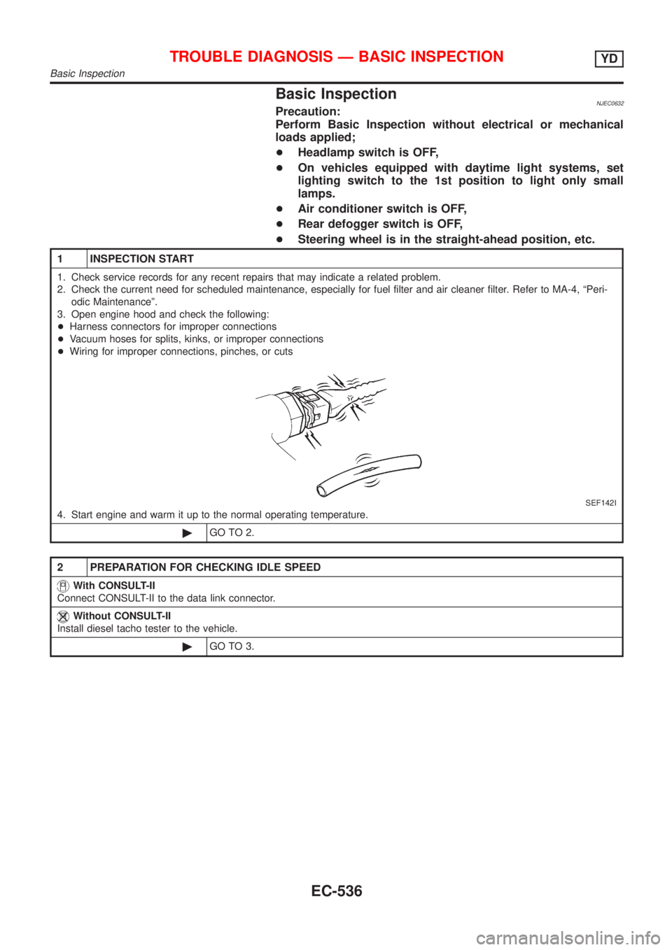
3. Open engine hood and check the following:
+Harness connectors for improper connections
+Vacuum hoses for splits, kinks, or improper connections
+Wiring for improper connections, pinches, or cuts
SEF142I
4. Start engine and warm it up to the normal operating temperature.
©GO TO 2.
2 PREPARATION FOR CHECKING IDLE SPEED
With CONSULT-II
Connect CONSULT-II to the data link connector.
Without CONSULT-II
Install diesel tacho tester to the vehicle.
©GO TO 3.
TROUBLE DIAGNOSIS Ð BASIC INSPECTIONYD
Basic Inspection
EC-536
Page 1035 of 2493
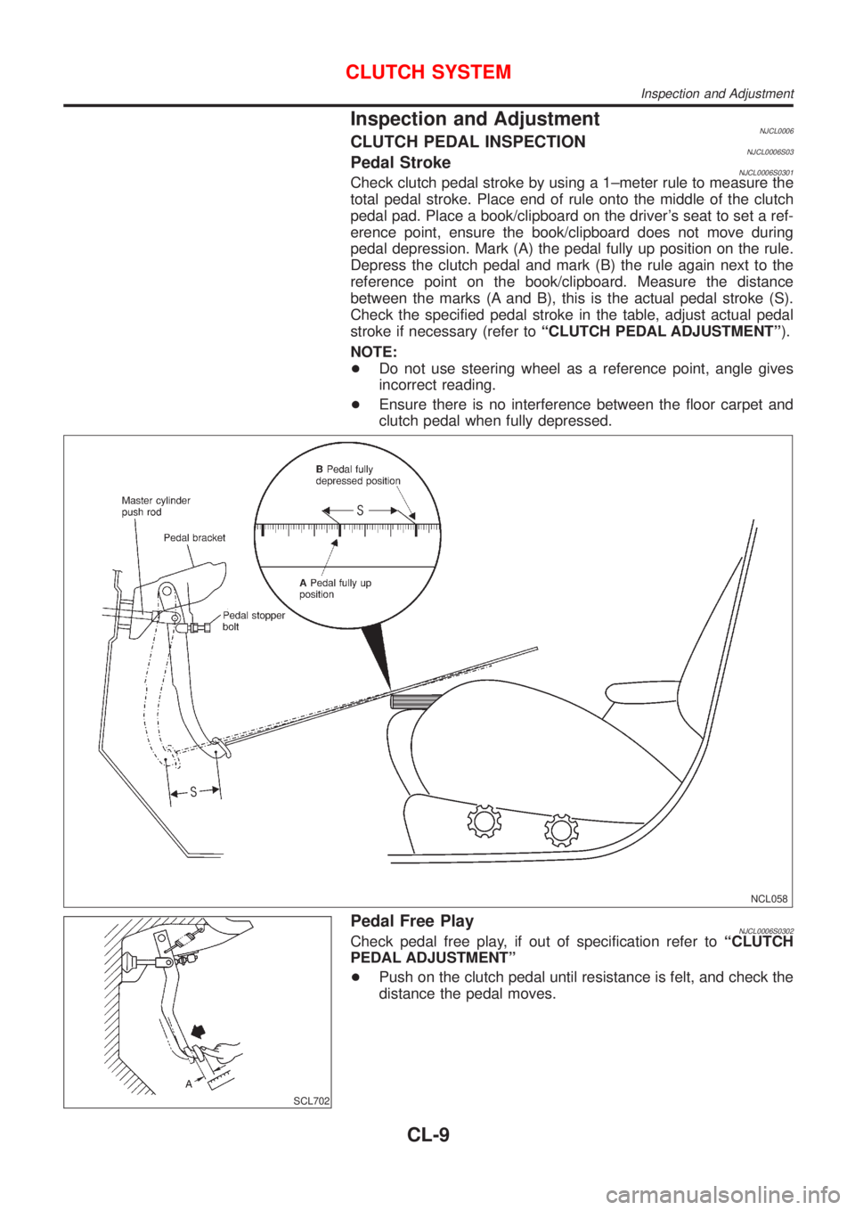
Inspection and AdjustmentNJCL0006CLUTCH PEDAL INSPECTIONNJCL0006S03Pedal StrokeNJCL0006S0301Check clutch pedal stroke by using a 1±meter rule to measure the
total pedal stroke. Place end of rule onto the middle of the clutch
pedal pad. Place a book/clipboard on the driver's seat to set a ref-
erence point, ensure the book/clipboard does not move during
pedal depression. Mark (A) the pedal fully up position on the rule.
Depress the clutch pedal and mark (B) the rule again next to the
reference point on the book/clipboard. Measure the distance
between the marks (A and B), this is the actual pedal stroke (S).
Check the specified pedal stroke in the table, adjust actual pedal
stroke if necessary (refer toªCLUTCH PEDAL ADJUSTMENTº).
NOTE:
+Do not use steering wheel as a reference point, angle gives
incorrect reading.
+Ensure there is no interference between the floor carpet and
clutch pedal when fully depressed.
NCL058
SCL702
Pedal Free PlayNJCL0006S0302Check pedal free play, if out of specification refer toªCLUTCH
PEDAL ADJUSTMENTº
+Push on the clutch pedal until resistance is felt, and check the
distance the pedal moves.
CLUTCH SYSTEM
Inspection and Adjustment
CL-9
Page 1647 of 2493
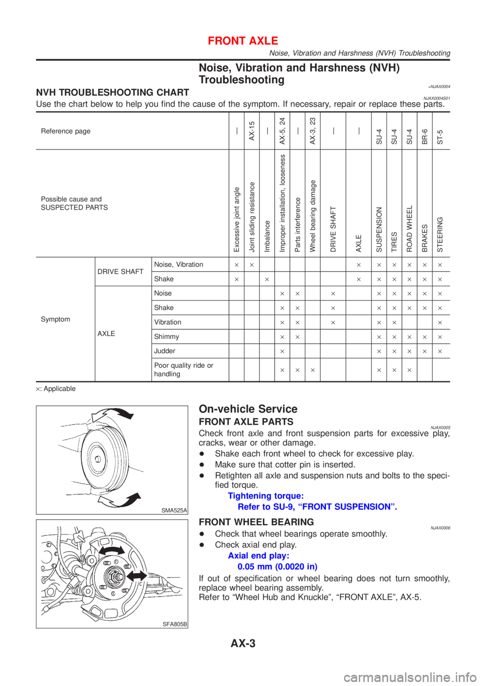
Noise, Vibration and Harshness (NVH)
Troubleshooting
=NJAX0004NVH TROUBLESHOOTING CHARTNJAX0004S01Use the chart below to help you find the cause of the symptom. If necessary, repair or replace these parts.
Reference pageÐ
AX-15
Ð
AX-5, 24
Ð
AX-3, 23
Ð
Ð
SU-4
SU-4
SU-4
BR-6
ST-5
Possible cause and
SUSPECTED PARTS
Excessive joint angle
Joint sliding resistance
Imbalance
Improper installation, looseness
Parts interference
Wheel bearing damage
DRIVE SHAFT
AXLE
SUSPENSION
TIRES
ROAD WHEEL
BRAKES
STEERING
SymptomDRIVE SHAFTNoise, Vibration´´ ´ ´´´´´
Shake´ ´ ´ ´´´´´
AXLENoise´´ ´ ´´´´´
Shake´´ ´ ´´´´´
Vibration´´ ´ ´´ ´
Shimmy´´ ´´´´´
Judder´ ´´´´´
Poor quality ride or
handling´´´ ´´´
´: Applicable
SMA525A
On-vehicle Service
FRONT AXLE PARTSNJAX0005Check front axle and front suspension parts for excessive play,
cracks, wear or other damage.
+Shake each front wheel to check for excessive play.
+Make sure that cotter pin is inserted.
+Retighten all axle and suspension nuts and bolts to the speci-
fied torque.
Tightening torque:
Refer to SU-9, ªFRONT SUSPENSIONº.
SFA805B
FRONT WHEEL BEARINGNJAX0006+Check that wheel bearings operate smoothly.
+Check axial end play.
Axial end play:
0.05 mm (0.0020 in)
If out of specification or wheel bearing does not turn smoothly,
replace wheel bearing assembly.
Refer to ªWheel Hub and Knuckleº, ªFRONT AXLEº, AX-5.
FRONT AXLE
Noise, Vibration and Harshness (NVH) Troubleshooting
AX-3
Page 1652 of 2493
SAX008
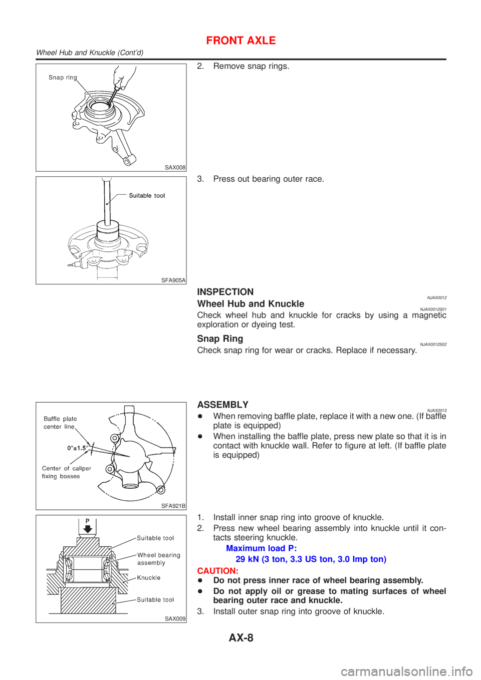
2. Remove snap rings.
SFA905A
3. Press out bearing outer race.
INSPECTIONNJAX0012Wheel Hub and KnuckleNJAX0012S01Check wheel hub and knuckle for cracks by using a magnetic
exploration or dyeing test.
Snap RingNJAX0012S02Check snap ring for wear or cracks. Replace if necessary.
SFA921B
ASSEMBLYNJAX0013+When removing baffle plate, replace it with a new one. (If baffle
plate is equipped)
+When installing the baffle plate, press new plate so that it is in
contact with knuckle wall. Refer to figure at left. (If baffle plate
is equipped)
SAX009
1. Install inner snap ring into groove of knuckle.
2. Press new wheel bearing assembly into knuckle until it con-
tacts steering knuckle.
Maximum load P:
29 kN (3 ton, 3.3 US ton, 3.0 Imp ton)
CAUTION:
+Do not press inner race of wheel bearing assembly.
+Do not apply oil or grease to mating surfaces of wheel
bearing outer race and knuckle.
3. Install outer snap ring into groove of knuckle.
FRONT AXLE
Wheel Hub and Knuckle (Cont'd)
AX-8