Page 973 of 2493

DescriptionNJEC0760SYSTEM DESCRIPTIONNJEC0760S01
Sensor Input Signal to ECMECM
Func-
tionActuator
Crankshaft position sensor
(TDC)Engine speed
Glow
controlGlow lamp,
Glow relay
¯
Glow plugs Engine coolant tempera-
ture sensorEngine coolant tem-
perature
When engine coolant temperature is more than approximately
75ÉC (167ÉF), the glow relay turns off.
When coolant temperature is lower than approximately 75ÉC
(167ÉF):
+Ignition switch ON
After ignition switch has turned to ON, the glow relay turns ON
for a certain period of time in relation to engine coolant
temperature, allowing current to flow through glow plug.
+Cranking
The glow relay turns ON, allowing current to flow through glow
plug.
+Starting
After engine has started, current continues to flow through
glow plug (after-glow mode) for a certain period in relation to
engine coolant temperature.
The glow indicator lamp turns ON for a certain period of time in
relation to engine cooalnt temperature at the time glow relay is
turned ON.
SEF376Y
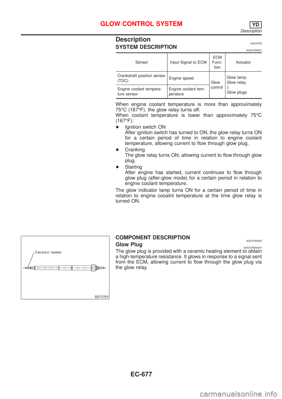
COMPONENT DESCRIPTIONNJEC0760S02Glow PlugNJEC0760S0201The glow plug is provided with a ceramic heating element to obtain
a high-temperature resistance. It glows in response to a signal sent
from the ECM, allowing current to flow through the glow plug via
the glow relay.
GLOW CONTROL SYSTEMYD
Description
EC-677
Page 974 of 2493
ECM Terminals and Reference ValueNJEC0761Specification data are reference values and are measured between each terminal and ground.
CAUTION:
Do not use ECM ground terminals when measuring input/output voltage. Doing so may result in dam-
age to the ECM's transistor. Use a ground other than ECM terminals, such as the ground.
TERMI-
NAL
NO.WIRE
COLORITEM CONDITION DATA (DC Voltage)
214 W/B Glow relay Refer to ªSYSTEM DESCRIPTIONº, EC-677.
508 OR Glow indicator lamp[Ignition switch ªONº]
+Glow indicator lamp is ªONºApproximately 1V
[Ignition switch ªONº]
+Glow indicator lamp is ªOFFºBATTERY VOLTAGE
(11 - 14V)
GLOW CONTROL SYSTEMYD
ECM Terminals and Reference Value
EC-678
Page 976 of 2493
Diagnostic ProcedureNJEC0763
1 INSPECTION START
Check fuel level, fuel supplying system, starter motor, etc.
OK or NG
OK©GO TO 2.
NG©Correct.
2 CHECK INSTALLATION
Check that glow plug nut and all glow plug connecting plate nuts are installed properly.
SEF392YA
OK or NG
OK (With CONSULT-II)©GO TO 3.
OK (Without CONSULT-
II)©GO TO 4.
NG©Install properly.
3 CHECK GLOW INDICATOR LAMP OPERATION
With CONSULT-II
1. Turn ignition switch ªONº.
2. Select ªCOOLAN TEMP/Sº in ªDATA MONITORº mode with CONSULT-II.
3. Confirm that ªCOOLAN TEMP/Sº indicates below 75ÉC (167ÉF). If it indicates above 75ÉC (167ÉF), cool down engine.
SEF013Y
4. Turn ignition switch ªOFFº, wait at least 5 seconds and then turn ªONº.
5. Make sure that glow indicator lamp is turned ªONº for 1.5 seconds or more after turning ignition switch ªONº, and then
turned ªOFFº.
OK or NG
OK©GO TO 5.
NG©GO TO 6.
GLOW CONTROL SYSTEMYD
Diagnostic Procedure
EC-680
Page 977 of 2493
4 CHECK GLOW INDICATOR LAMP OPERATION
Without CONSULT-II
1. Turn ignition switch ªONº.
2. Confirm that the voltage between ECM terminal 347 (Engine coolant temperature sensor signal) and ground is above
1.36V. If it is below 1.36V, cool down engine.
SEF442Z
3. Turn ignition switch ªOFFº, wait at least 5 seconds and then turn ªONº.
4. Make sure that glow indicator lamp is turned ªONº for 1.5 seconds or more after turning ignition switch ªONº, and then
turned ªOFFº.
OK or NG
OK©GO TO 5.
NG©GO TO 6.
5 CHECK GLOW CONTROL SYSTEM OVERALL FUNCTION
1. Turn ignition switch ªOFFº.
2. Set voltmeter probe between glow plug and engine body.
3. Turn ignition switch ªONº.
4. Check the voltage between glow plug and engine body under the following conditions.
SEF431Y
OK or NG
OK©INSPECTION END
NG©GO TO 11.
GLOW CONTROL SYSTEMYD
Diagnostic Procedure (Cont'd)
EC-681
Page 978 of 2493

6 CHECK GLOW INDICATOR LAMP POWER SUPPLY CIRCUIT
1. Turn ignition switch ªOFFº.
2. Disconnect combination meter harness connector M32 or M152 or M171.
3. Turn ignition switch ªONº.
4. Check voltage between combination meter terminal 40 or 17 or 1 and ground with CONSULT-II or tester.
YEC060A
OK or NG
OK©GO TO 8.
NG©GO TO 7.
7 DETECT MALFUNCTIONING PART
Check the following.
1. Fuse block (J/B) connector M1
2. 10A fuse
3. Harness for open or short between combination meter and fuse
©Repair open circuit or short to ground or short to power in harness or connectors.
8 CHECK GLOW INDICATOR LAMP OUTPUT SIGNAL CIRCUIT FOR OPEN AND SHORT
1. Turn ignition switch ªOFFº.
2. Disconnect ECM harness connector.
3. Disconnect combination meter harness connector M171.
4. Check harness continuity between ECM terminal 508 and combination meter terminal 17. Refer to Wiring Diagram.
Continuity should exist.
5. Also check harness for short to ground and short to power.
OK or NG
OK©GO TO 10.
NG©GO TO 9.
9 DETECT MALFUNCTIONING PART
Check the following.
1. Harness connectors M63, F102
2. Harness for open or short between combination meter and ECM
©Repair open circuit or short to ground or short to power in harness or connectors.
10 CHECK COMBINATION METER
Check combination meter and glow indicator lamp. Refer to EL-89, ªMeter and Gaugesº.
OK or NG
OK©GO TO 18.
NG©Repair or replace combination meter or glow indicator lamp.
GLOW CONTROL SYSTEMYD
Diagnostic Procedure (Cont'd)
EC-682
Page 979 of 2493

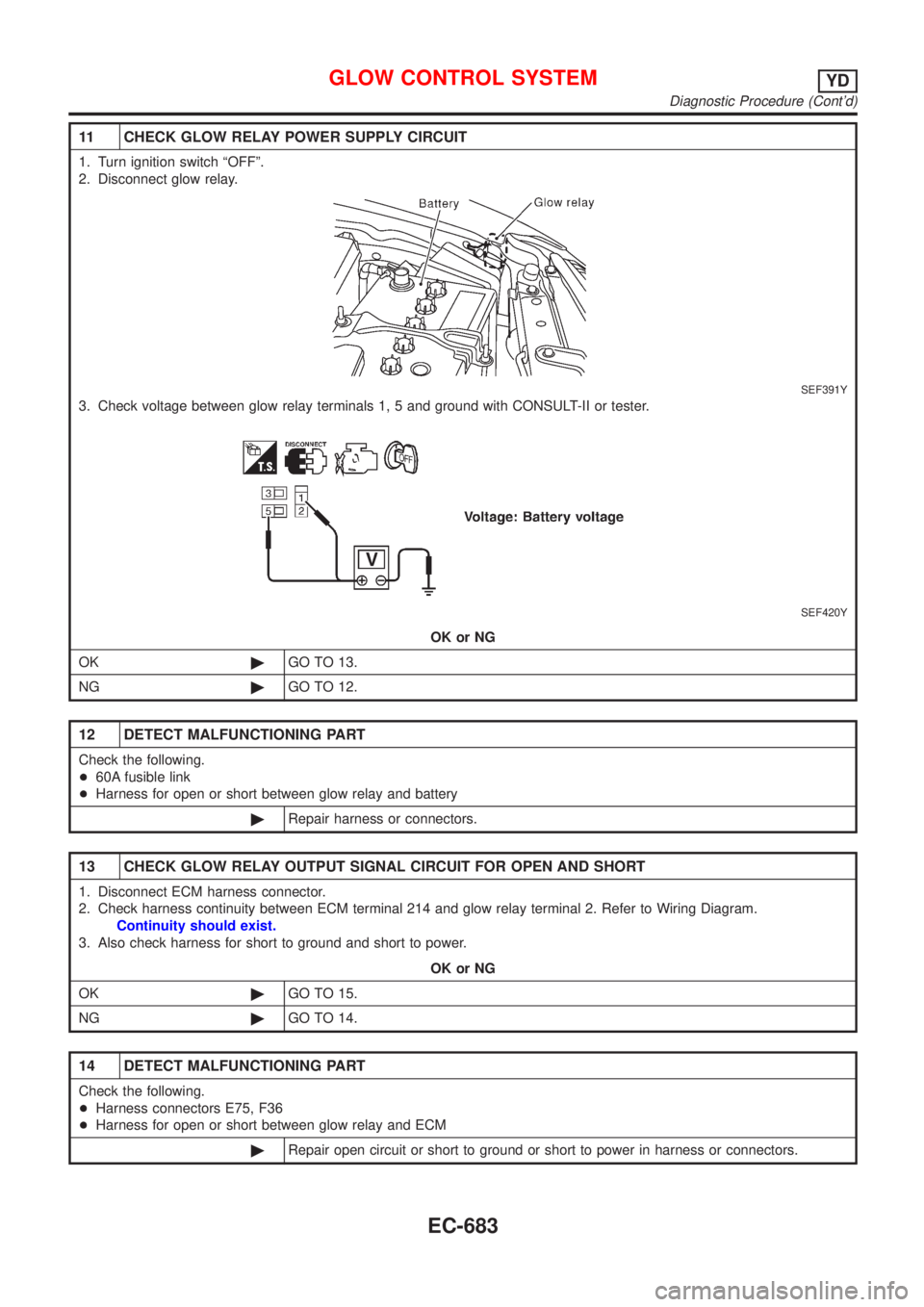
11 CHECK GLOW RELAY POWER SUPPLY CIRCUIT
1. Turn ignition switch ªOFFº.
2. Disconnect glow relay.
SEF391Y
3. Check voltage between glow relay terminals 1, 5 and ground with CONSULT-II or tester.
SEF420Y
OK or NG
OK©GO TO 13.
NG©GO TO 12.
12 DETECT MALFUNCTIONING PART
Check the following.
+60A fusible link
+Harness for open or short between glow relay and battery
©Repair harness or connectors.
13 CHECK GLOW RELAY OUTPUT SIGNAL CIRCUIT FOR OPEN AND SHORT
1. Disconnect ECM harness connector.
2. Check harness continuity between ECM terminal 214 and glow relay terminal 2. Refer to Wiring Diagram.
Continuity should exist.
3. Also check harness for short to ground and short to power.
OK or NG
OK©GO TO 15.
NG©GO TO 14.
14 DETECT MALFUNCTIONING PART
Check the following.
+Harness connectors E75, F36
+Harness for open or short between glow relay and ECM
©Repair open circuit or short to ground or short to power in harness or connectors.
GLOW CONTROL SYSTEMYD
Diagnostic Procedure (Cont'd)
EC-683
Page 982 of 2493

DescriptionNJEC0764SYSTEM DESCRIPTIONNJEC0764S01
Sensor Input Signal to ECM ECM Function Actuator
Electronic controlled fuel injection pump Fuel injection signal
EGR volume con-
trolEGR volume control
valve Crankshaft position sensor (TDC) Engine speed
Vehicle speed sensor Vehicle speed
Engine coolant temperature sensor Engine coolant temperature
Ignition switch Start signal
Accelerator position sensor Accelerator position
Mass air flow sensor Amount of intake air
Air conditioner switch Air conditioner operation
Electrical load Electrical load signal
This system controls flow rate of EGR led from exhaust manifold
to intake manifold. The opening of the EGR by-pass passage in the
EGR volume control valve changes to control the flow rate. A
built-in step motor moves the valve in steps corresponding to the
ECM output pulses. The opening of the valve varies for optimum
engine control. The optimum value stored in the ECM is determined
by considering various engine conditions.
The EGR volume control valve remains close under the following
conditions.
+Engine stopped
+Engine starting
+Low engine coolant temperature
+Excessively high engine coolant temperature
+High engine speed
+Wide open throttle
SEF908Y
SEF411Y
COMPONENT DESCRIPTIONNJEC0764S02EGR Volume Control ValveNJEC0764S0201The EGR volume control valve uses a step motor to control the flow
rate of EGR from exhaust manifold. This motor has four winding
phases. It operates according to the output pulse signal of the
ECM. Two windings are turned ON and OFF in sequence. Each
time an ON pulse is issued, the valve opens or closes, changing
the flow rate. When no change in the flow rate is needed, the ECM
does not issue the pulse signal. A certain voltage signal is issued
so that the valve remains at that particular opening.
EGR VOLUME CONTROL SYSTEMYD
Description
EC-686
Page 985 of 2493
Diagnostic ProcedureNJEC0768
1 CHECK EGR VOLUME CONTROL SYSTEM OVERALL FUNCTION
1. Turn ignition switch ªOFFº.
2. Set the oscilloscope probe between ECM terminals 337, 338, 350, 351 and ground.
3. Start engine and let it idle.
4. Check the oscilloscope screen when revving engine up to 3,200 rpm and return to idle.
SEF247Z
OK or NG
OK©INSPECTION END
NG©GO TO 2.
2 CHECK EGR VOLUME CONTROL VALVE POWER SUPPLY CIRCUIT-I
1. Turn ignition switch ªOFFº.
2. Disconnect EGR volume control valve harness connector.
SEF388Y
3. Turn ignition switch ªONº.
4. Check voltage between EGR volume control valve terminals 2, 5 and ground with CONSULT-II or tester.
SEF412Y
OK or NG
OK©GO TO 7.
NG©GO TO 3.
EGR VOLUME CONTROL SYSTEMYD
Diagnostic Procedure
EC-689