Page 118 of 2493

SEM932C
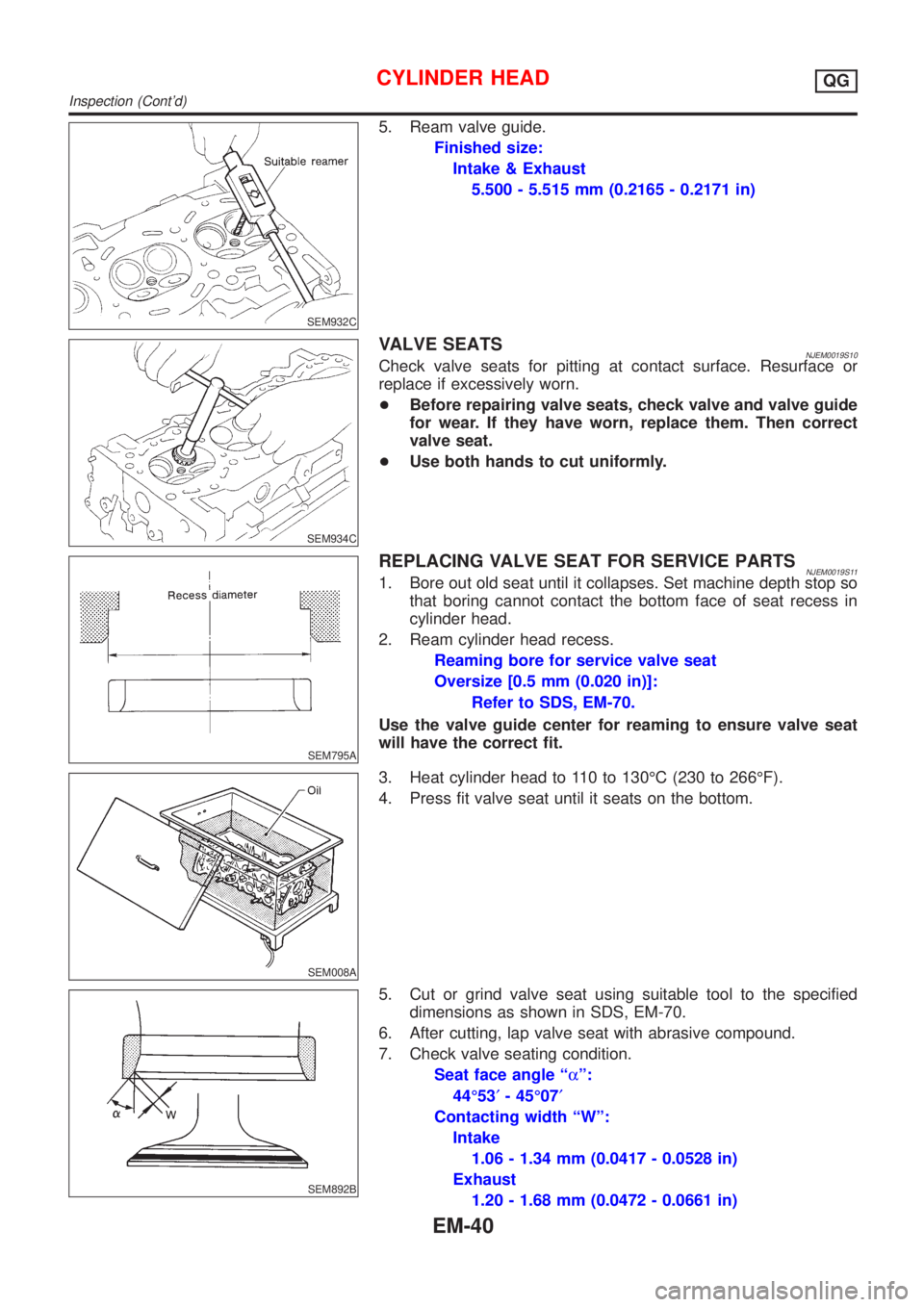
5. Ream valve guide.
Finished size:
Intake & Exhaust
5.500 - 5.515 mm (0.2165 - 0.2171 in)
SEM934C
VALVE SEATSNJEM0019S10Check valve seats for pitting at contact surface. Resurface or
replace if excessively worn.
+Before repairing valve seats, check valve and valve guide
for wear. If they have worn, replace them. Then correct
valve seat.
+Use both hands to cut uniformly.
SEM795A
REPLACING VALVE SEAT FOR SERVICE PARTSNJEM0019S111. Bore out old seat until it collapses. Set machine depth stop so
that boring cannot contact the bottom face of seat recess in
cylinder head.
2. Ream cylinder head recess.
Reaming bore for service valve seat
Oversize [0.5 mm (0.020 in)]:
Refer to SDS, EM-70.
Use the valve guide center for reaming to ensure valve seat
will have the correct fit.
SEM008A
3. Heat cylinder head to 110 to 130ÉC (230 to 266ÉF).
4. Press fit valve seat until it seats on the bottom.
SEM892B
5. Cut or grind valve seat using suitable tool to the specified
dimensions as shown in SDS, EM-70.
6. After cutting, lap valve seat with abrasive compound.
7. Check valve seating condition.
Seat face angle ªaº:
44É53¢- 45É07¢
Contacting width ªWº:
Intake
1.06 - 1.34 mm (0.0417 - 0.0528 in)
Exhaust
1.20 - 1.68 mm (0.0472 - 0.0661 in)
CYLINDER HEADQG
Inspection (Cont'd)
EM-40
Page 134 of 2493

SEM166D
SEM929F
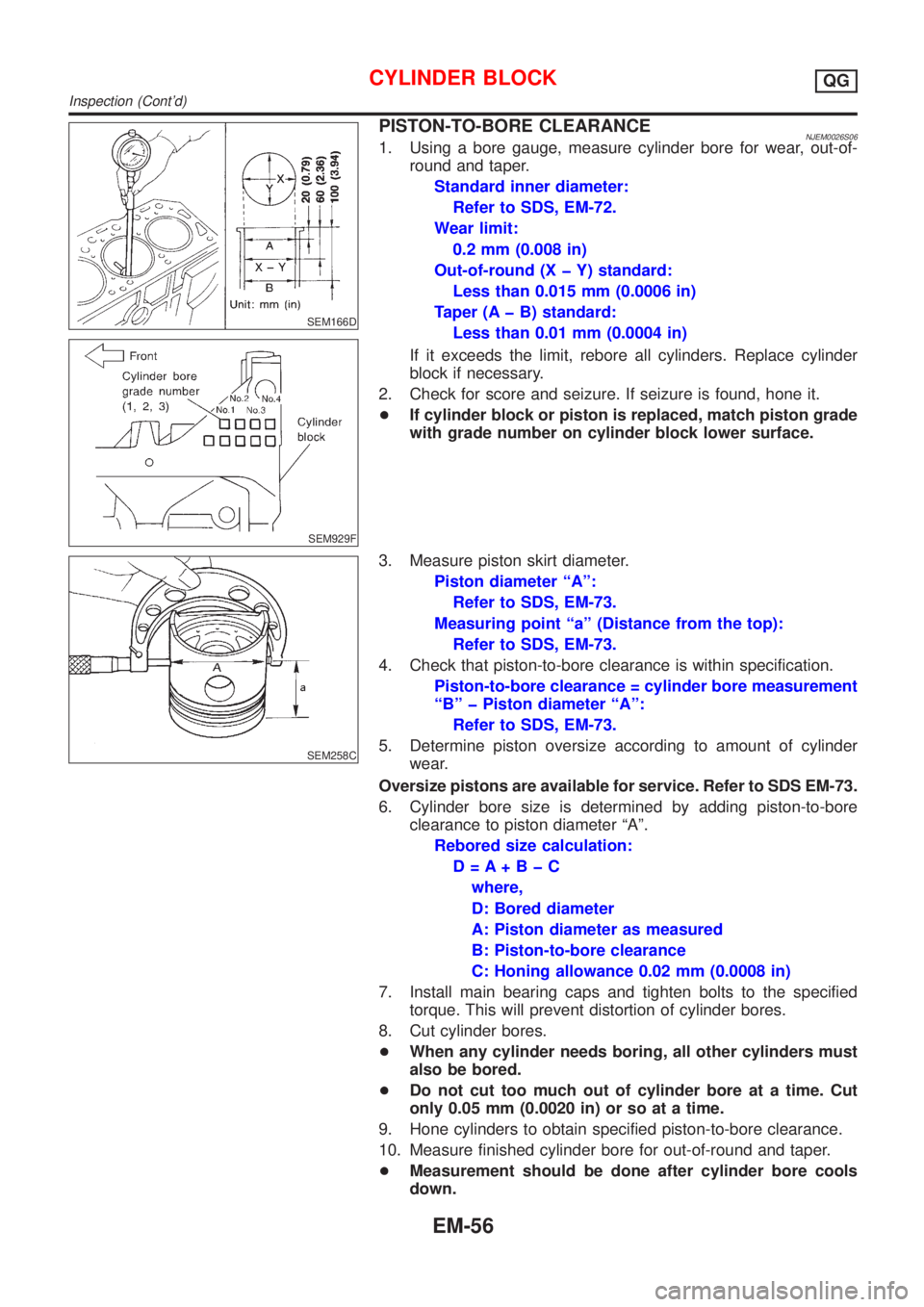
PISTON-TO-BORE CLEARANCENJEM0026S061. Using a bore gauge, measure cylinder bore for wear, out-of-
round and taper.
Standard inner diameter:
Refer to SDS, EM-72.
Wear limit:
0.2 mm (0.008 in)
Out-of-round (X þ Y) standard:
Less than 0.015 mm (0.0006 in)
Taper (A þ B) standard:
Less than 0.01 mm (0.0004 in)
If it exceeds the limit, rebore all cylinders. Replace cylinder
block if necessary.
2. Check for score and seizure. If seizure is found, hone it.
+If cylinder block or piston is replaced, match piston grade
with grade number on cylinder block lower surface.
SEM258C
3. Measure piston skirt diameter.
Piston diameter ªAº:
Refer to SDS, EM-73.
Measuring point ªaº (Distance from the top):
Refer to SDS, EM-73.
4. Check that piston-to-bore clearance is within specification.
Piston-to-bore clearance = cylinder bore measurement
ªBº þ Piston diameter ªAº:
Refer to SDS, EM-73.
5. Determine piston oversize according to amount of cylinder
wear.
Oversize pistons are available for service. Refer to SDS EM-73.
6. Cylinder bore size is determined by adding piston-to-bore
clearance to piston diameter ªAº.
Rebored size calculation:
D=A+BþC
where,
D: Bored diameter
A: Piston diameter as measured
B: Piston-to-bore clearance
C: Honing allowance 0.02 mm (0.0008 in)
7. Install main bearing caps and tighten bolts to the specified
torque. This will prevent distortion of cylinder bores.
8. Cut cylinder bores.
+When any cylinder needs boring, all other cylinders must
also be bored.
+Do not cut too much out of cylinder bore at a time. Cut
only 0.05 mm (0.0020 in) or so at a time.
9. Hone cylinders to obtain specified piston-to-bore clearance.
10. Measure finished cylinder bore for out-of-round and taper.
+Measurement should be done after cylinder bore cools
down.
CYLINDER BLOCKQG
Inspection (Cont'd)
EM-56
Page 142 of 2493

General SpecificationsNJEM0028
EngineQG15DE QG18DE
ClassificationGasoline
Cylinder arrangement4, in-line
Displacement
cm
3(cu in)1,497 (91.35) 1,769 (107.94)
Bore´stroke
mm (in)73.6´88.0 (2.898´3.465) 80.0´88.0 (3.150´3.465)
Valve arrangementDOHC
Firing order1-3-4-2
Number of piston ringsCompression 2
Oil 1
Number of main bearings5
Compression ratio9.5 (9.9*)
*: For QG15DE for Europe
EM120
abcde f
Valve timingQG18DE 222É 236É 0É (20É) 56É (36É) þ2É 44É
QG15DE 222É 222É 0É 42É þ2É 44É
( ): Valve timing control ON
Compression PressureNJEM0029Unit: kPa (bar, kg/cm2, psi)/350 rpm
Standard1,324 (13.24, 13.5, 192)
1,372 (13.720, 13.99, 198.9)*
Minimum1,128 (11.28, 11.5, 164)
1,176 (11.759, 11.99, 170.5)*
Difference limit between cylinders 98 (0.98, 1.0, 14)
*: For QG15DE
Belt DeflectionNJEM0045Unit: mm (in)
Applied engineUsed belt deflection
Deflection of new belt
LimitDeflection after adjust-
ment
AlternatorWith air conditioner
compressorQG15´18DE 8.1 (0.319)5.3 - 5.7
(0.209 - 0.224)4.5 - 5.0
(0.177 - 0.197)
Without air conditioner
compressorQG15´18DE 10.2 (0.402)6.5 - 7.0
(0.256 - 0.276)5.5 - 6.1
(0.217 - 0.240)
SERVICE DATA AND SPECIFICATIONS (SDS)QG
General Specifications
EM-64
Page 143 of 2493
Applied engineUsed belt deflection
Deflection of new belt
LimitDeflection after adjust-
ment
Power steering oil pumpQG15DE 8.5 (0.335)5.2 - 5.8
(0.205 - 0.228)4.6 - 5.2
(0.181 - 0.205)
QG18DE 7.1 (0.280)4.4 - 4.9
(0.173 - 0.193)3.9 - 4.4
(0.154 - 0.173)
Applied pushing force 98 N (10 kg, 22 lb)
Spark PlugNJEM0046
NGK Champion
TypeStandard BKR5E-11 RC10YC4
Hot BKR4E-11 Ð
Cold BKR6E-11 Ð
Plug gap mm (in)1.0 - 1.1 (0.039 - 0.043)
Cylinder HeadNJEM0030Unit: mm (in)
Standard Limit
Head surface flatness Less than 0.03 (0.0012) 0.1 (0.004)
Height 117.8 - 118.0 (4.638 - 4.646) Ð
SERVICE DATA AND SPECIFICATIONS (SDS)QG
Belt Deflection (Cont'd)
EM-65
Page 144 of 2493

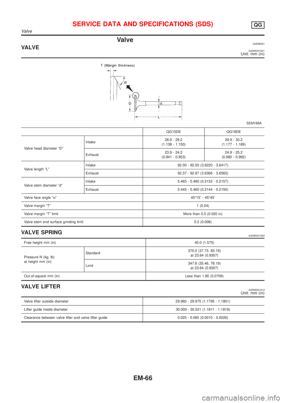
ValveNJEM0031VALVENJEM0031S01Unit: mm (in)
SEM188A
QG15DE QG18DE
Valve head diameter ªDºIntake28.9 - 29.2
(1.138 - 1.150)29.9 - 30.2
(1.177 - 1.189)
Exhaust23.9 - 24.2
(0.941 - 0.953)24.9 - 25.2
(0.980 - 0.992)
Valve length ªLºIntake 92.00 - 92.50 (3.6220 - 3.6417)
Exhaust 92.37 - 92.87 (3.6366 - 3.6563)
Valve stem diameter ªdºIntake 5.465 - 5.480 (0.2152 - 0.2157)
Exhaust 5.445 - 5.460 (0.2144 - 0.2150)
Valve face angle ªaº45É15¢- 45É45¢
Valve margin ªTº1 (0.04)
Valve margin ªTº limitMore than 0.5 (0.020 in)
Valve stem end surface grinding limit 0.2 (0.008)
VALVE SPRINGNJEM0031S02
Free height mm (in)40.0 (1.575)
Pressure N (kg, lb)
at height mm (in)Standard370.0 (37.73, 83.19)
at 23.64 (0.9307)
Limit347.8 (35.46, 78.19)
at 23.64 (0.9307)
Out-of-square mm (in)Less than 1.80 (0.0709)
VALVE LIFTERNJEM0031S10Unit: mm (in)
Valve lifter outside diameter 29.960 - 29.975 (1.1795 - 1.1801)
Lifter guide inside diameter 30.000 - 30.021 (1.1811 - 1.1819)
Clearance between valve lifter and valve lifter guide 0.025 - 0.065 (0.0010 - 0.0026)
SERVICE DATA AND SPECIFICATIONS (SDS)QG
Valve
EM-66
Page 145 of 2493

VALVE CLEARANCE=NJEM0031S11Unit: mm (in)
For adjusting For checking
Hot Cold* (reference data) Hot
Intake 0.32 - 0.40 (0.013 - 0.016) 0.25 - 0.33 (0.010 - 0.013) 0.21 - 0.49 (0.008 - 0.019)
Exhaust 0.37 - 0.45 (0.015 - 0.018) 0.32 - 0.40 (0.013 - 0.016) 0.30 - 0.58 (0.012 - 0.023)
*: At a temperature of approximately 20ÉC (68ÉF)
Whenever valve clearances are adjusted to cold specifications, check that the clearances satisfy hot specifications and adjust
again if necessary.
VALVE GUIDENJEM0031S04Unit: mm (in)
MEM096A
Intake Exhaust
Standard Service Standard Service
Valve guideOuter diameter9.523 - 9.534
(0.3749 - 0.3754)9.723 - 9.734
(0.3828 - 0.3832)9.523 - 9.534
(0.3749 - 0.3754)9.723 - 9.734
(0.3828 - 0.3832)
Inner diameter
[Finished size]5.500 - 5.515 (0.2165 - 0.2171) 5.500 - 5.515 (0.2165 - 0.2171)
Cylinder head valve guide hole diameter9.475 - 9.496
(0.3730 - 0.3739)9.685 - 9.696
(0.3813 - 0.3817)9.475 - 9.496
(0.3730 - 0.3739)9.685 - 9.696
(0.3813 - 0.3817)
Interference fit of valve guide0.027 - 0.059
(0.0011 - 0.0023)0.027 - 0.049
(0.0011 - 0.0019)0.027 - 0.059
(0.0011 - 0.0023)0.027 - 0.049
(0.0011 - 0.0019)
Stem to guide clearance 0.020 - 0.050 (0.0008 - 0.0020) 0.040 - 0.070 (0.0016 - 0.0028)
Valve deflection limit (Dial gauge reading) 0.2 (0.008)
Projection length ªLº 11.5 - 11.7 (0.453 - 0.461)
AVAILABLE SHIMSNJEM0031S07
Thickness mm (in) Identification mark
2.00 (0.0787) 200
2.02 (0.0795) 202
2.04 (0.0803) 204
2.06 (0.0811) 206
2.08 (0.0819) 208
2.10 (0.0827) 210
2.12 (0.0835) 212
2.14 (0.0843) 214
2.16 (0.0850) 216
SERVICE DATA AND SPECIFICATIONS (SDS)QG
Valve (Cont'd)
EM-67
Page 146 of 2493
2.18 (0.0858) 218
2.20 (0.0866) 220
2.21 (0.0870) 221
2.22 (0.0874) 222
2.23 (0.0878) 223
2.24 (0.0882) 224
2.25 (0.0886) 225
2.26 (0.0890) 226
2.27 (0.0895) 227
2.28 (0.0898) 228
2.29 (0.0902) 229
2.30 (0.0906) 230
2.31 (0.0909) 231
2.32 (0.0913) 232
2.33 (0.0917) 233
2.34 (0.0921) 234
2.35 (0.0925) 235
2.36 (0.0929) 236
2.37 (0.0933) 237
2.38 (0.0937) 238
2.39 (0.0941) 239
2.40 (0.0945) 240
2.41 (0.0949) 241
2.42 (0.0953) 242
2.43 (0.0957) 243
2.44 (0.0961) 244
2.45 (0.0965) 245
2.46 (0.0969) 246
2.47 (0.0972) 247
2.48 (0.0976) 248
2.49 (0.0980) 249
2.50 (0.0984) 250
2.51 (0.0988) 251
2.52 (0.0992) 252
2.53 (0.0966) 253
2.54 (0.1000) 254
2.55 (0.1004) 255
2.56 (0.1008) 256
2.57 (0.1012) 257
2.58 (0.1016) 258
2.59 (0.1020) 259
SERVICE DATA AND SPECIFICATIONS (SDS)QG
Valve (Cont'd)
EM-68
Page 147 of 2493
2.60 (0.1024) 260
2.61 (0.1028) 261
2.62 (0.1031) 262
2.63 (0.1035) 263
2.64 (0.1039) 264
2.65 (0.1043) 265
2.66 (0.1047) 266
2.68 (0.1055) 268
2.70 (0.1063) 270
2.72 (0.1071) 272
2.74 (0.1079) 274
2.76 (0.1087) 276
2.78 (0.1094) 278
2.80 (0.1102) 280
2.82 (0.1110) 282
2.84 (0.1118) 284
2.86 (0.1126) 286
2.88 (0.1134) 288
2.90 (0.1142) 290
2.92 (0.1150) 292
2.94 (0.1157) 294
2.96 (0.1165) 296
2.98 (0.1173) 298
SERVICE DATA AND SPECIFICATIONS (SDS)QG
Valve (Cont'd)
EM-69