Page 768 of 2493
Diagnostic Procedure=NJEC0454
1 INSPECTION START
Do you have CONSULT-II?
YesorNo
Ye s©GO TO 2.
No©GO TO 3.
2 CHECK OVERALL FUNCTION
With CONSULT-II
1. Start engine.
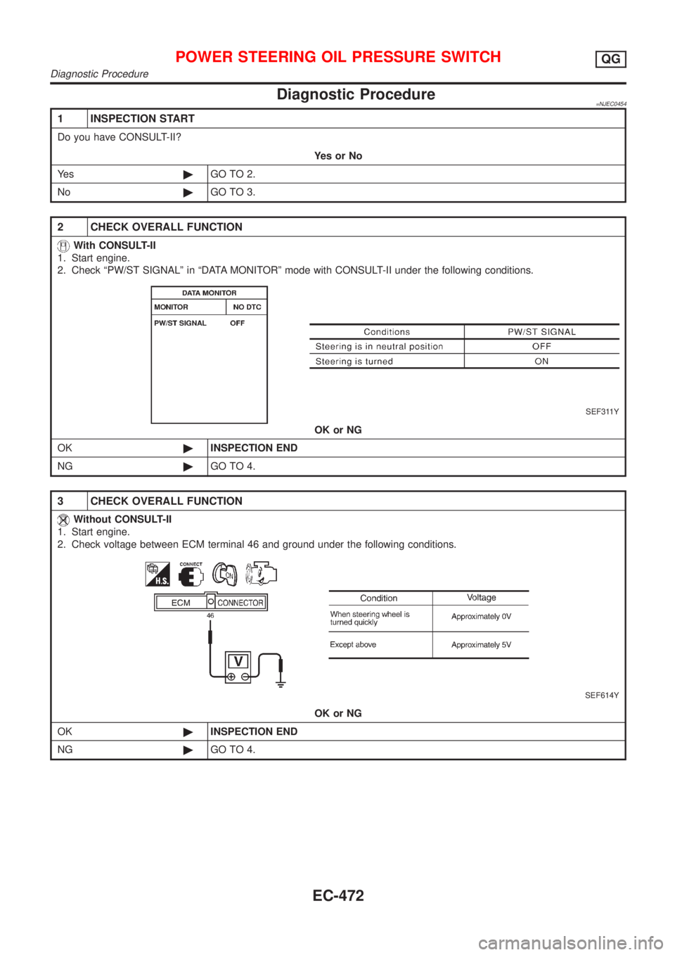
2. Check ªPW/ST SIGNALº in ªDATA MONITORº mode with CONSULT-II under the following conditions.
SEF311Y
OK or NG
OK©INSPECTION END
NG©GO TO 4.
3 CHECK OVERALL FUNCTION
Without CONSULT-II
1. Start engine.
2. Check voltage between ECM terminal 46 and ground under the following conditions.
SEF614Y
OK or NG
OK©INSPECTION END
NG©GO TO 4.
POWER STEERING OIL PRESSURE SWITCHQG
Diagnostic Procedure
EC-472
Page 838 of 2493

SYSTEM Ð Basic engine control
systemSYMPTOM
Reference page
Feature of symptom, Check pointROUGH IDLE/HUNTING
IDLING VIBRATION
SLOW/NO RETURN TO IDLE
OVERHEAT/HIGH ENGINE COOLANT TEMPERATURE
EXCESSIVE FUEL CONSUMPTION
EXCESSIVE OIL CONSUMPTION
ABNORMAL SMOKE COLOR
DEAD BATTERY (UNDER CHARGE)
Malfunction indicator illuminates.
Can be detected by CONSULT-II?BLACK SMOKE
WHITE SMOKEWarranty symptom code AG AH AJ AK AL AM AP HA
Electronic control fuel injection
pump mainframe44345433Ð*1
Injection nozzle 3 3 3 4 3 EC-509 *2
Glow system 1 1 EC-677
Engine body 3 3 3 3 3 3 EM section *3
EGR system 3 EC-686
Air cleaner and ducts 3 3 MA section *4
1 - 5: The numbers refer to the order of inspection.
(continued on next page)
*1: Fuel injection system malfunction or fuel injection timing control system malfunction may be the cause.
*2: Depends on open-valve pressure and spray pattern.
*3: Caused mainly by insufficient compression pressure.
*4: Symptom varies depending on off-position of air duct, etc.
TROUBLE DIAGNOSIS Ð GENERAL DESCRIPTIONYD
Symptom Matrix Chart (Cont'd)
EC-542
Page 1030 of 2493
NJCL0004
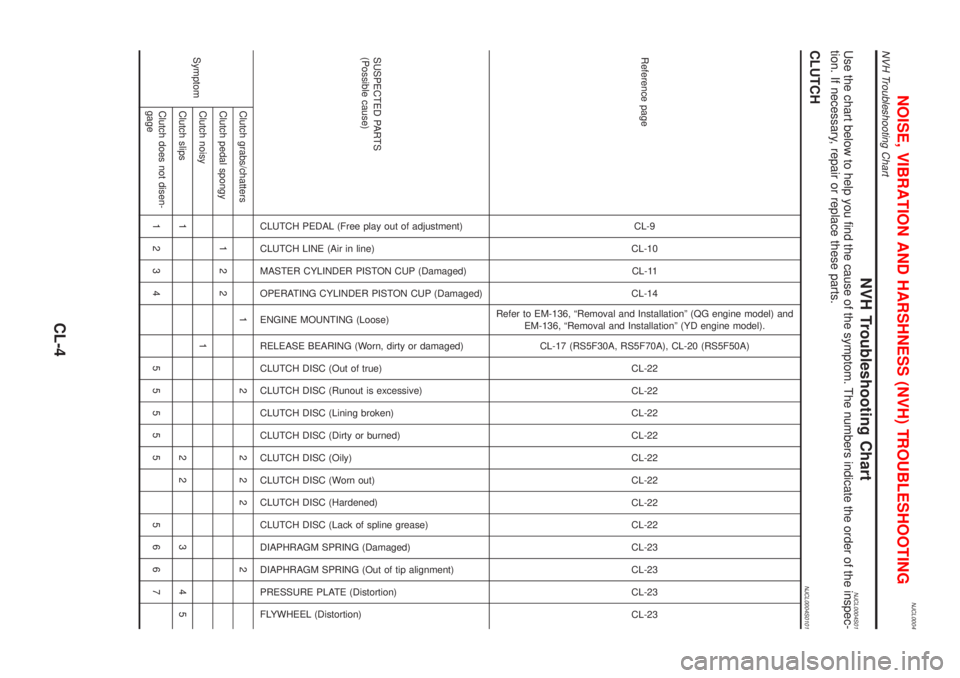
NVH Troubleshooting ChartNJCL0004S01Use the chart below to help you find the cause of the symptom. The numbers indicate the order of the inspec-
tion. If necessary, repair or replace these parts.
CLUTCHNJCL0004S0101
Reference pageCL-9
CL-10
CL-11
CL-14
Refer to EM-136, ªRemoval and Installationº (QG engine model) and
EM-136, ªRemoval and Installationº (YD engine model).
CL-17 (RS5F30A, RS5F70A), CL-20 (RS5F50A)
CL-22
CL-22
CL-22
CL-22
CL-22
CL-22
CL-22
CL-22
CL-23
CL-23
CL-23
CL-23
SUSPECTED PARTS
(Possible cause)
CLUTCH PEDAL (Free play out of adjustment)
CLUTCH LINE (Air in line)
MASTER CYLINDER PISTON CUP (Damaged)
OPERATING CYLINDER PISTON CUP (Damaged)
ENGINE MOUNTING (Loose)
RELEASE BEARING (Worn, dirty or damaged)
CLUTCH DISC (Out of true)
CLUTCH DISC (Runout is excessive)
CLUTCH DISC (Lining broken)
CLUTCH DISC (Dirty or burned)
CLUTCH DISC (Oily)
CLUTCH DISC (Worn out)
CLUTCH DISC (Hardened)
CLUTCH DISC (Lack of spline grease)
DIAPHRAGM SPRING (Damaged)
DIAPHRAGM SPRING (Out of tip alignment)
PRESSURE PLATE (Distortion)
FLYWHEEL (Distortion)
SymptomClutch grabs/chatters 1 2 2 2 2 2
Clutch pedal spongy 1 2 2
Clutch noisy 1
Clutch slips 1 2 2 3 4 5
Clutch does not disen-
gage1234 55555 5667
NOISE, VIBRATION AND HARSHNESS (NVH) TROUBLESHOOTING
NVH Troubleshooting Chart
CL-4
Page 1046 of 2493
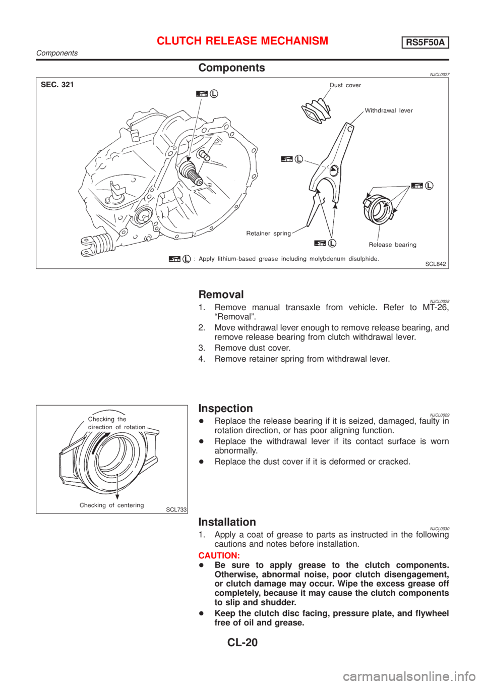
ComponentsNJCL0027
SCL842
RemovalNJCL00281. Remove manual transaxle from vehicle. Refer to MT-26,
ªRemovalº.
2. Move withdrawal lever enough to remove release bearing, and
remove release bearing from clutch withdrawal lever.
3. Remove dust cover.
4. Remove retainer spring from withdrawal lever.
SCL733
InspectionNJCL0029+Replace the release bearing if it is seized, damaged, faulty in
rotation direction, or has poor aligning function.
+Replace the withdrawal lever if its contact surface is worn
abnormally.
+Replace the dust cover if it is deformed or cracked.
InstallationNJCL00301. Apply a coat of grease to parts as instructed in the following
cautions and notes before installation.
CAUTION:
+Be sure to apply grease to the clutch components.
Otherwise, abnormal noise, poor clutch disengagement,
or clutch damage may occur. Wipe the excess grease off
completely, because it may cause the clutch components
to slip and shudder.
+Keep the clutch disc facing, pressure plate, and flywheel
free of oil and grease.
CLUTCH RELEASE MECHANISMRS5F50A
Components
CL-20
Page 1207 of 2493
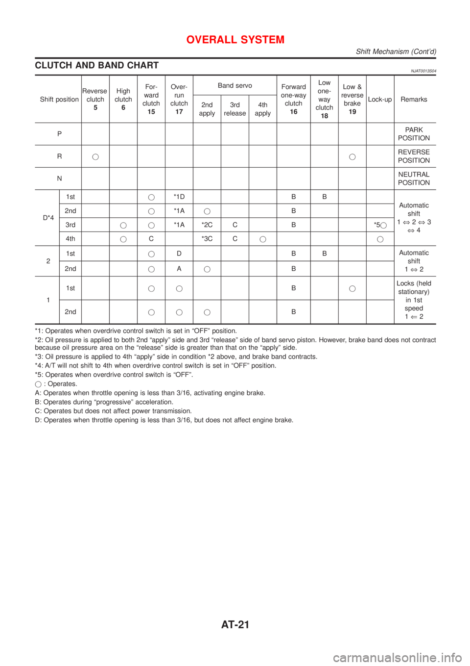
CLUTCH AND BAND CHARTNJAT0013S04
Shift positionReverse
clutch
5High
clutch
6For-
ward
clutch
15Over-
run
clutch
17Band servo
Forward
one-way
clutch
16Low
one-
way
clutch
18Low &
reverse
brake
19Lock-up Remarks
2nd
apply3rd
release4th
apply
PPARK
POSITION
RjjREVERSE
POSITION
NNEUTRAL
POSITION
D*41stj*1D B B
Automatic
shift
1Û2Û3
Û4 2ndj*1AjB
3rdjj*1A *2C C B *5j
4thjC *3C Cjj
21stjDBBAutomatic
shift
1Û2 2ndjAjB
11stjjBjLocks (held
stationary)
in 1st
speed
1Ü2 2ndjjjB
*1: Operates when overdrive control switch is set in ªOFFº position.
*2: Oil pressure is applied to both 2nd ªapplyº side and 3rd ªreleaseº side of band servo piston. However, brake band does not contract
because oil pressure area on the ªreleaseº side is greater than that on the ªapplyº side.
*3: Oil pressure is applied to 4th ªapplyº side in condition *2 above, and brake band contracts.
*4: A/T will not shift to 4th when overdrive control switch is set in ªOFFº position.
*5: Operates when overdrive control switch is ªOFFº.
j: Operates.
A: Operates when throttle opening is less than 3/16, activating engine brake.
B: Operates during ªprogressiveº acceleration.
C: Operates but does not affect power transmission.
D: Operates when throttle opening is less than 3/16, but does not affect engine brake.
OVERALL SYSTEM
Shift Mechanism (Cont'd)
AT-21
Page 1222 of 2493
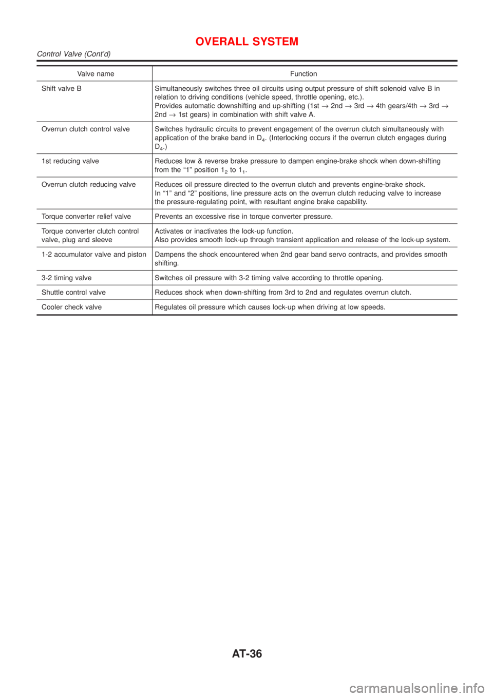
Valve name Function
Shift valve B Simultaneously switches three oil circuits using output pressure of shift solenoid valve B in
relation to driving conditions (vehicle speed, throttle opening, etc.).
Provides automatic downshifting and up-shifting (1st®2nd®3rd®4th gears/4th®3rd®
2nd®1st gears) in combination with shift valve A.
Overrun clutch control valve Switches hydraulic circuits to prevent engagement of the overrun clutch simultaneously with
application of the brake band in D
4. (Interlocking occurs if the overrun clutch engages during
D
4.)
1st reducing valve Reduces low & reverse brake pressure to dampen engine-brake shock when down-shifting
from the ª1º position 1
2to 11.
Overrun clutch reducing valve Reduces oil pressure directed to the overrun clutch and prevents engine-brake shock.
In ª1º and ª2º positions, line pressure acts on the overrun clutch reducing valve to increase
the pressure-regulating point, with resultant engine brake capability.
Torque converter relief valve Prevents an excessive rise in torque converter pressure.
Torque converter clutch control
valve, plug and sleeveActivates or inactivates the lock-up function.
Also provides smooth lock-up through transient application and release of the lock-up system.
1-2 accumulator valve and piston Dampens the shock encountered when 2nd gear band servo contracts, and provides smooth
shifting.
3-2 timing valve Switches oil pressure with 3-2 timing valve according to throttle opening.
Shuttle control valve Reduces shock when down-shifting from 3rd to 2nd and regulates overrun clutch.
Cooler check valve Regulates oil pressure which causes lock-up when driving at low speeds.
OVERALL SYSTEM
Control Valve (Cont'd)
AT-36
Page 1268 of 2493
SAT561J
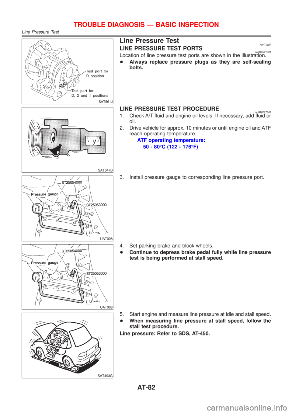
Line Pressure TestNJAT0027LINE PRESSURE TEST PORTSNJAT0027S01Location of line pressure test ports are shown in the illustration.
+Always replace pressure plugs as they are self-sealing
bolts.
SAT647B
LINE PRESSURE TEST PROCEDURENJAT0027S021. Check A/T fluid and engine oil levels. If necessary, add fluid or
oil.
2. Drive vehicle for approx. 10 minutes or until engine oil and ATF
reach operating temperature.
ATF operating temperature:
50 - 80ÉC (122 - 176ÉF)
UAT008
3. Install pressure gauge to corresponding line pressure port.
UAT008
4. Set parking brake and block wheels.
+Continue to depress brake pedal fully while line pressure
test is being performed at stall speed.
SAT493G
5. Start engine and measure line pressure at idle and stall speed.
+When measuring line pressure at stall speed, follow the
stall test procedure.
Line pressure: Refer to SDS, AT-450.
TROUBLE DIAGNOSIS Ð BASIC INSPECTION
Line Pressure Test
AT-82
Page 1269 of 2493
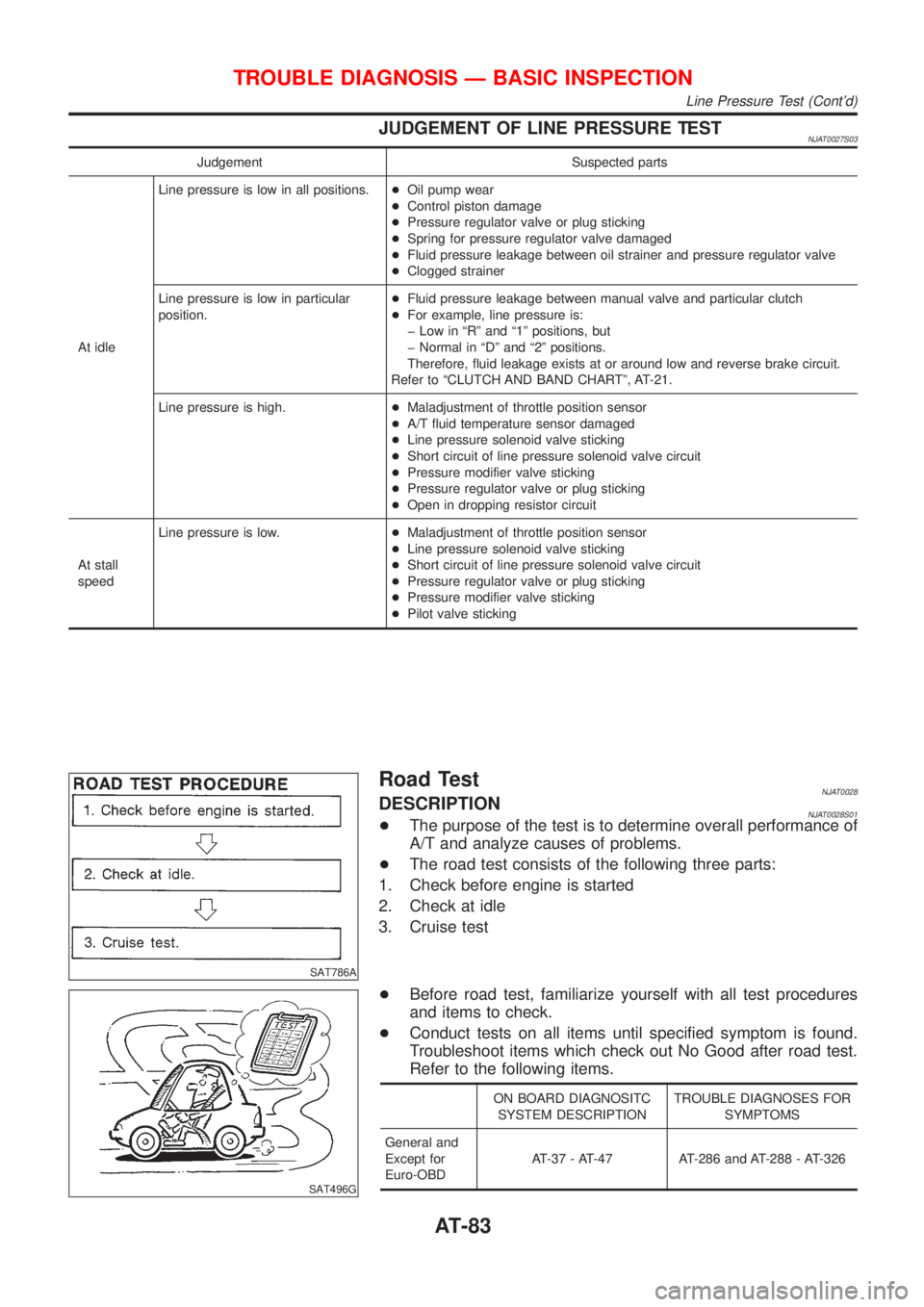
JUDGEMENT OF LINE PRESSURE TESTNJAT0027S03
Judgement Suspected parts
At idleLine pressure is low in all positions.+Oil pump wear
+Control piston damage
+Pressure regulator valve or plug sticking
+Spring for pressure regulator valve damaged
+Fluid pressure leakage between oil strainer and pressure regulator valve
+Clogged strainer
Line pressure is low in particular
position.+Fluid pressure leakage between manual valve and particular clutch
+For example, line pressure is:
þ Low in ªRº and ª1º positions, but
þ Normal in ªDº and ª2º positions.
Therefore, fluid leakage exists at or around low and reverse brake circuit.
Refer to ªCLUTCH AND BAND CHARTº, AT-21.
Line pressure is high.+Maladjustment of throttle position sensor
+A/T fluid temperature sensor damaged
+Line pressure solenoid valve sticking
+Short circuit of line pressure solenoid valve circuit
+Pressure modifier valve sticking
+Pressure regulator valve or plug sticking
+Open in dropping resistor circuit
At stall
speedLine pressure is low.+Maladjustment of throttle position sensor
+Line pressure solenoid valve sticking
+Short circuit of line pressure solenoid valve circuit
+Pressure regulator valve or plug sticking
+Pressure modifier valve sticking
+Pilot valve sticking
SAT786A
Road TestNJAT0028DESCRIPTIONNJAT0028S01+The purpose of the test is to determine overall performance of
A/T and analyze causes of problems.
+The road test consists of the following three parts:
1. Check before engine is started
2. Check at idle
3. Cruise test
SAT496G
+Before road test, familiarize yourself with all test procedures
and items to check.
+Conduct tests on all items until specified symptom is found.
Troubleshoot items which check out No Good after road test.
Refer to the following items.
ON BOARD DIAGNOSITC
SYSTEM DESCRIPTIONTROUBLE DIAGNOSES FOR
SYMPTOMS
General and
Except for
Euro-OBDAT-37 - AT-47 AT-286 and AT-288 - AT-326
TROUBLE DIAGNOSIS Ð BASIC INSPECTION
Line Pressure Test (Cont'd)
AT-83