2001 NISSAN ALMERA N16 ignition
[x] Cancel search: ignitionPage 785 of 2493
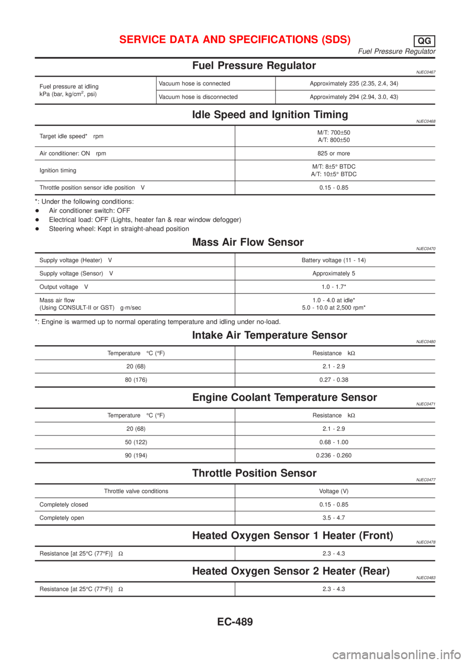
Fuel Pressure RegulatorNJEC0467
Fuel pressure at idling
kPa (bar, kg/cm2, psi)Vacuum hose is connected Approximately 235 (2.35, 2.4, 34)
Vacuum hose is disconnected Approximately 294 (2.94, 3.0, 43)
Idle Speed and Ignition TimingNJEC0468
Target idle speed* rpmM/T: 700±50
A/T: 800±50
Air conditioner: ON rpm825 or more
Ignition timingM/T: 8±5É BTDC
A/T: 10±5É BTDC
Throttle position sensor idle position V 0.15 - 0.85
*: Under the following conditions:
+Air conditioner switch: OFF
+Electrical load: OFF (Lights, heater fan & rear window defogger)
+Steering wheel: Kept in straight-ahead position
Mass Air Flow SensorNJEC0470
Supply voltage (Heater) VBattery voltage (11 - 14)
Supply voltage (Sensor) VApproximately 5
Output voltage V1.0 - 1.7*
Mass air flow
(Using CONSULT-II or GST) g´m/sec1.0 - 4.0 at idle*
5.0 - 10.0 at 2,500 rpm*
*: Engine is warmed up to normal operating temperature and idling under no-load.
Intake Air Temperature SensorNJEC0480
Temperature ÉC (ÉF) Resistance kW
20 (68) 2.1 - 2.9
80 (176) 0.27 - 0.38
Engine Coolant Temperature SensorNJEC0471
Temperature ÉC (ÉF) Resistance kW
20 (68) 2.1 - 2.9
50 (122) 0.68 - 1.00
90 (194) 0.236 - 0.260
Throttle Position SensorNJEC0477
Throttle valve conditions Voltage (V)
Completely closed0.15 - 0.85
Completely open3.5 - 4.7
Heated Oxygen Sensor 1 Heater (Front)NJEC0478
Resistance [at 25ÉC (77ÉF)]W2.3 - 4.3
Heated Oxygen Sensor 2 Heater (Rear)NJEC0483
Resistance [at 25ÉC (77ÉF)]W2.3 - 4.3
SERVICE DATA AND SPECIFICATIONS (SDS)QG
Fuel Pressure Regulator
EC-489
Page 786 of 2493
![NISSAN ALMERA N16 2001 Electronic Repair Manual EGR Volume Control Valve (Where Fitted)NJEC0560
Terminal No. ResistanceW[at 20ÉC (68ÉF)]
1-2
20-24 2-3
4-5
5-6
EGR Temperature Sensor (Where Fitted)NJEC0472
EGR temperature
ÉC (ÉF)Voltage
VResista NISSAN ALMERA N16 2001 Electronic Repair Manual EGR Volume Control Valve (Where Fitted)NJEC0560
Terminal No. ResistanceW[at 20ÉC (68ÉF)]
1-2
20-24 2-3
4-5
5-6
EGR Temperature Sensor (Where Fitted)NJEC0472
EGR temperature
ÉC (ÉF)Voltage
VResista](/manual-img/5/57351/w960_57351-785.png)
EGR Volume Control Valve (Where Fitted)NJEC0560
Terminal No. ResistanceW[at 20ÉC (68ÉF)]
1-2
20-24 2-3
4-5
5-6
EGR Temperature Sensor (Where Fitted)NJEC0472
EGR temperature
ÉC (ÉF)Voltage
VResistance
MW
0 (32) 4.56 0.62 - 1.05
50 (122) 2.25 0.065 - 0.094
100 (212) 0.59 0.011 - 0.015
EVAP Canister Purge Volume Control ValveNJEC0481
Resistance [at 20ÉC (68ÉF)]W31-35
IACV-AAC ValveNJEC0474
Terminal No. ResistanceW[at 20ÉC (68ÉF)]
1-2
20-24 2-3
4-5
5-6
InjectorNJEC0475
Resistance [at 25ÉC (77ÉF)]W13.5 - 17.5
Ignition Coil with Power TransistorNJEC0561
Terminal No. (Polarity) ResistanceW[at 25ÉC (77ÉF)]
3 (+) - 2 (þ) Except 0 or¥
1 (+) - 3 (þ)
Except 0
1 (+) - 2 (þ)
CondenserNJEC0587
Resistance [at 25ÉC (77ÉF)] MWAbove 1
Fuel PumpNJEC0473
Resistance [at 25ÉC (77ÉF)]W0.2 - 5.0
SERVICE DATA AND SPECIFICATIONS (SDS)QG
EGR Volume Control Valve (Where Fitted)
EC-490
Page 792 of 2493

SEF289H
PrecautionsNJEC0603+Before connecting or disconnecting the ECM harness
connector, turn ignition switch OFF and disconnect nega-
tive battery terminal. Failure to do so may damage the
ECM because battery voltage is applied to ECM even if
ignition switch is turned off.
SEF881Y
+When connecting ECM harness connectors, push in both
sides of the connector until you hear a click. Maneuver the
lever until you hear the three connectors on the inside
click. Refer to the figure at left.
SEF291H
+When connecting or disconnecting pin connectors into or
from ECM, take care not to damage pin terminals (bend or
break).
Make sure that there are not any bends or breaks on ECM
pin terminal, when connecting pin connectors.
MEF040D
+Before replacing ECM, perform Terminals and Reference
Value inspection and make sure ECM functions properly.
Refer to EC-554.
SAT652J
+If MI illuminates or blinks irregularly when engine is
running, water may have accumulated in fuel filter. Drain
water from fuel filter. If this does not correct the problem,
perform specified trouble diagnostic procedures.
+After performing each TROUBLE DIAGNOSIS, perform
ªDTC Confirmation Procedureº or ªOverall Function
Checkº.
The DTC should not be displayed in the ª DTC Confirma-
tion Procedureº if the repair is completed. The ªOverall
Function Checkº should be a good result if the repair is
completed.
PRECAUTIONSYD
Precautions
EC-496
Page 800 of 2493
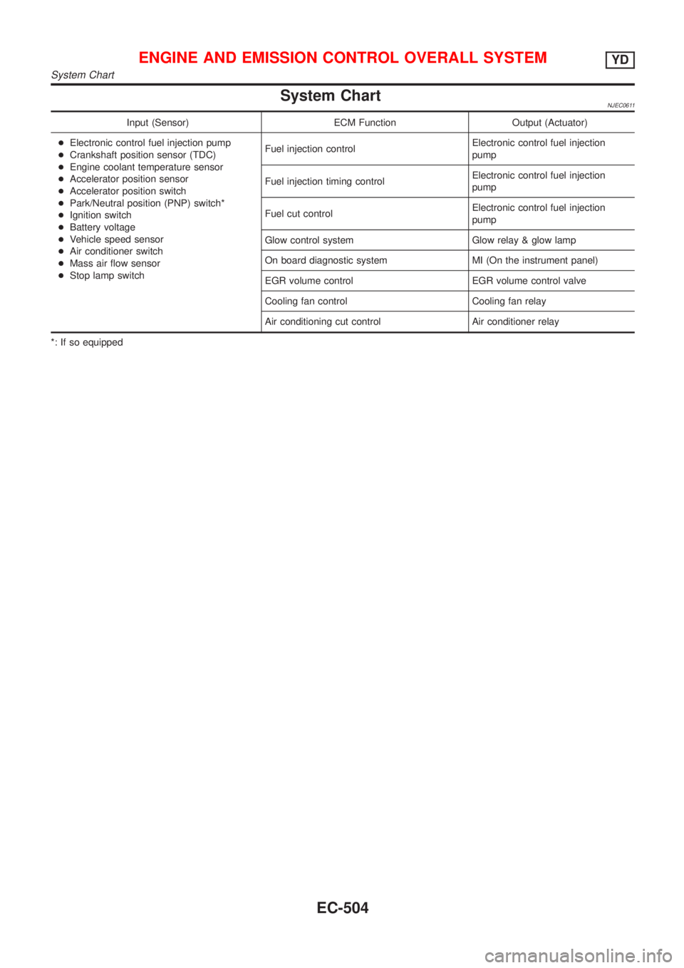
System ChartNJEC0611
Input (Sensor) ECM Function Output (Actuator)
+Electronic control fuel injection pump
+Crankshaft position sensor (TDC)
+Engine coolant temperature sensor
+Accelerator position sensor
+Accelerator position switch
+Park/Neutral position (PNP) switch*
+Ignition switch
+Battery voltage
+Vehicle speed sensor
+Air conditioner switch
+Mass air flow sensor
+Stop lamp switchFuel injection controlElectronic control fuel injection
pump
Fuel injection timing controlElectronic control fuel injection
pump
Fuel cut controlElectronic control fuel injection
pump
Glow control system Glow relay & glow lamp
On board diagnostic system MI (On the instrument panel)
EGR volume control EGR volume control valve
Cooling fan control Cooling fan relay
Air conditioning cut control Air conditioner relay
*: If so equipped
ENGINE AND EMISSION CONTROL OVERALL SYSTEMYD
System Chart
EC-504
Page 801 of 2493
Fuel Injection Control System
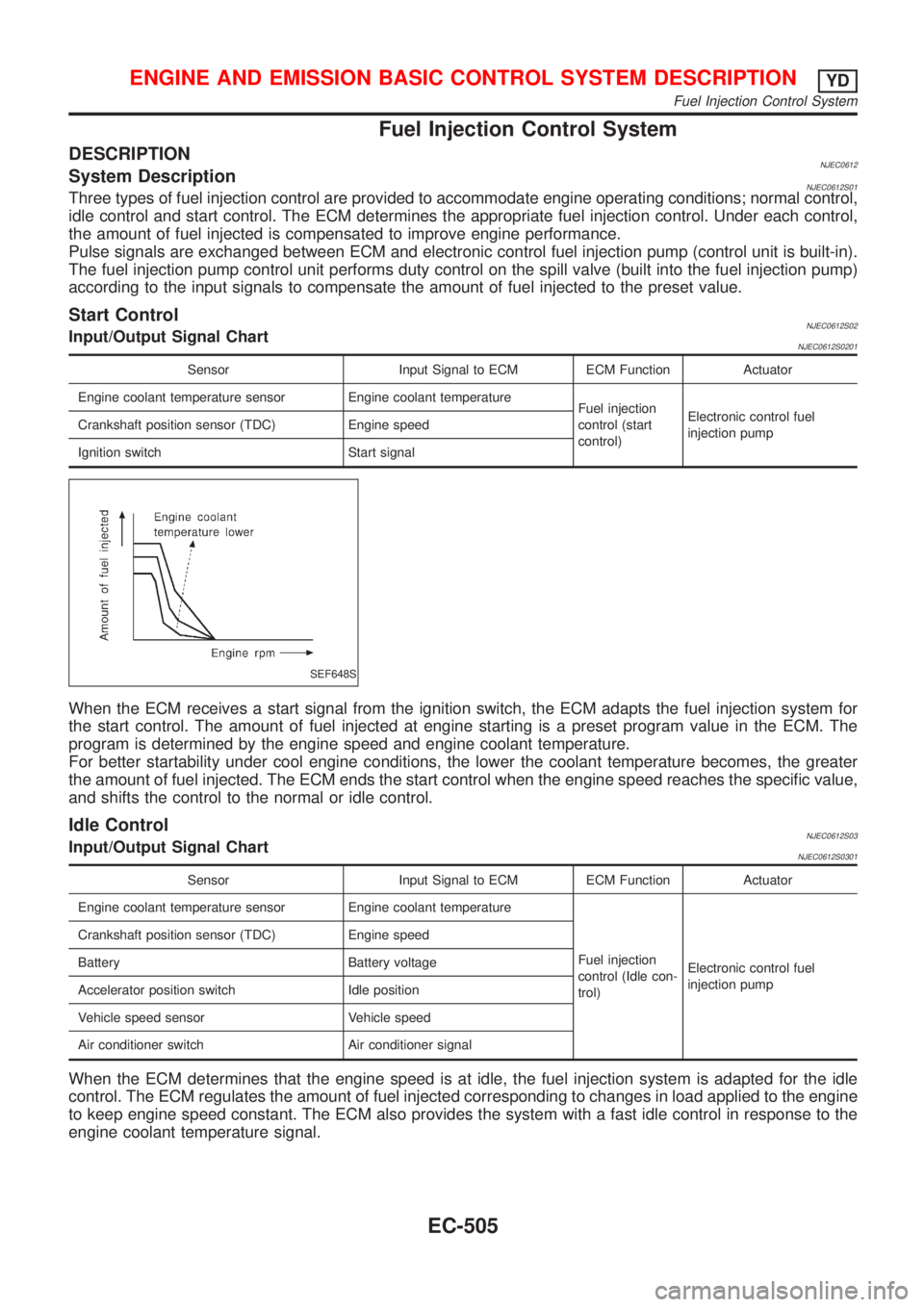
DESCRIPTIONNJEC0612System DescriptionNJEC0612S01Three types of fuel injection control are provided to accommodate engine operating conditions; normal control,
idle control and start control. The ECM determines the appropriate fuel injection control. Under each control,
the amount of fuel injected is compensated to improve engine performance.
Pulse signals are exchanged between ECM and electronic control fuel injection pump (control unit is built-in).
The fuel injection pump control unit performs duty control on the spill valve (built into the fuel injection pump)
according to the input signals to compensate the amount of fuel injected to the preset value.
Start ControlNJEC0612S02Input/Output Signal ChartNJEC0612S0201
Sensor Input Signal to ECM ECM Function Actuator
Engine coolant temperature sensor Engine coolant temperature
Fuel injection
control (start
control)Electronic control fuel
injection pump Crankshaft position sensor (TDC) Engine speed
Ignition switch Start signal
SEF648S
When the ECM receives a start signal from the ignition switch, the ECM adapts the fuel injection system for
the start control. The amount of fuel injected at engine starting is a preset program value in the ECM. The
program is determined by the engine speed and engine coolant temperature.
For better startability under cool engine conditions, the lower the coolant temperature becomes, the greater
the amount of fuel injected. The ECM ends the start control when the engine speed reaches the specific value,
and shifts the control to the normal or idle control.
Idle ControlNJEC0612S03Input/Output Signal ChartNJEC0612S0301
Sensor Input Signal to ECM ECM Function Actuator
Engine coolant temperature sensor Engine coolant temperature
Fuel injection
control (Idle con-
trol)Electronic control fuel
injection pump Crankshaft position sensor (TDC) Engine speed
Battery Battery voltage
Accelerator position switch Idle position
Vehicle speed sensor Vehicle speed
Air conditioner switch Air conditioner signal
When the ECM determines that the engine speed is at idle, the fuel injection system is adapted for the idle
control. The ECM regulates the amount of fuel injected corresponding to changes in load applied to the engine
to keep engine speed constant. The ECM also provides the system with a fast idle control in response to the
engine coolant temperature signal.
ENGINE AND EMISSION BASIC CONTROL SYSTEM DESCRIPTIONYD
Fuel Injection Control System
EC-505
Page 818 of 2493
DTC and MI Detection LogicNJEC0626When a malfunction is detected, the malfunction (DTC) is stored in the ECM memory.
The MI will light up each time the ECM detects malfunction. For diagnostic items causing the MI to light up,
refer to ªTROUBLE DIAGNOSIS Ð INDEXº, EC-492.
Diagnostic Trouble Code (DTC)NJEC0627HOW TO READ DTCNJEC0627S01The DTC can be read by the following methods.
Without CONSULT-II
ECM displays the DTC by a set of four digit numbers with MI illumination in the diagnostic test mode II (Self-
diagnostic results). Example: 0103, 0807, 1002, etc.
With CONSULT-II
CONSULT-II displays the DTC in ªSELF-DIAG RESULTSº mode. Examples: P0115, P0571, P1202, etc.
These DTCs are prescribed by ISO15031-6.
(CONSULT-II also displays the malfunctioning component or system.)
+Output of the trouble code means that the indicated circuit has a malfunction. However, in the Mode
II it does not indicate whether the malfunction is still occurring or occurred in the past and returned
to normal.
CONSULT-II can identify them. Therefore, using CONSULT-II (if available) is recommended.
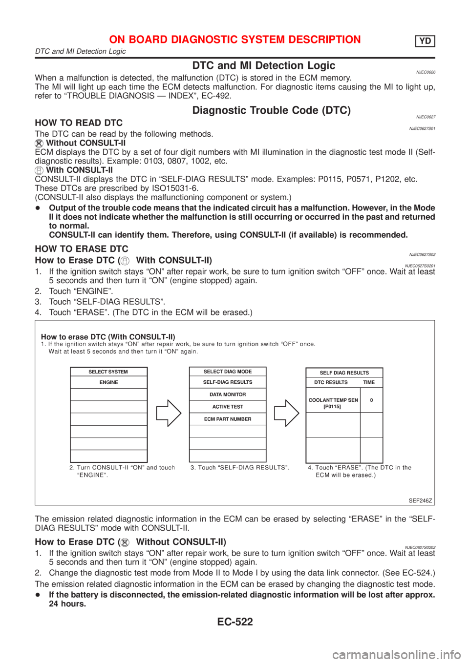
HOW TO ERASE DTCNJEC0627S02How to Erase DTC (With CONSULT-II)NJEC0627S02011. If the ignition switch stays ªONº after repair work, be sure to turn ignition switch ªOFFº once. Wait at least
5 seconds and then turn it ªONº (engine stopped) again.
2. Touch ªENGINEº.
3. Touch ªSELF-DIAG RESULTSº.
4. Touch ªERASEº. (The DTC in the ECM will be erased.)
SEF246Z
The emission related diagnostic information in the ECM can be erased by selecting ªERASEº in the ªSELF-
DIAG RESULTSº mode with CONSULT-II.
How to Erase DTC (Without CONSULT-II)NJEC0627S02021. If the ignition switch stays ªONº after repair work, be sure to turn ignition switch ªOFFº once. Wait at least
5 seconds and then turn it ªONº (engine stopped) again.
2. Change the diagnostic test mode from Mode II to Mode I by using the data link connector. (See EC-524.)
The emission related diagnostic information in the ECM can be erased by changing the diagnostic test mode.
+If the battery is disconnected, the emission-related diagnostic information will be lost after approx.
24 hours.
ON BOARD DIAGNOSTIC SYSTEM DESCRIPTIONYD
DTC and MI Detection Logic
EC-522
Page 819 of 2493
+Erasing the emission-related diagnostic information using CONSULT-II is easier and quicker than
switching the diagnostic test mode using the data link connector.
Malfunction Indicator (MI)
DESCRIPTIONNJEC0628
SAT652J
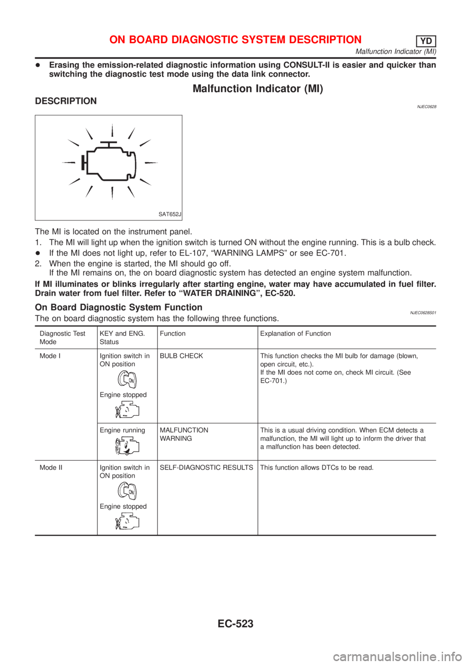
The MI is located on the instrument panel.
1. The MI will light up when the ignition switch is turned ON without the engine running. This is a bulb check.
+If the MI does not light up, refer to EL-107, ªWARNING LAMPSº or see EC-701.
2. When the engine is started, the MI should go off.
If the MI remains on, the on board diagnostic system has detected an engine system malfunction.
If MI illuminates or blinks irregularly after starting engine, water may have accumulated in fuel filter.
Drain water from fuel filter. Refer to ªWATER DRAININGº, EC-520.
On Board Diagnostic System FunctionNJEC0628S01The on board diagnostic system has the following three functions.
Diagnostic Test
ModeKEY and ENG.
StatusFunction Explanation of Function
Mode I Ignition switch in
ON position
Engine stopped
BULB CHECK This function checks the MI bulb for damage (blown,
open circuit, etc.).
If the MI does not come on, check MI circuit. (See
EC-701.)
Engine running
MALFUNCTION
WARNINGThis is a usual driving condition. When ECM detects a
malfunction, the MI will light up to inform the driver that
a malfunction has been detected.
Mode II Ignition switch in
ON position
Engine stopped
SELF-DIAGNOSTIC RESULTS This function allows DTCs to be read.
ON BOARD DIAGNOSTIC SYSTEM DESCRIPTIONYD
Malfunction Indicator (MI)
EC-523
Page 823 of 2493
SEF378Y
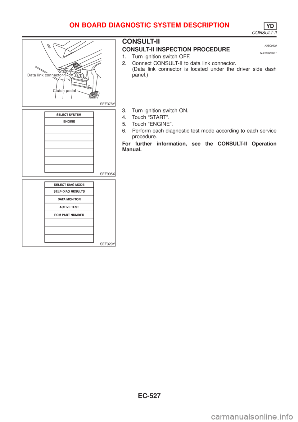
CONSULT-IINJEC0629CONSULT-II INSPECTION PROCEDURENJEC0629S011. Turn ignition switch OFF.
2. Connect CONSULT-II to data link connector.
(Data link connector is located under the driver side dash
panel.)
SEF995X
SEF320Y
3. Turn ignition switch ON.
4. Touch ªSTARTº.
5. Touch ªENGINEº.
6. Perform each diagnostic test mode according to each service
procedure.
For further information, see the CONSULT-II Operation
Manual.
ON BOARD DIAGNOSTIC SYSTEM DESCRIPTIONYD
CONSULT-II
EC-527