Page 1734 of 2493
+It is not necessary to remove connecting bolt except for
disassembly or replacement of caliper assembly. In this
case, suspend cylinder body with wire so as not to stretch
brake hose.
+Burnish the brake contact surfaces after refinishing or
replacing drums or rotors, after replacing pads or linings,
or if a soft pedal occurs at very low mileage.
Refer to ªBrake Burnishing Procedureº, ªON-VEHICLE
SERVICEº, BR-7.
SBR764E
SBR916C
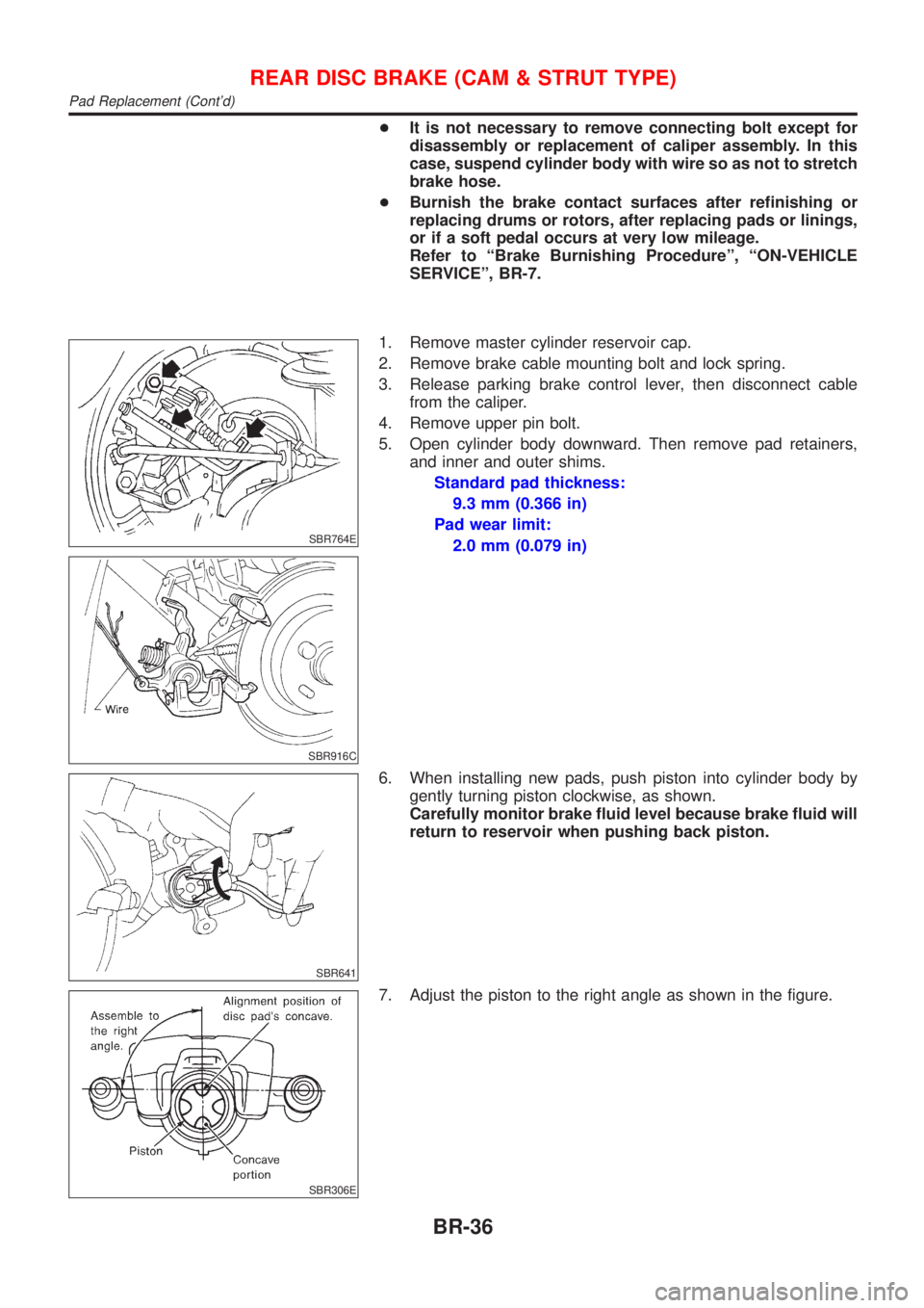
1. Remove master cylinder reservoir cap.
2. Remove brake cable mounting bolt and lock spring.
3. Release parking brake control lever, then disconnect cable
from the caliper.
4. Remove upper pin bolt.
5. Open cylinder body downward. Then remove pad retainers,
and inner and outer shims.
Standard pad thickness:
9.3 mm (0.366 in)
Pad wear limit:
2.0 mm (0.079 in)
SBR641
6. When installing new pads, push piston into cylinder body by
gently turning piston clockwise, as shown.
Carefully monitor brake fluid level because brake fluid will
return to reservoir when pushing back piston.
SBR306E
7. Adjust the piston to the right angle as shown in the figure.
REAR DISC BRAKE (CAM & STRUT TYPE)
Pad Replacement (Cont'd)
BR-36
Page 1737 of 2493
Pin and Pin BootNJBR0041S0104Check for wear, cracks or other damage.
Replace if any of the above conditions are observed.
SBR219C
ROTORNJBR0041S02Rubbing SurfaceNJBR0041S0201Check rotor for roughness, cracks or chips.
RunoutNJBR0041S02021. Secure rotor to wheel hub with two nuts (M12 x 1.25).
2. Check runout using a dial indicator.
Make sure that axial end play is within the specifications
before measuring. Refer to AX section (ªREAR WHEEL
BEARINGº, ªOn-vehicle Serviceº).
3. Change relative positions of rotor and wheel hub so that runout
is minimized.
Maximum runout:
0.07 mm (0.0028 in)
ThicknessNJBR0041S0203Rotor repair limit:
Standard thickness
10 mm (0.39 in)
Minimum thickness
9 mm (0.35 in)
Thickness variation (At least 8 portions)
Maximum 0.02 mm (0.0008 in)
SBR247B
AssemblyNJBR00421. Insert cam with depression facing towards open end of cylin-
der.
REAR DISC BRAKE (CAM & STRUT TYPE)
Inspection (Cont'd)
BR-39
Page 1741 of 2493
ComponentNJBR0141
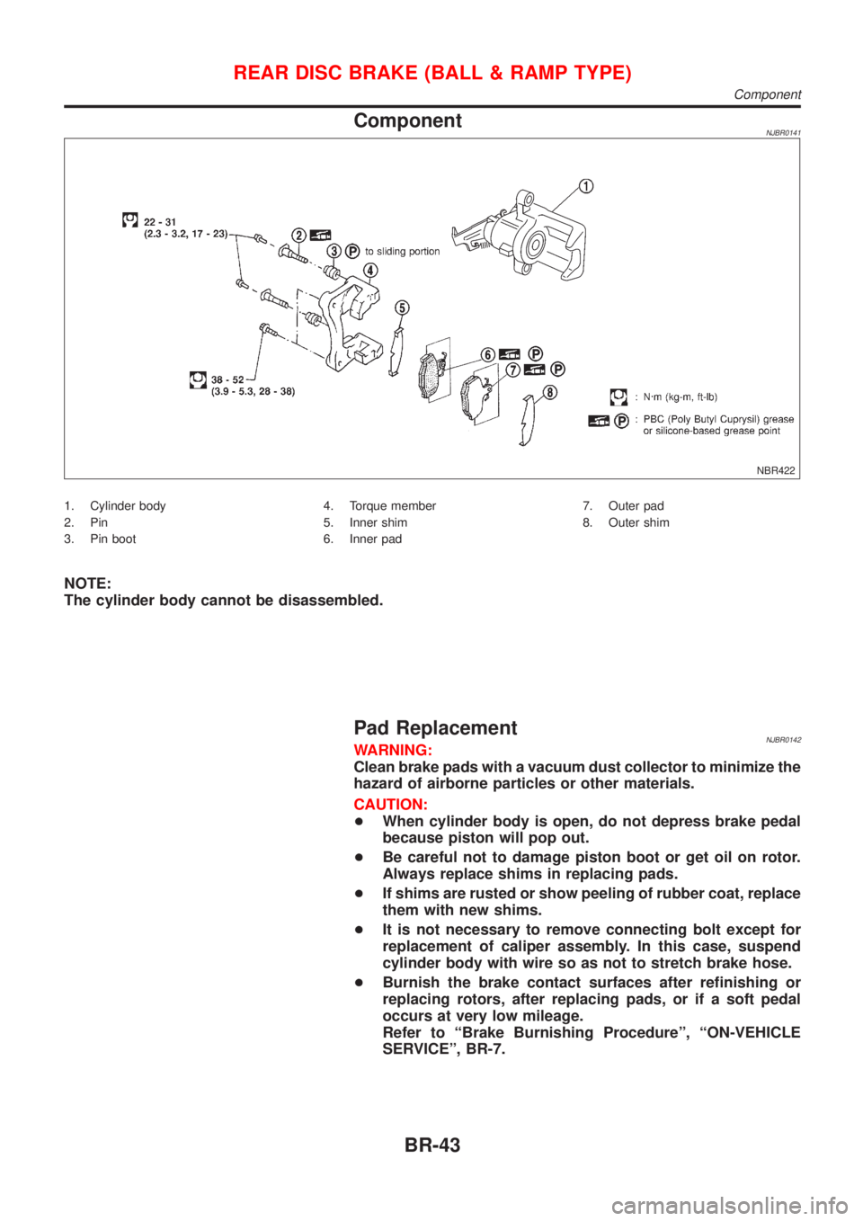
NBR422
1. Cylinder body
2. Pin
3. Pin boot4. Torque member
5. Inner shim
6. Inner pad7. Outer pad
8. Outer shim
NOTE:
The cylinder body cannot be disassembled.
Pad ReplacementNJBR0142WARNING:
Clean brake pads with a vacuum dust collector to minimize the
hazard of airborne particles or other materials.
CAUTION:
+When cylinder body is open, do not depress brake pedal
because piston will pop out.
+Be careful not to damage piston boot or get oil on rotor.
Always replace shims in replacing pads.
+If shims are rusted or show peeling of rubber coat, replace
them with new shims.
+It is not necessary to remove connecting bolt except for
replacement of caliper assembly. In this case, suspend
cylinder body with wire so as not to stretch brake hose.
+Burnish the brake contact surfaces after refinishing or
replacing rotors, after replacing pads, or if a soft pedal
occurs at very low mileage.
Refer to ªBrake Burnishing Procedureº, ªON-VEHICLE
SERVICEº, BR-7.
REAR DISC BRAKE (BALL & RAMP TYPE)
Component
BR-43
Page 1744 of 2493
SBR219C
ROTORNJBR0145S02Rubbing SurfaceNJBR0145S0201Check rotor for roughness, cracks or chips.
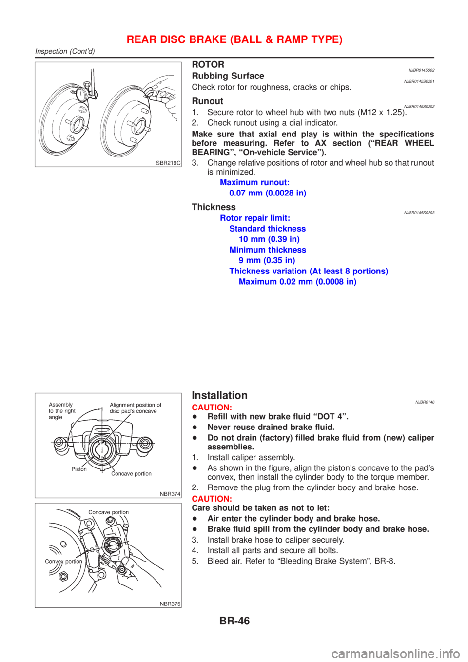
RunoutNJBR0145S02021. Secure rotor to wheel hub with two nuts (M12 x 1.25).
2. Check runout using a dial indicator.
Make sure that axial end play is within the specifications
before measuring. Refer to AX section (ªREAR WHEEL
BEARINGº, ªOn-vehicle Serviceº).
3. Change relative positions of rotor and wheel hub so that runout
is minimized.
Maximum runout:
0.07 mm (0.0028 in)
ThicknessNJBR0145S0203Rotor repair limit:
Standard thickness
10 mm (0.39 in)
Minimum thickness
9 mm (0.35 in)
Thickness variation (At least 8 portions)
Maximum 0.02 mm (0.0008 in)
NBR374
NBR375
InstallationNJBR0146CAUTION:
+Refill with new brake fluid ªDOT 4º.
+Never reuse drained brake fluid.
+Do not drain (factory) filled brake fluid from (new) caliper
assemblies.
1. Install caliper assembly.
+As shown in the figure, align the piston's concave to the pad's
convex, then install the cylinder body to the torque member.
2. Remove the plug from the cylinder body and brake hose.
CAUTION:
Care should be taken as not to let:
+Air enter the cylinder body and brake hose.
+Brake fluid spill from the cylinder body and brake hose.
3. Install brake hose to caliper securely.
4. Install all parts and secure all bolts.
5. Bleed air. Refer to ªBleeding Brake Systemº, BR-8.
REAR DISC BRAKE (BALL & RAMP TYPE)
Inspection (Cont'd)
BR-46
Page 1749 of 2493
This components controls the hydraulic circuit and increases, holds
or decreases hydraulic pressure to all or individual wheels. The
ABS actuator and electric unit can not be disassembled and can
be only serviced as an assembly.
ABS Actuator OperationNJBR0087S0301
Inlet solenoid
valveOutlet solenoid
valve
Normal brake operation OFF (Open) OFF (Closed)Master cylinder brake fluid pressure is directly
transmitted to caliper via the inlet solenoid valve.
ABS operationPressure hold ON (Closed) OFF (Closed)Hydraulic circuit is shut off to hold the caliper brake
fluid pressure.
Pressure
decreaseON (Closed) ON (Open)Caliper brake fluid is sent to reservoir via the outlet
solenoid valve. Then it is pushed up to the master
cylinder by pump.
Pressure
increaseOFF (Open) OFF (Closed)Master cylinder brake fluid pressure is transmitted
to caliper.
DESCRIPTIONABS
System Description (Cont'd)
BR-51
Page 1762 of 2493
SEF233G
SEF234G
How to Perform Trouble Diagnoses for Quick
and Accurate Repair
NJBR0094INTRODUCTIONNJBR0094S01The ABS system has an electronic control unit to control major
functions. The control unit accepts input signals from sensors and
instantly drives actuator. It is essential that both kinds of signals are
proper and stable. It is also important to check for conventional
problems: such as air leaks in the booster or lines, lack of brake
fluid, or other problems with the brake system.
It is much more difficult to diagnose a problem that occurs intermit-
tently rather than continuously. Most intermittent problems are
caused by poor electric connections or faulty wiring. In this case,
careful checking of suspicious circuits may help prevent the
replacement of good parts.
A visual check only may not find the cause of the problems, so a
road test should be performed.
Before undertaking actual checks, take just a few minutes to talk
with a customer who approaches with a ABS complaint. The cus-
tomer is a very good source of information on such problems;
especially intermittent ones. Through the talks with the customer,
find out what symptoms are present and under what conditions
they occur.
Start your diagnosis by looking for ªconventionalº problems first.
This is one of the best ways to troubleshoot brake problems on an
ABS controlled vehicle. Also check related Service Bulletins for
information.
TROUBLE DIAGNOSIS Ð INTRODUCTIONABS
How to Perform Trouble Diagnoses for Quick and Accurate Repair
BR-64
Page 1778 of 2493
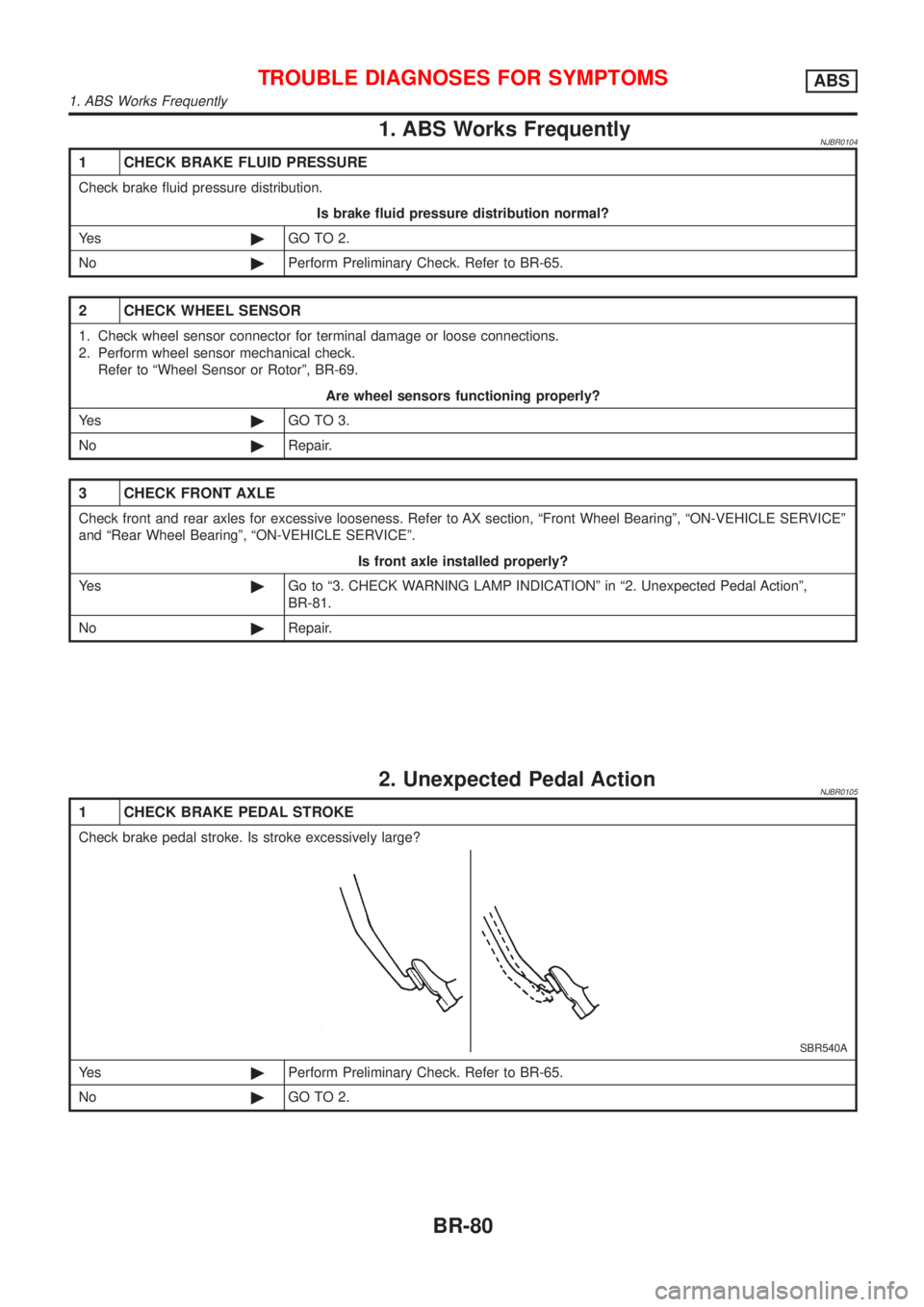
1. ABS Works FrequentlyNJBR0104
1 CHECK BRAKE FLUID PRESSURE
Check brake fluid pressure distribution.
Is brake fluid pressure distribution normal?
Ye s©GO TO 2.
No©Perform Preliminary Check. Refer to BR-65.
2 CHECK WHEEL SENSOR
1. Check wheel sensor connector for terminal damage or loose connections.
2. Perform wheel sensor mechanical check.
Refer to ªWheel Sensor or Rotorº, BR-69.
Are wheel sensors functioning properly?
Ye s©GO TO 3.
No©Repair.
3 CHECK FRONT AXLE
Check front and rear axles for excessive looseness. Refer to AX section, ªFront Wheel Bearingº, ªON-VEHICLE SERVICEº
and ªRear Wheel Bearingº, ªON-VEHICLE SERVICEº.
Is front axle installed properly?
Ye s©Go to ª3. CHECK WARNING LAMP INDICATIONº in ª2. Unexpected Pedal Actionº,
BR-81.
No©Repair.
2. Unexpected Pedal ActionNJBR0105
1 CHECK BRAKE PEDAL STROKE
Check brake pedal stroke. Is stroke excessively large?
SBR540A
Ye s©Perform Preliminary Check. Refer to BR-65.
No©GO TO 2.
TROUBLE DIAGNOSES FOR SYMPTOMSABS
1. ABS Works Frequently
BR-80
Page 1789 of 2493
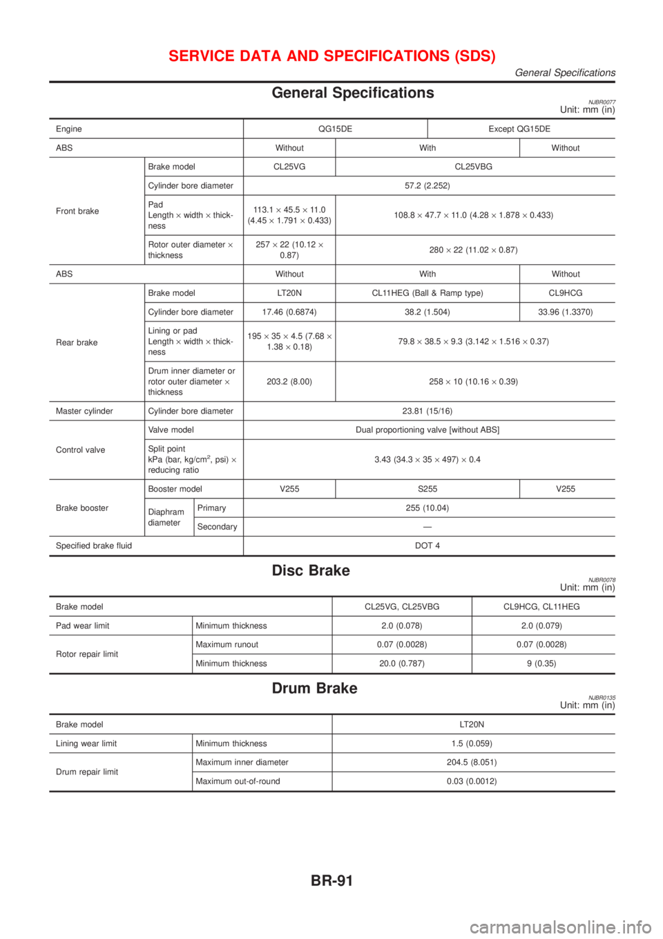
General SpecificationsNJBR0077Unit: mm (in)
Engine QG15DE Except QG15DE
ABS Without With Without
Front brakeBrake model CL25VG CL25VBG
Cylinder bore diameter 57.2 (2.252)
Pad
Length´width´thick-
ness113.1´45.5´11.0
(4.45´1.791´0.433)108.8´47.7´11.0 (4.28´1.878´0.433)
Rotor outer diameter´
thickness257´22 (10.12´
0.87)280´22 (11.02´0.87)
ABS Without With Without
Rear brakeBrake model LT20N CL11HEG (Ball & Ramp type) CL9HCG
Cylinder bore diameter 17.46 (0.6874) 38.2 (1.504) 33.96 (1.3370)
Lining or pad
Length´width´thick-
ness195´35´4.5 (7.68´
1.38´0.18)79.8´38.5´9.3 (3.142´1.516´0.37)
Drum inner diameter or
rotor outer diameter´
thickness203.2 (8.00) 258´10 (10.16´0.39)
Master cylinder Cylinder bore diameter 23.81 (15/16)
Control valveValve model Dual proportioning valve [without ABS]
Split point
kPa (bar, kg/cm
2, psi)´
reducing ratio3.43 (34.3´35´497)´0.4
Brake boosterBooster model V255 S255 V255
Diaphram
diameterPrimary 255 (10.04)
Secondary Ð
Specified brake fluidDOT 4
Disc BrakeNJBR0078Unit: mm (in)
Brake model CL25VG, CL25VBG CL9HCG, CL11HEG
Pad wear limit Minimum thickness 2.0 (0.078) 2.0 (0.079)
Rotor repair limitMaximum runout 0.07 (0.0028) 0.07 (0.0028)
Minimum thickness 20.0 (0.787) 9 (0.35)
Drum BrakeNJBR0135Unit: mm (in)
Brake modelLT20N
Lining wear limit Minimum thickness 1.5 (0.059)
Drum repair limitMaximum inner diameter 204.5 (8.051)
Maximum out-of-round 0.03 (0.0012)
SERVICE DATA AND SPECIFICATIONS (SDS)
General Specifications
BR-91