Page 128 of 2493

WARNING:
+Position vehicle on a flat and solid surface.
+Place chocks at front and back of rear wheels.
+Do not remove engine until exhaust system has com-
pletely cooled off, otherwise, you may burn yourself
and/or fire may break out in fuel line.
+Before disconnecting fuel hose, release pressure.
Refer to EC-38, ªFuel Pressure Releaseº.
+Be sure to lift engine and transaxle in a safe manner.
+For engines not equipped with engine slingers, attach
proper slingers and bolts described in PARTS CATALOG.
CAUTION:
+When lifting engine, be sure to clear surrounding parts.
Use special care near accelerator wire casing, brake lines
and brake master cylinder.
+When lifting the engine, always use engine slingers in a
safe manner.
+When removing drive shaft, be careful not to damage
grease seal of transaxle.
+Before separating engine and transaxle, remove crank-
shaft position sensor (POS) from the cylinder block
assembly.
+Always be extra careful not to damage edge of crankshaft
position sensor (POS), or signal plate teeth.
Engine cannot be removed separately from transaxle. Remove
engine with transaxle as an assembly.
REMOVALNJEM0022S011. Drain coolant from radiator and cylinder block. Refer to LC-17,
ªChanging Engine Coolantº.
2. Remove coolant reservoir tank and bracket.
3. Drain engine oil.
4. Remove battery and battery tray.
5. Remove air cleaner and air duct.
6. Remove drive belts.
7. Remove alternator and air conditioner compressor from
engine.
8. Remove power steering oil pump from engine and position
aside.
Power steering oil pump does not need to be disconnected
from power steering tubes.
ENGINE ASSEMBLYQG
Removal and Installation (Cont'd)
EM-50
Page 130 of 2493
ComponentsNJEM0023
YEM022
1. Oil level gauge guide
2. Cylinder block
3. Rear oil seal retainer
4. Rear oil seal
5. Rear plate
6. Flywheel
7. Drain plug
8. Buffle plate
9. Top ring10. 2nd ring
11. Oil ring
12. Piston
13. Snap ring
14. Piston pin
15. Connecting rod
16. Connecting rod bearing
17. Connecting rod cap
18. Key19. Main bearing
20. Thrust bearing
21. Crankshaft
22. Main bearing cap
23. Knock sensor
24. Crankshaft position sensor (POS)
25. Rear lower plate
26. Drive plate
27. Signal plate
CYLINDER BLOCKQG
Components
EM-52
Page 131 of 2493

Removal and InstallationNJEM0024CAUTION:
+When installing sliding parts such as bearings and
pistons, apply engine oil on the sliding surfaces.
+Place removed parts, such as bearings and bearing caps,
in their proper order and direction.
+When installing connecting rod nuts and main bearing cap
bolts, apply new engine oil to threads and seating sur-
faces.
+Do not allow any magnetic materials to contact the signal
plate teeth of flywheel or drive plate, and rear plate.
+Remove the crankshaft position sensor (POS).
+Be careful not to damage sensor edges and single plate
teeth.
SEM927F
DisassemblyNJEM0025PISTON AND CRANKSHAFTNJEM0025S011. Place engine on a work stand.
2. Drain coolant and oil.
3. Remove timing chain.
Refer to EM-23.
SEM877B
4. Remove pistons with connecting rod.
+When disassembling piston and connecting rod, remove snap
ring first. Then heat piston to 60 to 70ÉC (140 to 158ÉF) or use
piston pin press stand at room temperature.
CAUTION:
+When piston rings are not replaced, make sure that piston
rings are mounted in their original positions.
+When replacing piston rings, if there is no punch mark,
install with either side up.
SEM165DB
5. Loosen main bearing caps in numerical order as shown in fig-
ure.
6. Remove bearing caps, main bearings and crankshaft.
+Before removing bearing caps, measure crankshaft end
play. Refer to EM-61.
+Bolts should be loosened in two or three steps.
CYLINDER BLOCKQG
Removal and Installation
EM-53
Page 138 of 2493

SEM062A
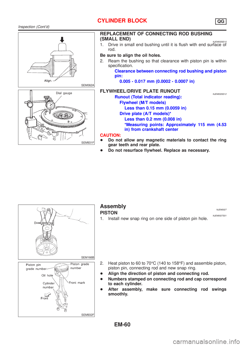
REPLACEMENT OF CONNECTING ROD BUSHING
(SMALL END)
NJEM0026S101. Drive in small end bushing until it is flush with end surface of
rod.
Be sure to align the oil holes.
2. Ream the bushing so that clearance with piston pin is within
specification.
Clearance between connecting rod bushing and piston
pin:
0.005 - 0.017 mm (0.0002 - 0.0007 in)
SEM931F
FLYWHEEL/DRIVE PLATE RUNOUTNJEM0026S12Runout (Total indicator reading):
Flywheel (M/T models)
Less than 0.15 mm (0.0059 in)
Drive plate (A/T models)*
Less than 0.2 mm (0.008 in)
*Measuring points: Approximately 115 mm (4.53
in) from crankshaft center
CAUTION:
+Do not allow any magnetic materials to contact the ring
gear teeth and rear plate.
+Do not resurface flywheel. Replace as necessary.
SEM166B
AssemblyNJEM0027PISTONNJEM0027S011. Install new snap ring on one side of piston pin hole.
SEM932F
2. Heat piston to 60 to 70ÉC (140 to 158ÉF) and assemble piston,
piston pin, connecting rod and new snap ring.
+Align the direction of piston and connecting rod.
+Numbers stamped on connecting rod and cap correspond
to each cylinder.
+After assembly, make sure connecting rod swings
smoothly.
CYLINDER BLOCKQG
Inspection (Cont'd)
EM-60
Page 153 of 2493
Connecting Rod BearingNJEM0038STANDARD SIZENJEM0038S01Unit: mm (in)
Grade No. Thickness Identification color or number
0 1.503 - 1.506 (0.0592 - 0.0593) Ð
1 1.506 - 1.509 (0.0593 - 0.0594) Brown
2 1.509 - 1.512 (0.0594 - 0.0595) Green
UNDERSIZENJEM0038S02Unit: mm (in)
Grade No. Thickness Identification color or number
0.08 (0.0031) 1.542 - 1.546 (0.0607 - 0.0609) Ð
0.12 (0.0047) 1.562 - 1.566 (0.0615 - 0.0617) Ð
0.25 (0.0098) 1.627 - 1.631 (0.0641 - 0.0642) Ð
Bearing ClearanceNJEM0039Unit: mm (in)
Main bearing clearanceStandard 0.020 - 0.044 (0.0008 - 0.0017)
Limit 0.1 (0.004)
Connecting rod bearing clearanceStandard 0.014 - 0.039 (0.0006 - 0.0015)
Limit 0.1 (0.004)
Miscellaneous ComponentsNJEM0040Unit: mm (in)
Flywheel runout [TIR*]Less than 0.15 (0.0059)
Drive plate runout [TIR*]Less than 0.2 (0.008)
Camshaft sprocket runout [TIR*] Less than 0.15 (0.0059)
*: Total indicator reading
SERVICE DATA AND SPECIFICATIONS (SDS)QG
Connecting Rod Bearing
EM-75
Page 191 of 2493
CAUTION:
Do not disassemble or adjust the turbocharger body.
AssemblyNJEM0103S0102When a stud bolt is pulled out, tighten it to the following torque:
: 24 - 27 N´m (2.4 - 2.8 kg-m, 18 - 20 ft-lb)
JEM267G
InspectionNJEM0104EXHAUST MANIFOLDNJEM0104S01Check the distortion on the mounting surface in the six directions
using a straightedge and a feeler gauge.
Limit: 0.3 mm (0.012 in)
TURBOCHARGERNJEM0104S02
SEM269G
CAUTION:
When the compressor wheel, turbine wheel, or rotor shaft is
damaged, remove all the fragments and foreign matter left in
the following passages in order to prevent a secondary failure:
Suction side: Between turbocharger and air cleaner
Exhaust side: Between turbocharger and catalytic con-
verter
EXHAUST MANIFOLD, TURBOCHARGERYD
Disassembly and Assembly (Cont'd)
EM-113
Page 192 of 2493

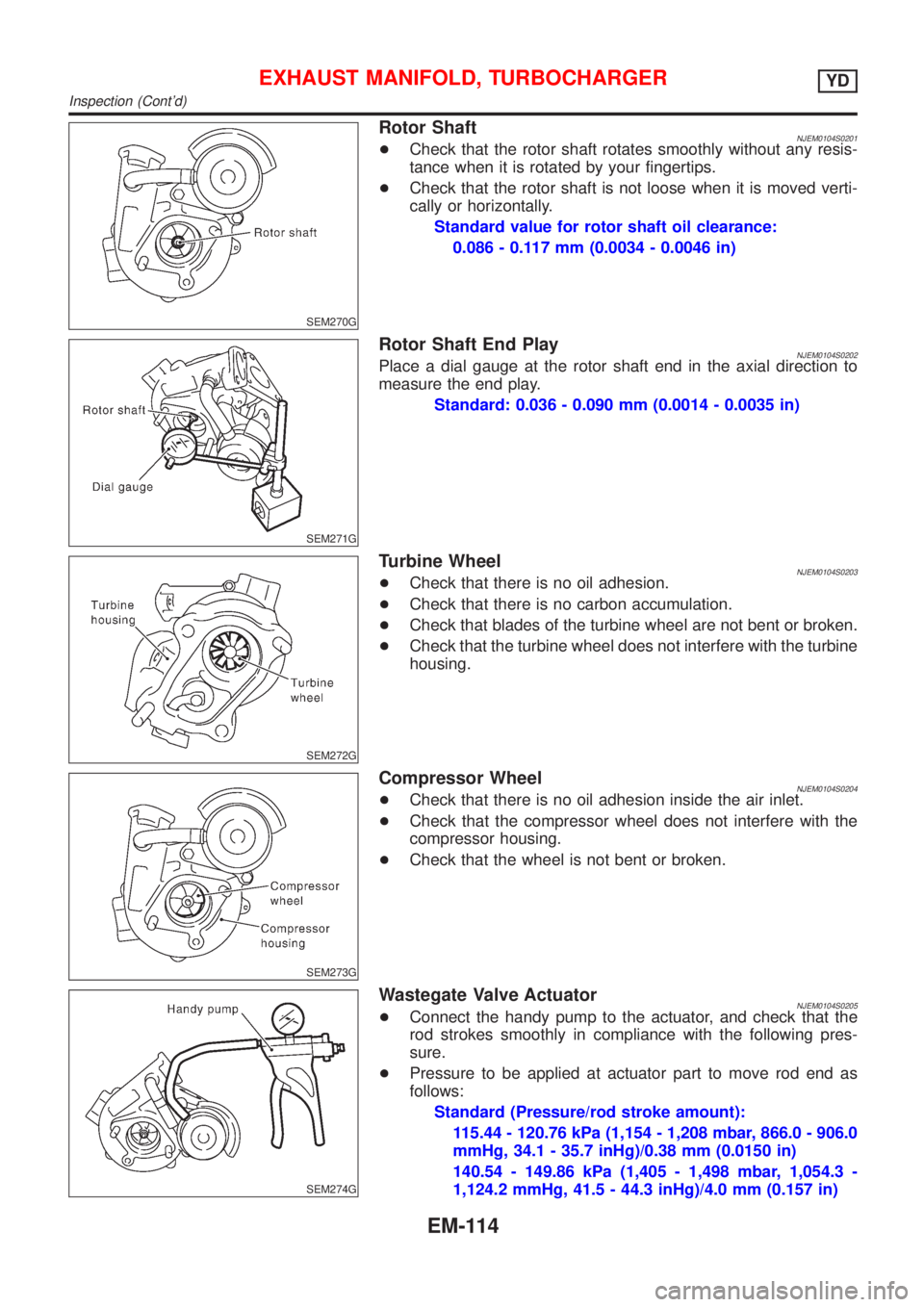
SEM270G
Rotor ShaftNJEM0104S0201+Check that the rotor shaft rotates smoothly without any resis-
tance when it is rotated by your fingertips.
+Check that the rotor shaft is not loose when it is moved verti-
cally or horizontally.
Standard value for rotor shaft oil clearance:
0.086 - 0.117 mm (0.0034 - 0.0046 in)
SEM271G
Rotor Shaft End PlayNJEM0104S0202Place a dial gauge at the rotor shaft end in the axial direction to
measure the end play.
Standard: 0.036 - 0.090 mm (0.0014 - 0.0035 in)
SEM272G
Turbine WheelNJEM0104S0203+Check that there is no oil adhesion.
+Check that there is no carbon accumulation.
+Check that blades of the turbine wheel are not bent or broken.
+Check that the turbine wheel does not interfere with the turbine
housing.
SEM273G
Compressor WheelNJEM0104S0204+Check that there is no oil adhesion inside the air inlet.
+Check that the compressor wheel does not interfere with the
compressor housing.
+Check that the wheel is not bent or broken.
SEM274G
Wastegate Valve ActuatorNJEM0104S0205+Connect the handy pump to the actuator, and check that the
rod strokes smoothly in compliance with the following pres-
sure.
+Pressure to be applied at actuator part to move rod end as
follows:
Standard (Pressure/rod stroke amount):
115.44 - 120.76 kPa (1,154 - 1,208 mbar, 866.0 - 906.0
mmHg, 34.1 - 35.7 inHg)/0.38 mm (0.0150 in)
140.54 - 149.86 kPa (1,405 - 1,498 mbar, 1,054.3 -
1,124.2 mmHg, 41.5 - 44.3 inHg)/4.0 mm (0.157 in)
EXHAUST MANIFOLD, TURBOCHARGERYD
Inspection (Cont'd)
EM-114
Page 193 of 2493

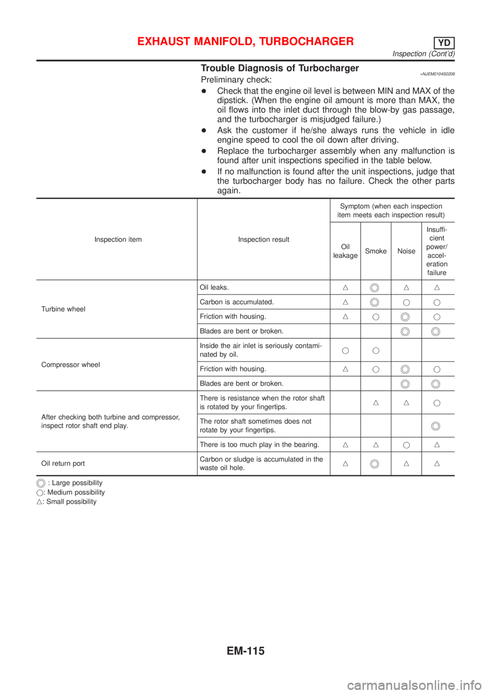
Trouble Diagnosis of Turbocharger=NJEM0104S0206Preliminary check:
+Check that the engine oil level is between MIN and MAX of the
dipstick. (When the engine oil amount is more than MAX, the
oil flows into the inlet duct through the blow-by gas passage,
and the turbocharger is misjudged failure.)
+Ask the customer if he/she always runs the vehicle in idle
engine speed to cool the oil down after driving.
+Replace the turbocharger assembly when any malfunction is
found after unit inspections specified in the table below.
+If no malfunction is found after the unit inspections, judge that
the turbocharger body has no failure. Check the other parts
again.
Inspection item Inspection resultSymptom (when each inspection
item meets each inspection result)
Oil
leakageSmoke NoiseInsuffi-
cient
power/
accel-
eration
failure
Turbine wheelOil leaks.n
nn
Carbon is accumulated.n
jj
Friction with housing.nj
j
Blades are bent or broken.
Compressor wheelInside the air inlet is seriously contami-
nated by oil.jj
Friction with housing.njj
Blades are bent or broken.
After checking both turbine and compressor,
inspect rotor shaft end play.There is resistance when the rotor shaft
is rotated by your fingertips.nnj
The rotor shaft sometimes does not
rotate by your fingertips.
There is too much play in the bearing.nnjn
Oil return portCarbon or sludge is accumulated in the
waste oil hole.n
nn
: Large possibility
j: Medium possibility
n: Small possibility
EXHAUST MANIFOLD, TURBOCHARGERYD
Inspection (Cont'd)
EM-115