Page 147 of 2493
2.60 (0.1024) 260
2.61 (0.1028) 261
2.62 (0.1031) 262
2.63 (0.1035) 263
2.64 (0.1039) 264
2.65 (0.1043) 265
2.66 (0.1047) 266
2.68 (0.1055) 268
2.70 (0.1063) 270
2.72 (0.1071) 272
2.74 (0.1079) 274
2.76 (0.1087) 276
2.78 (0.1094) 278
2.80 (0.1102) 280
2.82 (0.1110) 282
2.84 (0.1118) 284
2.86 (0.1126) 286
2.88 (0.1134) 288
2.90 (0.1142) 290
2.92 (0.1150) 292
2.94 (0.1157) 294
2.96 (0.1165) 296
2.98 (0.1173) 298
SERVICE DATA AND SPECIFICATIONS (SDS)QG
Valve (Cont'd)
EM-69
Page 148 of 2493
AEM236
VALVE SEATNJEM0031S05Unit: mm (in)
SEM573DASEM685G
Dia. QG15DE QG18DE
A 26.8 - 27.0 (1.055 - 1.063) 27.8 - 28.0 (1.094 - 1.102)
B 28.5 - 28.7 (1.122 - 1.130) 29.5 - 29.7 (1.161 - 1.169)
C 30.2 - 30.4 (1.189 - 1.197) 31.9 - 32.1 (1.256 - 1.264)
D 30.500 - 30.516 (1.2008 - 1.2014) 31.500 - 31.516 (1.2402 - 1.2408)
E 23.5 - 23.7 (0.925 - 0.933) 24.5 - 24.7 (0.9646 - 0.9724)
F 25.2 - 25.4 (0.992 - 1.000) 26.2 - 26.4 (1.031 - 1.039)
G 25.500 - 25.516 (1.0039 - 1.0046) 26.500 - 26.516 (1.043 - 1.0439)
SERVICE DATA AND SPECIFICATIONS (SDS)QG
Valve (Cont'd)
EM-70
Page 149 of 2493
VALVE SEAT RESURFACE LIMITNJEM0031S08Unit: mm (in)
AEM343
Depth (L)Intake 35.95 - 36.55 (1.4154 - 1.4390)
Exhaust 35.92 - 36.52 (1.4142 - 1.4378)
Camshaft and Camshaft BearingNJEM0032Unit: mm (in)
Engine modelQG
Cam height ªAºIntake 40.610 - 40.800 (1.5988 - 1.6063)
Exhaust 40.056 - 40.246 (1.5770 - 1.5845)
Cam wear limit0.20 (0.0079)
EM671
Standard Limit
Camshaft journal to bearing clearance 0.045 - 0.086 (0.0018 - 0.0034) 0.15 (0.0059)
Inner diameter of camshaft bearingNo. 1 28.000 - 28.021 (1.1024 - 1.1032)
Ð
No. 2 to No. 5 24.000 - 24.021 (0.9449 - 0.9457)
Outer diameter of camshaft journalNo. 1 27.935 - 27.955 (1.0998 - 1.1006)
Ð
No. 2 to No. 5 23.935 - 23.955 (0.9423 - 0.9431)
Camshaft runout [TIR*] Less than 0.02 (0.0008) 0.1 (0.004)
Camshaft end play 0.115 - 0.188 (0.0045 - 0.0074) 0.20 (0.0079)
*Total indicator reading
SERVICE DATA AND SPECIFICATIONS (SDS)QG
Valve (Cont'd)
EM-71
Page 155 of 2493
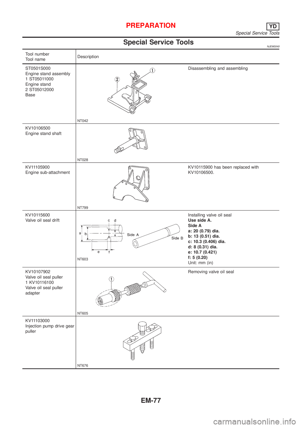
Special Service ToolsNJEM0049
Tool number
Tool nameDescription
ST0501S000
Engine stand assembly
1 ST05011000
Engine stand
2 ST05012000
Base
NT042
Disassembling and assembling
KV10106500
Engine stand shaft
NT028
KV11105900
Engine sub-attachment
NT799
KV10115900 has been replaced with
KV10106500.
KV10115600
Valve oil seal drift
NT603
Installing valve oil seal
Use side A.
Side A
a: 20 (0.79) dia.
b: 13 (0.51) dia.
c: 10.3 (0.406) dia.
d: 8 (0.31) dia.
e: 10.7 (0.421)
f: 5 (0.20)
Unit: mm (in)
KV10107902
Valve oil seal puller
1 KV10116100
Valve oil seal puller
adapter
NT605
Removing valve oil seal
KV11103000
Injection pump drive gear
puller
NT676
PREPARATIONYD
Special Service Tools
EM-77
Page 157 of 2493
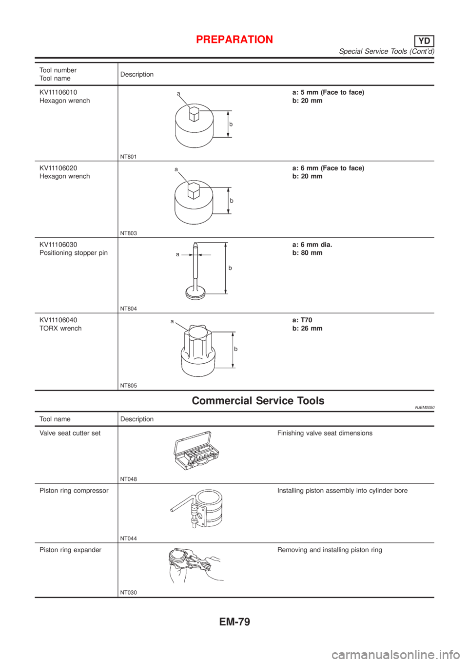
Tool number
Tool nameDescription
KV11106010
Hexagon wrench
NT801
a: 5 mm (Face to face)
b: 20 mm
KV11106020
Hexagon wrench
NT803
a: 6 mm (Face to face)
b: 20 mm
KV11106030
Positioning stopper pin
NT804
a: 6 mm dia.
b: 80 mm
KV11106040
TORX wrench
NT805
a: T70
b: 26 mm
Commercial Service ToolsNJEM0050
Tool name Description
Valve seat cutter set
NT048
Finishing valve seat dimensions
Piston ring compressor
NT044
Installing piston assembly into cylinder bore
Piston ring expander
NT030
Removing and installing piston ring
PREPARATIONYD
Special Service Tools (Cont'd)
EM-79
Page 202 of 2493
SEM008A
VALVE GUIDE REPLACEMENTNJEM0065S09+When a valve guide is removed, replace with an oversized [0.2
mm (0.008 in)] valve guide.
1. To remove valve guide, heat cylinder head to 110 to 130ÉC
(230 to 266ÉF) by soaking in heated oil.
SEM931C
2. Drive out valve guide with a press [under a 20 kN (2 ton, 2.2
US ton, 2.0 Imp ton) pressure] or hammer and suitable tool.
SEM932C
3. Ream cylinder head valve guide hole.
Valve guide hole diameter (for service parts):
10.175 - 10.196 mm (0.4006 - 0.4014 in)
JEM156G
4. Heat cylinder head to 110 to 130ÉC (230 to 266ÉF) and press
service valve guide onto cylinder head.
Projection ªLº:
10.4 - 10.6 mm (0.409 - 0.417 in)
5. Ream valve guide.
Finished size:
6.000 - 6.018 mm (0.2362 - 0.2369 in)
CYLINDER HEADYD
Inspection (Cont'd)
EM-124
Page 203 of 2493
SEM934C
JEM157G
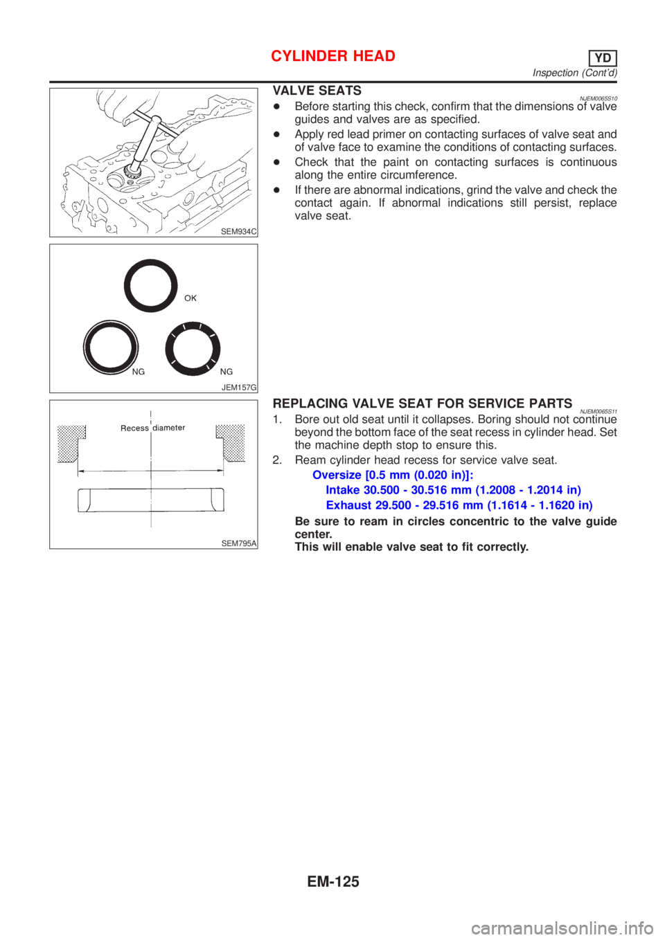
VALVE SEATSNJEM0065S10+Before starting this check, confirm that the dimensions of valve
guides and valves are as specified.
+Apply red lead primer on contacting surfaces of valve seat and
of valve face to examine the conditions of contacting surfaces.
+Check that the paint on contacting surfaces is continuous
along the entire circumference.
+If there are abnormal indications, grind the valve and check the
contact again. If abnormal indications still persist, replace
valve seat.
SEM795A
REPLACING VALVE SEAT FOR SERVICE PARTSNJEM0065S111. Bore out old seat until it collapses. Boring should not continue
beyond the bottom face of the seat recess in cylinder head. Set
the machine depth stop to ensure this.
2. Ream cylinder head recess for service valve seat.
Oversize [0.5 mm (0.020 in)]:
Intake 30.500 - 30.516 mm (1.2008 - 1.2014 in)
Exhaust 29.500 - 29.516 mm (1.1614 - 1.1620 in)
Be sure to ream in circles concentric to the valve guide
center.
This will enable valve seat to fit correctly.
CYLINDER HEADYD
Inspection (Cont'd)
EM-125
Page 221 of 2493
JEM200G
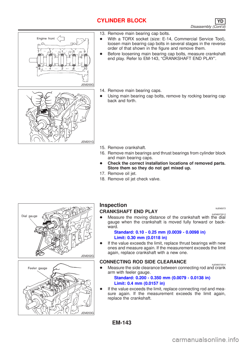
13. Remove main bearing cap bolts.
+With a TORX socket (size: E-14, Commercial Service Tool),
loosen main bearing cap bolts in several stages in the reverse
order of that shown in the figure and remove them.
+Before loosening main bearing cap bolts, measure crankshaft
end play. Refer to EM-143, ªCRANKSHAFT END PLAYº.
JEM201G
14. Remove main bearing caps.
+Using main bearing cap bolts, remove by rocking bearing cap
back and forth.
15. Remove crankshaft.
16. Remove main bearings and thrust bearings from cylinder block
and main bearing caps.
+Check the correct installation locations of removed parts.
Store them so they do not get mixed up.
17. Remove oil jet.
18. Remove oil jet check valve.
JEM202G
InspectionNJEM0073CRANKSHAFT END PLAYNJEM0073S13+Measure the moving distance of the crankshaft with the dial
gauge when the crankshaft is moved fully forward or back-
ward.
Standard: 0.10 - 0.25 mm (0.0039 - 0.0098 in)
Limit: 0.30 mm (0.0118 in)
+If the value exceeds the limit, replace thrust bearings with new
ones and measure again. If the measurement exceeds the limit
again, replace crankshaft with a new one.
JEM203G
CONNECTING ROD SIDE CLEARANCENJEM0073S14+Measure the side clearance between connecting rod and crank
arm with feeler gauge.
Standard: 0.200 - 0.350 mm (0.0079 - 0.0138 in)
Limit: 0.4 mm (0.0157 in)
+If the value exceeds the limit, replace connecting rod and mea-
sure again. If the measurement exceeds the limit again,
replace the crankshaft.
CYLINDER BLOCKYD
Disassembly (Cont'd)
EM-143


![NISSAN ALMERA N16 2001 Electronic Repair Manual SEM008A
VALVE GUIDE REPLACEMENTNJEM0065S09+When a valve guide is removed, replace with an oversized [0.2
mm (0.008 in)] valve guide.
1. To remove valve guide, heat cylinder head to 110 to 130ÉC
(230](/manual-img/5/57351/w960_57351-201.png "NISSAN ALMERA N16 2001 Electronic Repair Manual SEM008A
VALVE GUIDE REPLACEMENTNJEM0065S09+When a valve guide is removed, replace with an oversized [0.2
mm (0.008 in)] valve guide.
1. To remove valve guide, heat cylinder head to 110 to 130ÉC
(230")