Page 85 of 2493
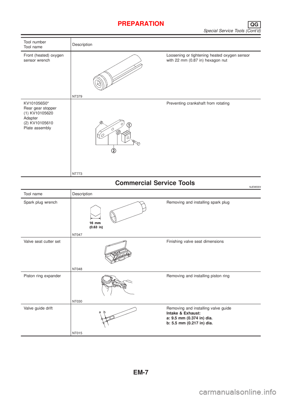
Tool number
Tool nameDescription
Front (heated) oxygen
sensor wrench
NT379
Loosening or tightening heated oxygen sensor
with 22 mm (0.87 in) hexagon nut
KV101056S0*
Rear gear stopper
(1) KV10105620
Adapter
(2) KV10105610
Plate assembly
NT773
Preventing crankshaft from rotating
Commercial Service ToolsNJEM0004
Tool name Description
Spark plug wrench
NT047
Removing and installing spark plug
Valve seat cutter set
NT048
Finishing valve seat dimensions
Piston ring expander
NT030
Removing and installing piston ring
Valve guide drift
NT015
Removing and installing valve guide
Intake & Exhaust:
a: 9.5 mm (0.374 in) dia.
b: 5.5 mm (0.217 in) dia.
PREPARATIONQG
Special Service Tools (Cont'd)
EM-7
Page 86 of 2493
Tool name Description
Valve guide reamer
NT016
Reaming valve guide1or hole for oversize valve
guide2
Intake & Exhaust:
d
1: 5.5 mm (0.217 in) dia.
d
2: 9.685 mm (0.3813 in) dia.
Front oil seal drift
NT049
Installing front oil seal
a: 52 mm (2.05 in) dia.
b: 40 mm (1.57 in) dia.
Rear oil seal drift
NT049
Installing rear oil seal
a: 103 mm (4.06 in) dia.
b: 84 mm (3.31 in) dia.
Oxygen sensor thread
cleaner
NT778
Reconditioning the exhaust system threads before
installing a new oxygen sensor. Use with anti-
seize lubricant shown below.
a: 18 mm dia. with a pitch of 1.5 mm for Zirco-
nia Oxygen Sensor
b: 12 mm dia. with a pitch of 1.25 mm for Tita-
nia Oxygen Sensor
Anti-seize lubricant (Per-
matex
TM133AR or
equivalent meeting MIL
specification MIL-A-907)
NT779
Lubricating oxygen sensor thread cleaning tool
when reconditioning exhaust system threads
PREPARATIONQG
Commercial Service Tools (Cont'd)
EM-8
Page 117 of 2493
Unit: mm (in)
Standard Limit
Intake0.020 - 0.050
(0.0008 - 0.0020)0.1 (0.004)
Exhaust0.040 - 0.070
(0.0016 - 0.0028)0.1 (0.004)
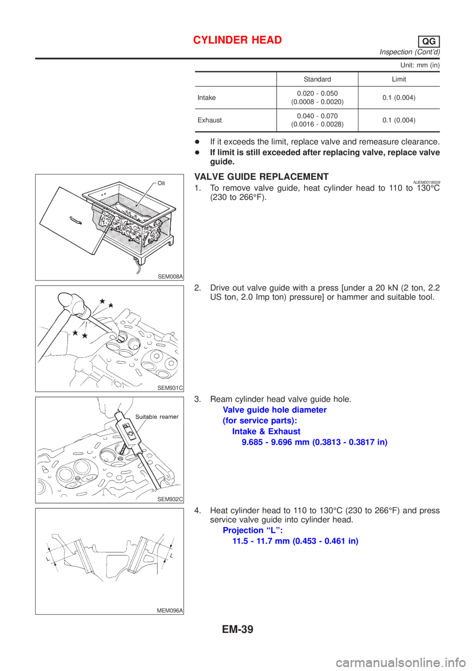
+If it exceeds the limit, replace valve and remeasure clearance.
+If limit is still exceeded after replacing valve, replace valve
guide.
SEM008A
VALVE GUIDE REPLACEMENTNJEM0019S091. To remove valve guide, heat cylinder head to 110 to 130ÉC
(230 to 266ÉF).
SEM931C
2. Drive out valve guide with a press [under a 20 kN (2 ton, 2.2
US ton, 2.0 Imp ton) pressure] or hammer and suitable tool.
SEM932C
3. Ream cylinder head valve guide hole.
Valve guide hole diameter
(for service parts):
Intake & Exhaust
9.685 - 9.696 mm (0.3813 - 0.3817 in)
MEM096A
4. Heat cylinder head to 110 to 130ÉC (230 to 266ÉF) and press
service valve guide into cylinder head.
Projection ªLº:
11.5 - 11.7 mm (0.453 - 0.461 in)
CYLINDER HEADQG
Inspection (Cont'd)
EM-39
Page 118 of 2493
SEM932C
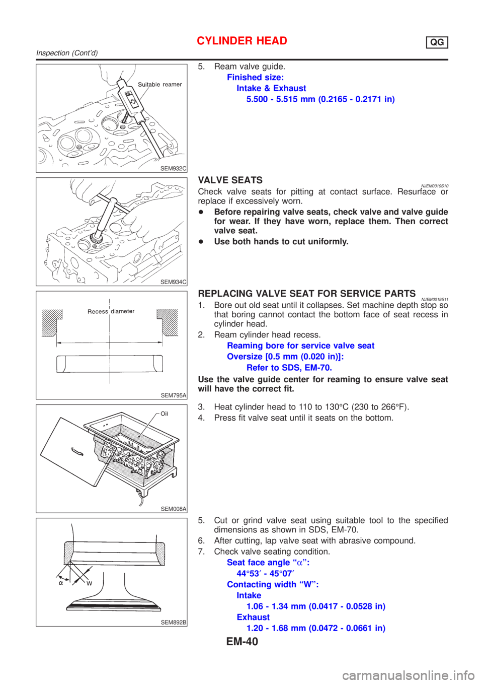
5. Ream valve guide.
Finished size:
Intake & Exhaust
5.500 - 5.515 mm (0.2165 - 0.2171 in)
SEM934C
VALVE SEATSNJEM0019S10Check valve seats for pitting at contact surface. Resurface or
replace if excessively worn.
+Before repairing valve seats, check valve and valve guide
for wear. If they have worn, replace them. Then correct
valve seat.
+Use both hands to cut uniformly.
SEM795A
REPLACING VALVE SEAT FOR SERVICE PARTSNJEM0019S111. Bore out old seat until it collapses. Set machine depth stop so
that boring cannot contact the bottom face of seat recess in
cylinder head.
2. Ream cylinder head recess.
Reaming bore for service valve seat
Oversize [0.5 mm (0.020 in)]:
Refer to SDS, EM-70.
Use the valve guide center for reaming to ensure valve seat
will have the correct fit.
SEM008A
3. Heat cylinder head to 110 to 130ÉC (230 to 266ÉF).
4. Press fit valve seat until it seats on the bottom.
SEM892B
5. Cut or grind valve seat using suitable tool to the specified
dimensions as shown in SDS, EM-70.
6. After cutting, lap valve seat with abrasive compound.
7. Check valve seating condition.
Seat face angle ªaº:
44É53¢- 45É07¢
Contacting width ªWº:
Intake
1.06 - 1.34 mm (0.0417 - 0.0528 in)
Exhaust
1.20 - 1.68 mm (0.0472 - 0.0661 in)
CYLINDER HEADQG
Inspection (Cont'd)
EM-40
Page 142 of 2493

General SpecificationsNJEM0028
EngineQG15DE QG18DE
ClassificationGasoline
Cylinder arrangement4, in-line
Displacement
cm
3(cu in)1,497 (91.35) 1,769 (107.94)
Bore´stroke
mm (in)73.6´88.0 (2.898´3.465) 80.0´88.0 (3.150´3.465)
Valve arrangementDOHC
Firing order1-3-4-2
Number of piston ringsCompression 2
Oil 1
Number of main bearings5
Compression ratio9.5 (9.9*)
*: For QG15DE for Europe
EM120
abcde f
Valve timingQG18DE 222É 236É 0É (20É) 56É (36É) þ2É 44É
QG15DE 222É 222É 0É 42É þ2É 44É
( ): Valve timing control ON
Compression PressureNJEM0029Unit: kPa (bar, kg/cm2, psi)/350 rpm
Standard1,324 (13.24, 13.5, 192)
1,372 (13.720, 13.99, 198.9)*
Minimum1,128 (11.28, 11.5, 164)
1,176 (11.759, 11.99, 170.5)*
Difference limit between cylinders 98 (0.98, 1.0, 14)
*: For QG15DE
Belt DeflectionNJEM0045Unit: mm (in)
Applied engineUsed belt deflection
Deflection of new belt
LimitDeflection after adjust-
ment
AlternatorWith air conditioner
compressorQG15´18DE 8.1 (0.319)5.3 - 5.7
(0.209 - 0.224)4.5 - 5.0
(0.177 - 0.197)
Without air conditioner
compressorQG15´18DE 10.2 (0.402)6.5 - 7.0
(0.256 - 0.276)5.5 - 6.1
(0.217 - 0.240)
SERVICE DATA AND SPECIFICATIONS (SDS)QG
General Specifications
EM-64
Page 144 of 2493
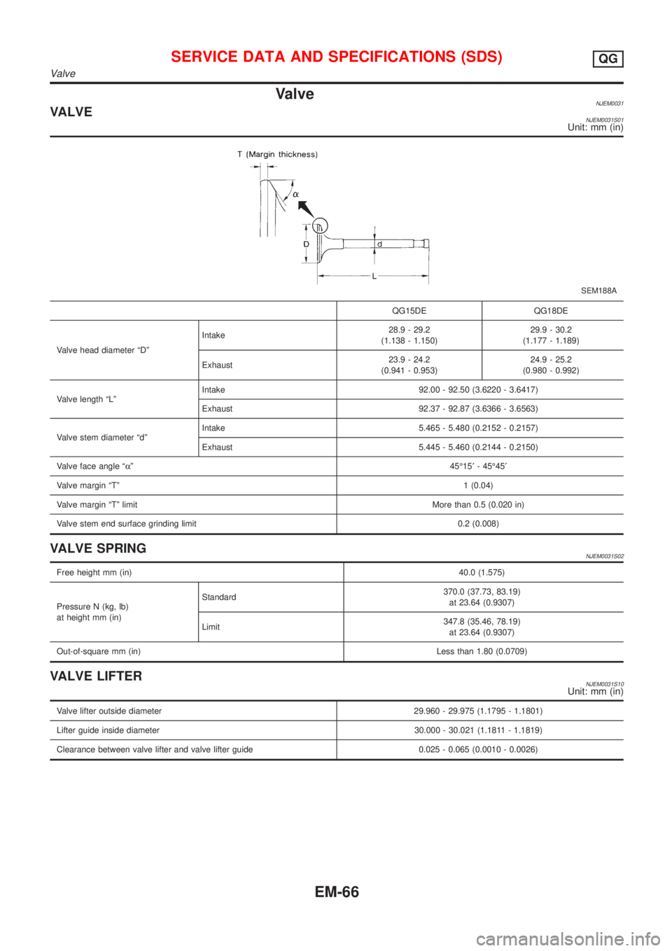
ValveNJEM0031VALVENJEM0031S01Unit: mm (in)
SEM188A
QG15DE QG18DE
Valve head diameter ªDºIntake28.9 - 29.2
(1.138 - 1.150)29.9 - 30.2
(1.177 - 1.189)
Exhaust23.9 - 24.2
(0.941 - 0.953)24.9 - 25.2
(0.980 - 0.992)
Valve length ªLºIntake 92.00 - 92.50 (3.6220 - 3.6417)
Exhaust 92.37 - 92.87 (3.6366 - 3.6563)
Valve stem diameter ªdºIntake 5.465 - 5.480 (0.2152 - 0.2157)
Exhaust 5.445 - 5.460 (0.2144 - 0.2150)
Valve face angle ªaº45É15¢- 45É45¢
Valve margin ªTº1 (0.04)
Valve margin ªTº limitMore than 0.5 (0.020 in)
Valve stem end surface grinding limit 0.2 (0.008)
VALVE SPRINGNJEM0031S02
Free height mm (in)40.0 (1.575)
Pressure N (kg, lb)
at height mm (in)Standard370.0 (37.73, 83.19)
at 23.64 (0.9307)
Limit347.8 (35.46, 78.19)
at 23.64 (0.9307)
Out-of-square mm (in)Less than 1.80 (0.0709)
VALVE LIFTERNJEM0031S10Unit: mm (in)
Valve lifter outside diameter 29.960 - 29.975 (1.1795 - 1.1801)
Lifter guide inside diameter 30.000 - 30.021 (1.1811 - 1.1819)
Clearance between valve lifter and valve lifter guide 0.025 - 0.065 (0.0010 - 0.0026)
SERVICE DATA AND SPECIFICATIONS (SDS)QG
Valve
EM-66
Page 145 of 2493

VALVE CLEARANCE=NJEM0031S11Unit: mm (in)
For adjusting For checking
Hot Cold* (reference data) Hot
Intake 0.32 - 0.40 (0.013 - 0.016) 0.25 - 0.33 (0.010 - 0.013) 0.21 - 0.49 (0.008 - 0.019)
Exhaust 0.37 - 0.45 (0.015 - 0.018) 0.32 - 0.40 (0.013 - 0.016) 0.30 - 0.58 (0.012 - 0.023)
*: At a temperature of approximately 20ÉC (68ÉF)
Whenever valve clearances are adjusted to cold specifications, check that the clearances satisfy hot specifications and adjust
again if necessary.
VALVE GUIDENJEM0031S04Unit: mm (in)
MEM096A
Intake Exhaust
Standard Service Standard Service
Valve guideOuter diameter9.523 - 9.534
(0.3749 - 0.3754)9.723 - 9.734
(0.3828 - 0.3832)9.523 - 9.534
(0.3749 - 0.3754)9.723 - 9.734
(0.3828 - 0.3832)
Inner diameter
[Finished size]5.500 - 5.515 (0.2165 - 0.2171) 5.500 - 5.515 (0.2165 - 0.2171)
Cylinder head valve guide hole diameter9.475 - 9.496
(0.3730 - 0.3739)9.685 - 9.696
(0.3813 - 0.3817)9.475 - 9.496
(0.3730 - 0.3739)9.685 - 9.696
(0.3813 - 0.3817)
Interference fit of valve guide0.027 - 0.059
(0.0011 - 0.0023)0.027 - 0.049
(0.0011 - 0.0019)0.027 - 0.059
(0.0011 - 0.0023)0.027 - 0.049
(0.0011 - 0.0019)
Stem to guide clearance 0.020 - 0.050 (0.0008 - 0.0020) 0.040 - 0.070 (0.0016 - 0.0028)
Valve deflection limit (Dial gauge reading) 0.2 (0.008)
Projection length ªLº 11.5 - 11.7 (0.453 - 0.461)
AVAILABLE SHIMSNJEM0031S07
Thickness mm (in) Identification mark
2.00 (0.0787) 200
2.02 (0.0795) 202
2.04 (0.0803) 204
2.06 (0.0811) 206
2.08 (0.0819) 208
2.10 (0.0827) 210
2.12 (0.0835) 212
2.14 (0.0843) 214
2.16 (0.0850) 216
SERVICE DATA AND SPECIFICATIONS (SDS)QG
Valve (Cont'd)
EM-67
Page 146 of 2493
2.18 (0.0858) 218
2.20 (0.0866) 220
2.21 (0.0870) 221
2.22 (0.0874) 222
2.23 (0.0878) 223
2.24 (0.0882) 224
2.25 (0.0886) 225
2.26 (0.0890) 226
2.27 (0.0895) 227
2.28 (0.0898) 228
2.29 (0.0902) 229
2.30 (0.0906) 230
2.31 (0.0909) 231
2.32 (0.0913) 232
2.33 (0.0917) 233
2.34 (0.0921) 234
2.35 (0.0925) 235
2.36 (0.0929) 236
2.37 (0.0933) 237
2.38 (0.0937) 238
2.39 (0.0941) 239
2.40 (0.0945) 240
2.41 (0.0949) 241
2.42 (0.0953) 242
2.43 (0.0957) 243
2.44 (0.0961) 244
2.45 (0.0965) 245
2.46 (0.0969) 246
2.47 (0.0972) 247
2.48 (0.0976) 248
2.49 (0.0980) 249
2.50 (0.0984) 250
2.51 (0.0988) 251
2.52 (0.0992) 252
2.53 (0.0966) 253
2.54 (0.1000) 254
2.55 (0.1004) 255
2.56 (0.1008) 256
2.57 (0.1012) 257
2.58 (0.1016) 258
2.59 (0.1020) 259
SERVICE DATA AND SPECIFICATIONS (SDS)QG
Valve (Cont'd)
EM-68