2001 NISSAN ALMERA N16 abs warning lamp
[x] Cancel search: abs warning lampPage 1780 of 2493
NOTE:
Stopping distance may be longer than vehicles without ABS when
road condition is slippery.
4. ABS Does Not WorkNJBR0107
1 CHECK WARNING LAMP INDICATION
Does the ABS warning lamp activate?
Ye s©Carry out self-diagnosis. Refer to BR-58.
No©Go to ª3. CHECK WARNING LAMP INDICATIONº in ª2. Unexpected Pedal Actionº,
BR-80.
NOTE:
ABS does not work when vehicle speed is under 10 km/h (6 MPH).
TROUBLE DIAGNOSES FOR SYMPTOMSABS
4. ABS Does Not Work
BR-82
Page 1781 of 2493
5. Pedal Vibration and Noise=NJBR0108
1 INSPECTION START
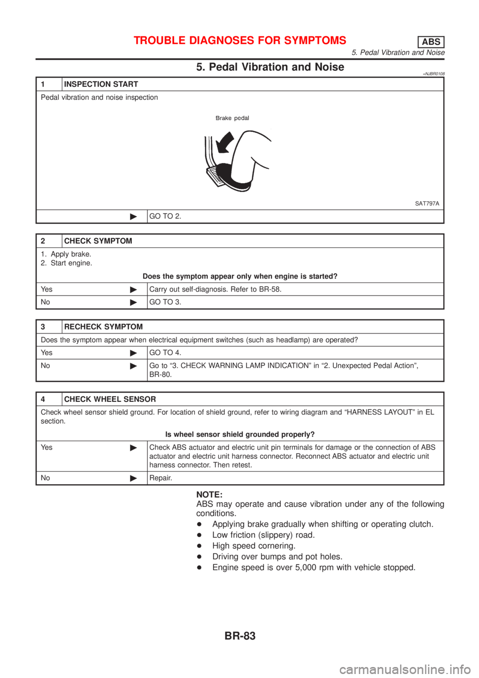
Pedal vibration and noise inspection
SAT797A
©GO TO 2.
2 CHECK SYMPTOM
1. Apply brake.
2. Start engine.
Does the symptom appear only when engine is started?
Ye s©Carry out self-diagnosis. Refer to BR-58.
No©GO TO 3.
3 RECHECK SYMPTOM
Does the symptom appear when electrical equipment switches (such as headlamp) are operated?
Ye s©GO TO 4.
No©Go to ª3. CHECK WARNING LAMP INDICATIONº in ª2. Unexpected Pedal Actionº,
BR-80.
4 CHECK WHEEL SENSOR
Check wheel sensor shield ground. For location of shield ground, refer to wiring diagram and ªHARNESS LAYOUTº in EL
section.
Is wheel sensor shield grounded properly?
Ye s©Check ABS actuator and electric unit pin terminals for damage or the connection of ABS
actuator and electric unit harness connector. Reconnect ABS actuator and electric unit
harness connector. Then retest.
No©Repair.
NOTE:
ABS may operate and cause vibration under any of the following
conditions.
+Applying brake gradually when shifting or operating clutch.
+Low friction (slippery) road.
+High speed cornering.
+Driving over bumps and pot holes.
+Engine speed is over 5,000 rpm with vehicle stopped.
TROUBLE DIAGNOSES FOR SYMPTOMSABS
5. Pedal Vibration and Noise
BR-83
Page 1782 of 2493
6. ABS Warning Lamp Does Not Come On
When Ignition Switch Is Turned On
=NJBR0109
1 INSPECTION START
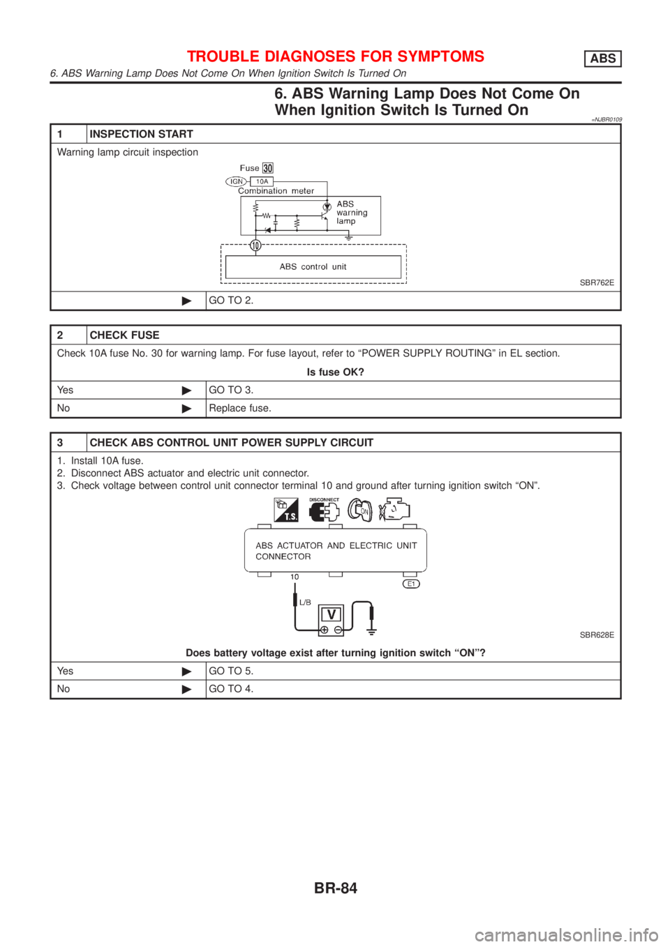
Warning lamp circuit inspection
SBR762E
©GO TO 2.
2 CHECK FUSE
Check 10A fuse No. 30 for warning lamp. For fuse layout, refer to ªPOWER SUPPLY ROUTINGº in EL section.
Is fuse OK?
Ye s©GO TO 3.
No©Replace fuse.
3 CHECK ABS CONTROL UNIT POWER SUPPLY CIRCUIT
1. Install 10A fuse.
2. Disconnect ABS actuator and electric unit connector.
3. Check voltage between control unit connector terminal 10 and ground after turning ignition switch ªONº.
SBR628E
Does battery voltage exist after turning ignition switch ªONº?
Ye s©GO TO 5.
No©GO TO 4.
TROUBLE DIAGNOSES FOR SYMPTOMSABS
6. ABS Warning Lamp Does Not Come On When Ignition Switch Is Turned On
BR-84
Page 1783 of 2493
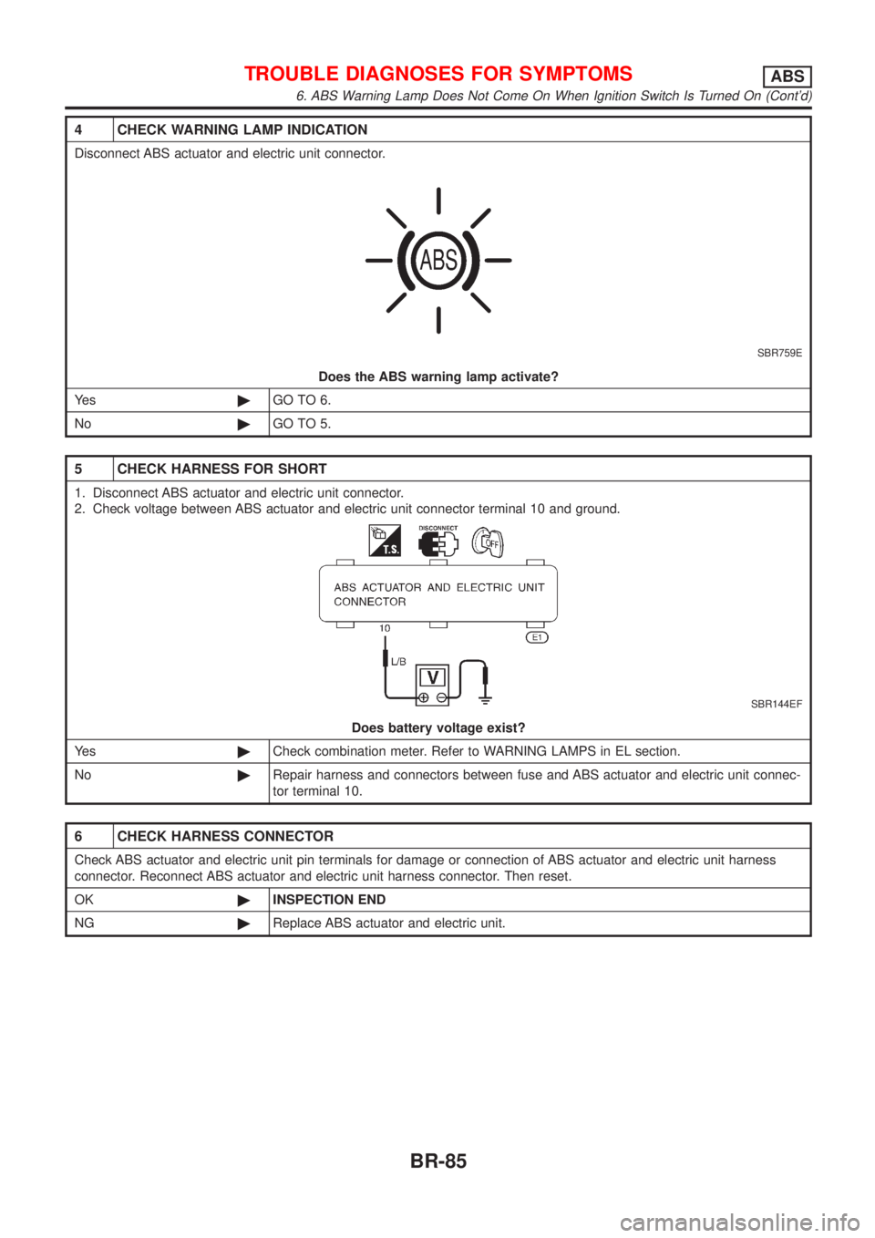
4 CHECK WARNING LAMP INDICATION
Disconnect ABS actuator and electric unit connector.
SBR759E
Does the ABS warning lamp activate?
Ye s©GO TO 6.
No©GO TO 5.
5 CHECK HARNESS FOR SHORT
1. Disconnect ABS actuator and electric unit connector.
2. Check voltage between ABS actuator and electric unit connector terminal 10 and ground.
SBR144EF
Does battery voltage exist?
Ye s©Check combination meter. Refer to WARNING LAMPS in EL section.
No©Repair harness and connectors between fuse and ABS actuator and electric unit connec-
tor terminal 10.
6 CHECK HARNESS CONNECTOR
Check ABS actuator and electric unit pin terminals for damage or connection of ABS actuator and electric unit harness
connector. Reconnect ABS actuator and electric unit harness connector. Then reset.
OK©INSPECTION END
NG©Replace ABS actuator and electric unit.
TROUBLE DIAGNOSES FOR SYMPTOMSABS
6. ABS Warning Lamp Does Not Come On When Ignition Switch Is Turned On (Cont'd)
BR-85
Page 1784 of 2493
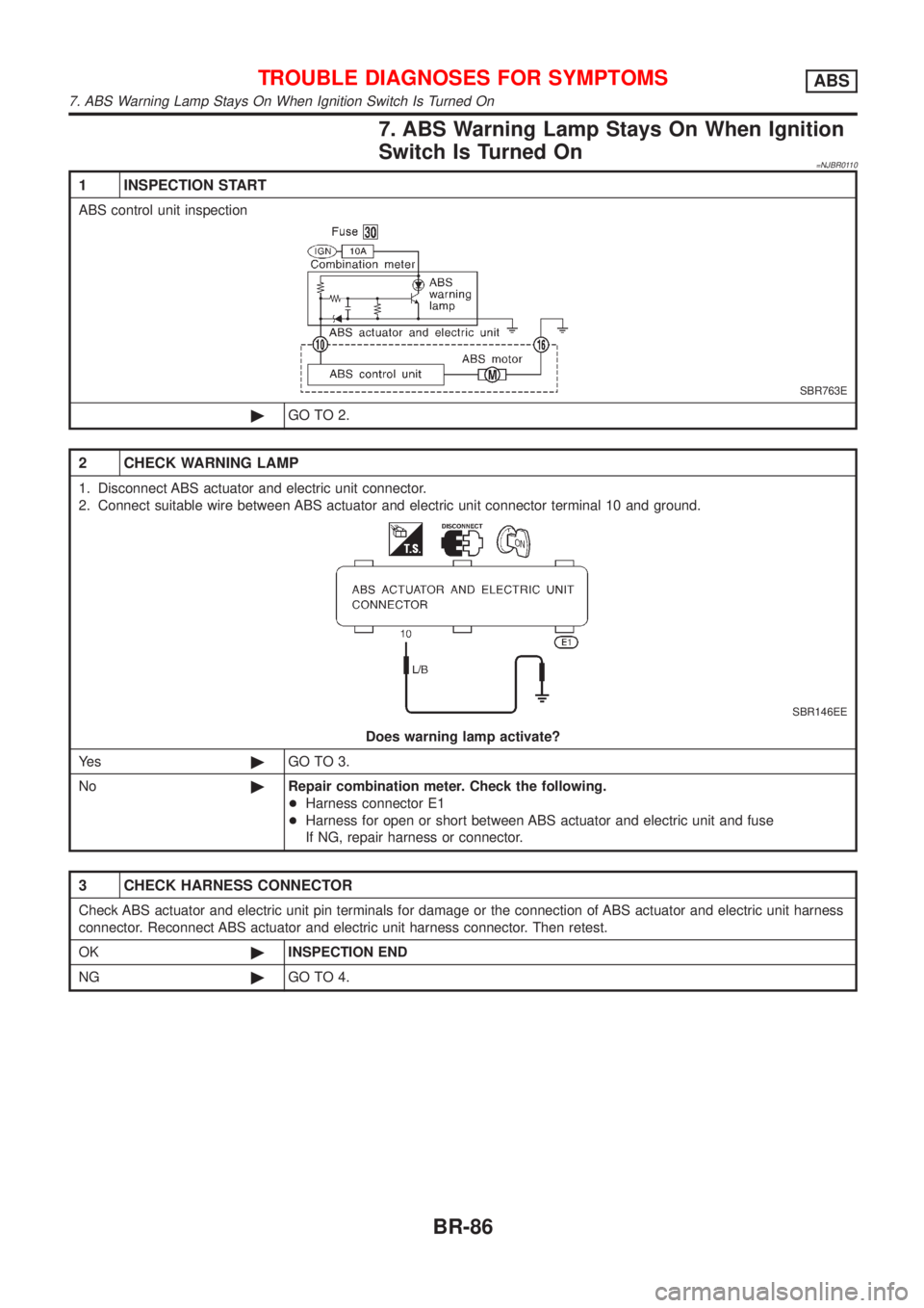
7. ABS Warning Lamp Stays On When Ignition
Switch Is Turned On
=NJBR0110
1 INSPECTION START
ABS control unit inspection
SBR763E
©GO TO 2.
2 CHECK WARNING LAMP
1. Disconnect ABS actuator and electric unit connector.
2. Connect suitable wire between ABS actuator and electric unit connector terminal 10 and ground.
SBR146EE
Does warning lamp activate?
Ye s©GO TO 3.
No©Repair combination meter. Check the following.
+Harness connector E1
+Harness for open or short between ABS actuator and electric unit and fuse
If NG, repair harness or connector.
3 CHECK HARNESS CONNECTOR
Check ABS actuator and electric unit pin terminals for damage or the connection of ABS actuator and electric unit harness
connector. Reconnect ABS actuator and electric unit harness connector. Then retest.
OK©INSPECTION END
NG©GO TO 4.
TROUBLE DIAGNOSES FOR SYMPTOMSABS
7. ABS Warning Lamp Stays On When Ignition Switch Is Turned On
BR-86
Page 1785 of 2493
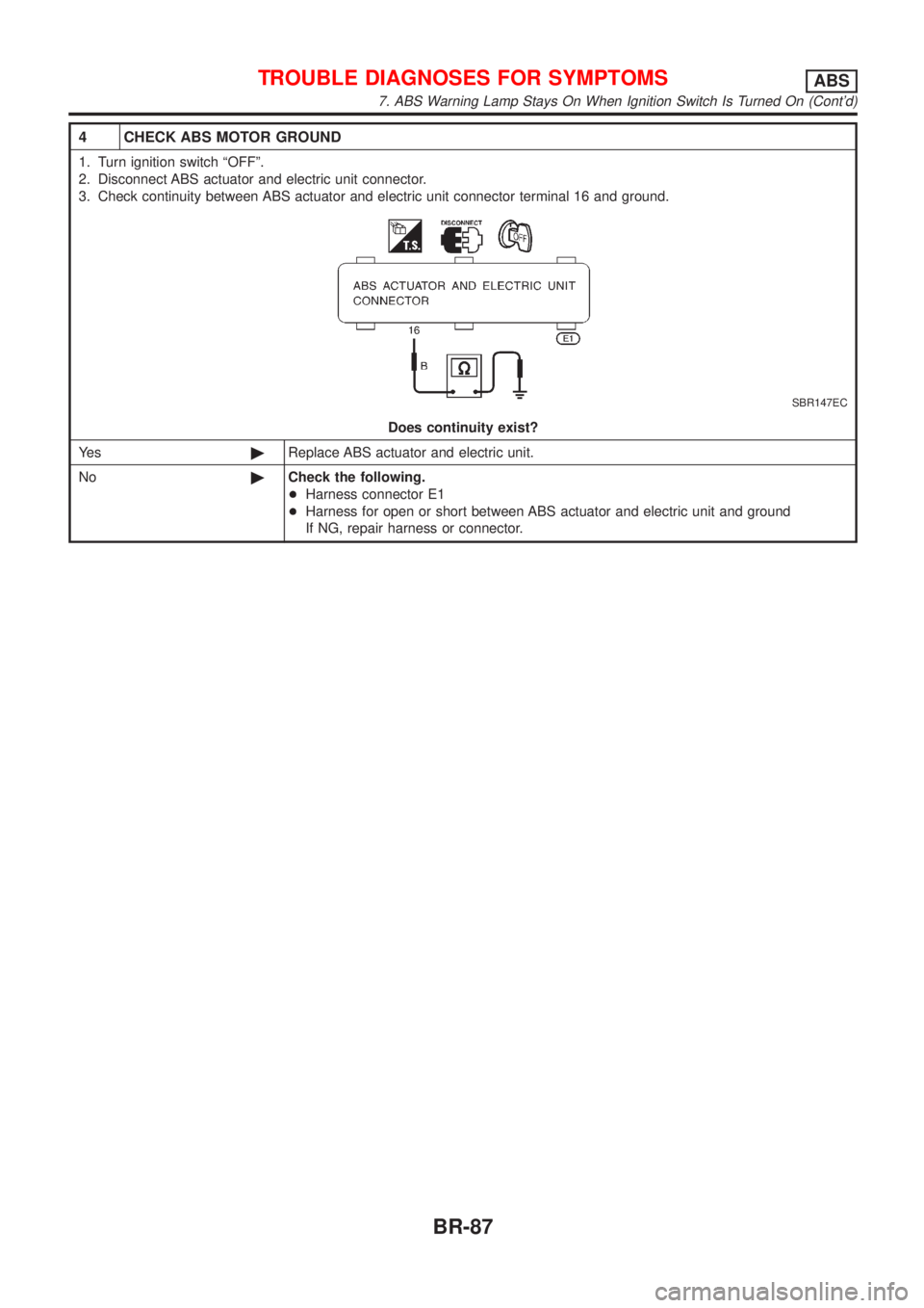
4 CHECK ABS MOTOR GROUND
1. Turn ignition switch ªOFFº.
2. Disconnect ABS actuator and electric unit connector.
3. Check continuity between ABS actuator and electric unit connector terminal 16 and ground.
SBR147EC
Does continuity exist?
Ye s©Replace ABS actuator and electric unit.
No©Check the following.
+Harness connector E1
+Harness for open or short between ABS actuator and electric unit and ground
If NG, repair harness or connector.
TROUBLE DIAGNOSES FOR SYMPTOMSABS
7. ABS Warning Lamp Stays On When Ignition Switch Is Turned On (Cont'd)
BR-87
Page 1974 of 2493
Supplemental Restraint System (SRS) ªAIR
BAGº and ªSEAT BELT PRE-TENSIONERº
NJHA0190The Supplemental Restraint System such as ªAIR BAGº and ªSEAT BELT PRE-TENSIONERº used along with
a seat belt, helps to reduce the risk or severity of injury to the driver and front passenger for certain types of
collision. The SRS system composition which is available to NISSAN MODEL N16 is as follows (The compo-
sition varies according to the destination and optional equipment.):
+For a frontal collision
The Supplemental Restraint System consists of driver air bag module (located in the center of the steer-
ing wheel), front passenger air bag module (located on the instrument panel on passenger side), front seat
belt pre-tensioners, a diagnosis sensor unit, warning lamp, wiring harness and spiral cable.
+For a side collision
The Supplemental Restraint System consists of front side air bag module (located in the outer side of front
seat), side air bag (satellite) sensor, diagnosis sensor unit (one of components of air bags for a frontal
collision), wiring harness, warning lamp (one of components of air bags for a frontal collision).
Information necessary to service the system safely is included in theRS sectionof this Service Manual.
WARNING:
+To avoid rendering the SRS inoperative, which could increase the risk of personal injury or death
in the event of a collision which would result in air bag inflation, all maintenance should be per-
formed by an authorized NISSAN dealer.
+Improper maintenance, including incorrect removal and installation of the SRS, can lead to per-
sonal injury caused by unintentional activation of the system. For removal of Spiral Cable and Air
Bag Module, see the RS section.
+Do not use electrical test equipment on any circuit related to the SRS unless instructed to in this
Service Manual. Spiral cable and wiring harnesses covered with yellow insulation tape either just
before the harness connectors or for the complete harness are related to the SRS.
Precautions for Working with HFC-134a
(R-134a)
NJHA0113WARNING:
+CFC-12 (R-12) refrigerant and HFC-134a (R-134a) refrigerant are not compatible. These refrigerants
must never be mixed, even in the smallest amounts. If the refrigerants are mixed, compressor fail-
ure is likely to occur.
+Use only specified lubricant for the HFC-134a (R-134a) A/C system and HFC-134a (R-134a) compo-
nents. If lubricant other than that specified is used, compressor failure is likely to occur.
+The specified HFC-134a (R-134a) lubricant rapidly absorbs moisture from the atmosphere. The fol-
lowing handling precautions must be observed:
a) When removing refrigerant components from a vehicle, immediately cap (seal) the component to
minimize the entry of moisture from the atmosphere.
b) When installing refrigerant components to a vehicle, do not remove the caps (unseal) until just
before connecting the components. Connect all refrigerant loop components as quickly as pos-
sible to minimize the entry of moisture into system.
c) Only use the specified lubricant from a sealed container. Immediately reseal containers of lubri-
cant. Without proper sealing, lubricant will become moisture saturated and should not be used.
d) Avoid breathing A/C refrigerant and lubricant vapor or mist. Exposure may irritate eyes, nose
and throat. Remove R-134a from the A/C system, using certified service equipment meeting
requirements of R-134a recycling equipment, or R-134a recovery equipment. If accidental system
discharge occurs, ventilate work area before resuming service. Additional health and safety
information may be obtained from refrigerant and lubricant manufacturers.
e) Do not allow lubricant (Nissan A/C System Oil Type S) to come in contact with styrofoam parts.
Damage may result.
General Refrigerant PrecautionsNJHA0114WARNING:
+Do not release refrigerant into the air. Use approved recovery/recycling equipment to capture the
refrigerant every time an air conditioning system is discharged.
+Always wear eye and hand protection (goggles and gloves) when working with any refrigerant or
air conditioning system.
PRECAUTIONS
Supplemental Restraint System (SRS) ªAIR BAGº and ªSEAT BELT PRE-TENSIONERº
HA-2
Page 2479 of 2493
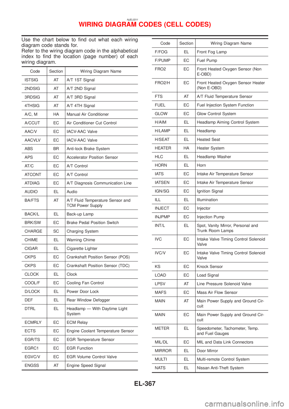
NJEL0311
Use the chart below to find out what each wiring
diagram code stands for.
Refer to the wiring diagram code in the alphabetical
index to find the location (page number) of each
wiring diagram.
Code Section Wiring Diagram Name
ISTSIG AT A/T 1ST Signal
2NDSIG AT A/T 2ND Signal
3RDSIG AT A/T 3RD Signal
4THSIG AT A/T 4TH Signal
A/C, M HA Manual Air Conditioner
A/CCUT EC Air Conditioner Cut Control
AAC/V EC IACV-AAC Valve
AACVLV EC IACV-AAC Valve
ABS BR Anti-lock Brake System
APS EC Accelerator Position Sensor
AT/C EC A/T Control
ATCONT EC A/T Control
ATDIAG EC A/T Diagnosis Communication Line
AUDIO EL Audio
BA/FTS AT A/T Fluid Temperature Sensor and
TCM Power Supply
BACK/L EL Back-up Lamp
BRK/SW EC Brake Pedal Position Switch
CHARGE SC Charging System
CHIME EL Warning Chime
CIGAR EL Cigarette Lighter
CKPS EC Crankshaft Position Sensor (POS)
CKPS EC Crankshaft Position Sensor (TDC)
CLOCK EL Clock
COOL/F EC Cooling Fan Control
D/LOCK EL Power Door Lock
DEF EL Rear Window Defogger
DTRL EL Headlamp Ð With Daytime Light
System
ECMRLY EC ECM Relay
ECTS EC Engine Coolant Temperature Sensor
EGR/TS EC EGR Temperature Sensor
EGRC1 EC EGR Function
EGVC/V EC EGR Volume Control Valve
ENGSS AT Engine Speed Signal
Code Section Wiring Diagram Name
F/FOG EL Front Fog Lamp
F/PUMP EC Fuel Pump
FRO2 EC Front Heated Oxygen Sensor (Non
E-OBD)
FRO2/H EC Front Heated Oxygen Sensor Heater
(Non E-OBD)
FTS AT A/T Fluid Temperature Sensor
FUEL EC Fuel Injection System Function
GLOW EC Glow Control System
H/AIM EL Headlamp Aiming Control System
H/LAMP EL Headlamp
H/SEAT EL Heated Seat
HEATER HA Heater System
HLC EL Headlamp Washer
HORN EL Horn
IATS EC Intake Air Temperature Sensor
IATSEN EC Intake Air Temperature Sensor
IGN/SG EC Ignition Signal
ILL EL Illumination
INJECT EC Injector
INJPMP EC Injection Pump
INT/L EL Spot, Vanity Mirror, Personal and
Trunk Room Lamps
IVC EC Intake Valve Timing Control Solenoid
Valve
IVC/V EC Intake Valve Timing Control Solenoid
Valve
KS EC Knock Sensor
LOAD EC Load Signal
LPSV AT Line Pressure Solenoid Valve
MAFS EC Mass Air Flow Sensor
MAIN AT Main Power Supply and Ground Cir-
cuit
MAIN EC Main Power Supply and Ground Cir-
cuit
METER EL Speedometer, Tachometer, Temp.
and Fuel Gauges
MIL/DL EC MIL and Data Link Connectors
MIRROR EL Door Mirror
MULTI EL Multi-remote Control System
NATS EL Nissan Anti-Theft System
WIRING DIAGRAM CODES (CELL CODES)
EL-367