2001 NISSAN ALMERA N16 Clutch
[x] Cancel search: ClutchPage 1643 of 2493

Bearing Retainer=NJAT0192SEAL RING CLEARANCENJAT0192S01Unit: mm (in)
Bearing retainer seal ring clearanceStandard 0.10 - 0.25 (0.0039 - 0.0098)
Allowable limit 0.25 (0.0098)
Total End PlayNJAT0193
Total end play ªT3º0.25 - 0.55 mm (0.0098 - 0.0217 in)
BEARING RACE FOR ADJUSTING TOTAL END PLAYNJAT0193S01
Thickness mm (in) Part number*
0.6 (0.024)
0.8 (0.031)
1.0 (0.039)
1.2 (0.047)
1.4 (0.055)
1.6 (0.063)
1.8 (0.071)
2.0 (0.079)31435-31X01
31435-31X02
31435-31X03
31435-31X04
31435-31X05
31435-31X06
31435-31X07
31435-31X08
*: Always check with the Parts Department for the latest parts information.
Reverse Clutch End PlayNJAT0194
Reverse clutch end play ªT4º 0.65 - 1.00 mm (0.0256 - 0.0394 in)
THRUST WASHERS FOR ADJUSTING REVERSE CLUTCH END PLAYNJAT0194S01
Thickness mm (in) Part number*
0.65 (0.0256)
0.80 (0.0315)
0.95 (0.0374)
1.10 (0.0433)
1.25 (0.0492)
1.40 (0.0551)31508-31X10
31508-31X11
31508-31X12
31508-31X13
31508-31X14
31508-31X15
*: Always check with the Parts Department for the latest parts information.
AccumulatorNJAT0195O-RINGNJAT0195S01Unit: mm (in)
Accumulator Diameter (Small) Part number* Diameter (Large) Part number*
Servo release accumulator 26.9 (1.059) 31526-41X03 44.2 (1.740) 31526-41X02
N-D accumulator 34.6 (1.362) 31526-31X08 39.4 (1.551) 31672-21X00
*: Always check with the Parts Department for the latest parts information.
RETURN SPRINGNJAT0195S02Unit: mm (in)
Accumulator Free length Outer diameter Part number*
Servo release accumulator springQG18DE + 3AX10, 3AX18 models 52.5 (2.067) 20.1 (0.791) 31605-80X00
Except QG18DE + 3AX10, 3AX18 mod-
els52.5 (2.067) 20.4 (0.803) 31605-80X03
N-D accumulator spring 45.0 (1.772) 27.6 (1.087) 31605-33X01
*: Always check with the Parts Department for the latest parts information.
SERVICE DATA AND SPECIFICATIONS (SDS)
Bearing Retainer
AT-457
Page 1644 of 2493
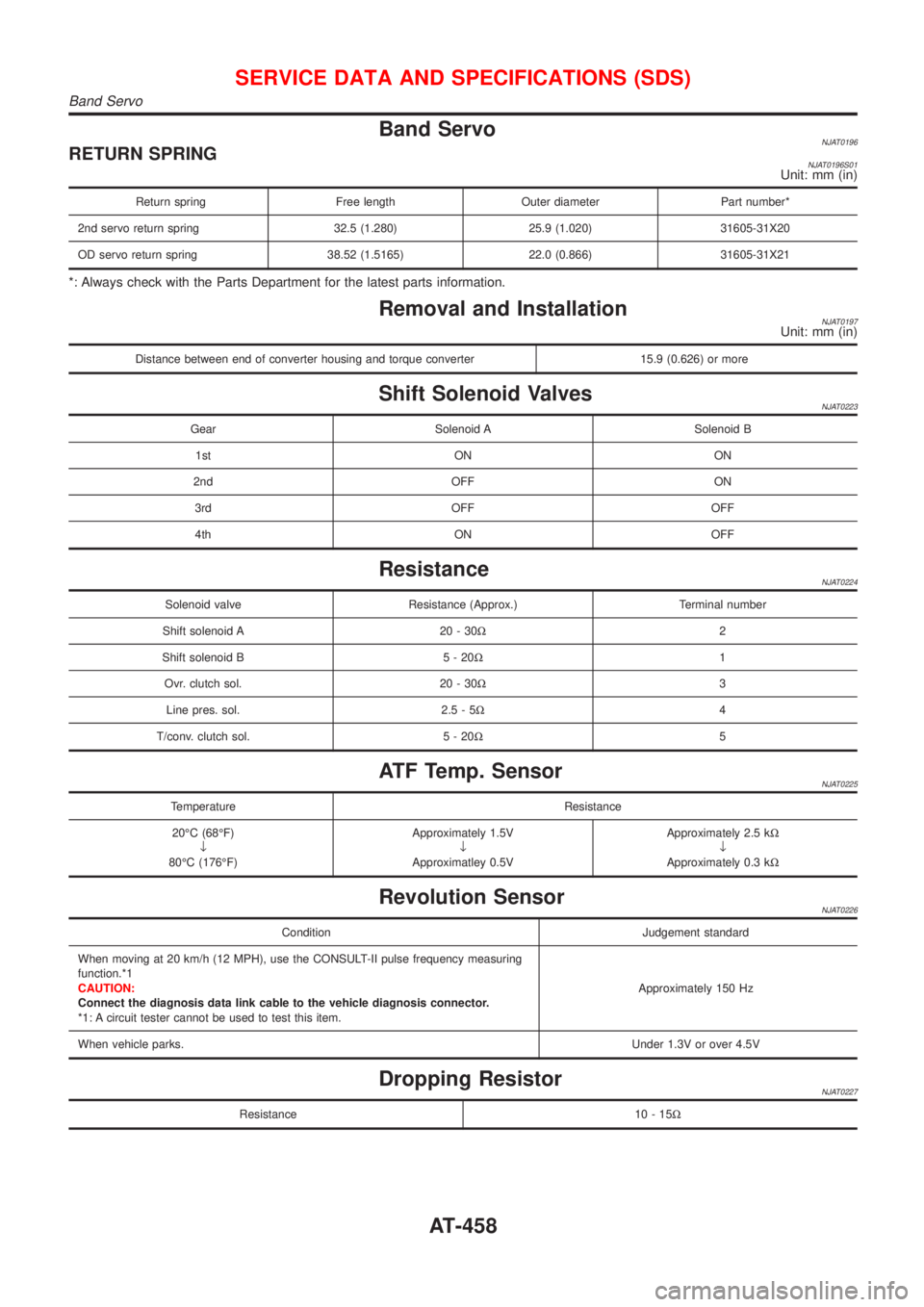
Band ServoNJAT0196RETURN SPRINGNJAT0196S01Unit: mm (in)
Return spring Free length Outer diameter Part number*
2nd servo return spring 32.5 (1.280) 25.9 (1.020) 31605-31X20
OD servo return spring 38.52 (1.5165) 22.0 (0.866) 31605-31X21
*: Always check with the Parts Department for the latest parts information.
Removal and InstallationNJAT0197Unit: mm (in)
Distance between end of converter housing and torque converter 15.9 (0.626) or more
Shift Solenoid ValvesNJAT0223
Gear Solenoid A Solenoid B
1st ON ON
2nd OFF ON
3rd OFF OFF
4th ON OFF
ResistanceNJAT0224
Solenoid valve Resistance (Approx.) Terminal number
Shift solenoid A 20 - 30W2
Shift solenoid B 5 - 20W1
Ovr. clutch sol. 20 - 30W3
Line pres. sol. 2.5 - 5W4
T/conv. clutch sol. 5 - 20W5
ATF Temp. SensorNJAT0225
Temperature Resistance
20ÉC (68ÉF)
¯
80ÉC (176ÉF)Approximately 1.5V
¯
Approximatley 0.5VApproximately 2.5 kW
¯
Approximately 0.3 kW
Revolution SensorNJAT0226
Condition Judgement standard
When moving at 20 km/h (12 MPH), use the CONSULT-II pulse frequency measuring
function.*1
CAUTION:
Connect the diagnosis data link cable to the vehicle diagnosis connector.
*1: A circuit tester cannot be used to test this item.Approximately 150 Hz
When vehicle parks.Under 1.3V or over 4.5V
Dropping ResistorNJAT0227
Resistance 10 - 15W
SERVICE DATA AND SPECIFICATIONS (SDS)
Band Servo
AT-458
Page 1781 of 2493
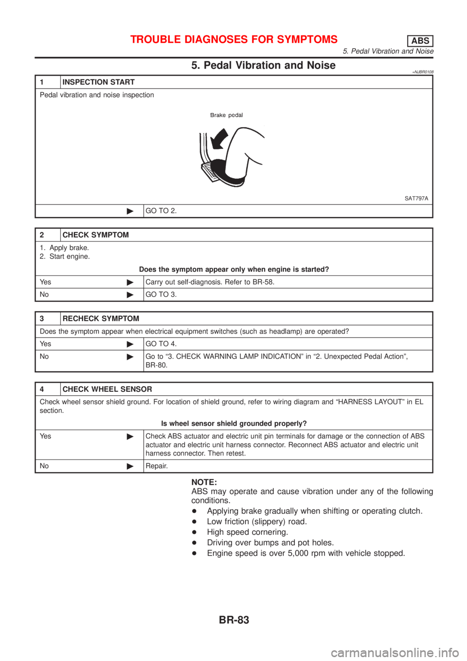
5. Pedal Vibration and Noise=NJBR0108
1 INSPECTION START
Pedal vibration and noise inspection
SAT797A
©GO TO 2.
2 CHECK SYMPTOM
1. Apply brake.
2. Start engine.
Does the symptom appear only when engine is started?
Ye s©Carry out self-diagnosis. Refer to BR-58.
No©GO TO 3.
3 RECHECK SYMPTOM
Does the symptom appear when electrical equipment switches (such as headlamp) are operated?
Ye s©GO TO 4.
No©Go to ª3. CHECK WARNING LAMP INDICATIONº in ª2. Unexpected Pedal Actionº,
BR-80.
4 CHECK WHEEL SENSOR
Check wheel sensor shield ground. For location of shield ground, refer to wiring diagram and ªHARNESS LAYOUTº in EL
section.
Is wheel sensor shield grounded properly?
Ye s©Check ABS actuator and electric unit pin terminals for damage or the connection of ABS
actuator and electric unit harness connector. Reconnect ABS actuator and electric unit
harness connector. Then retest.
No©Repair.
NOTE:
ABS may operate and cause vibration under any of the following
conditions.
+Applying brake gradually when shifting or operating clutch.
+Low friction (slippery) road.
+High speed cornering.
+Driving over bumps and pot holes.
+Engine speed is over 5,000 rpm with vehicle stopped.
TROUBLE DIAGNOSES FOR SYMPTOMSABS
5. Pedal Vibration and Noise
BR-83
Page 1973 of 2493
HEATER &
AIR CONDITIONER
SECTION
HA
CONTENTS
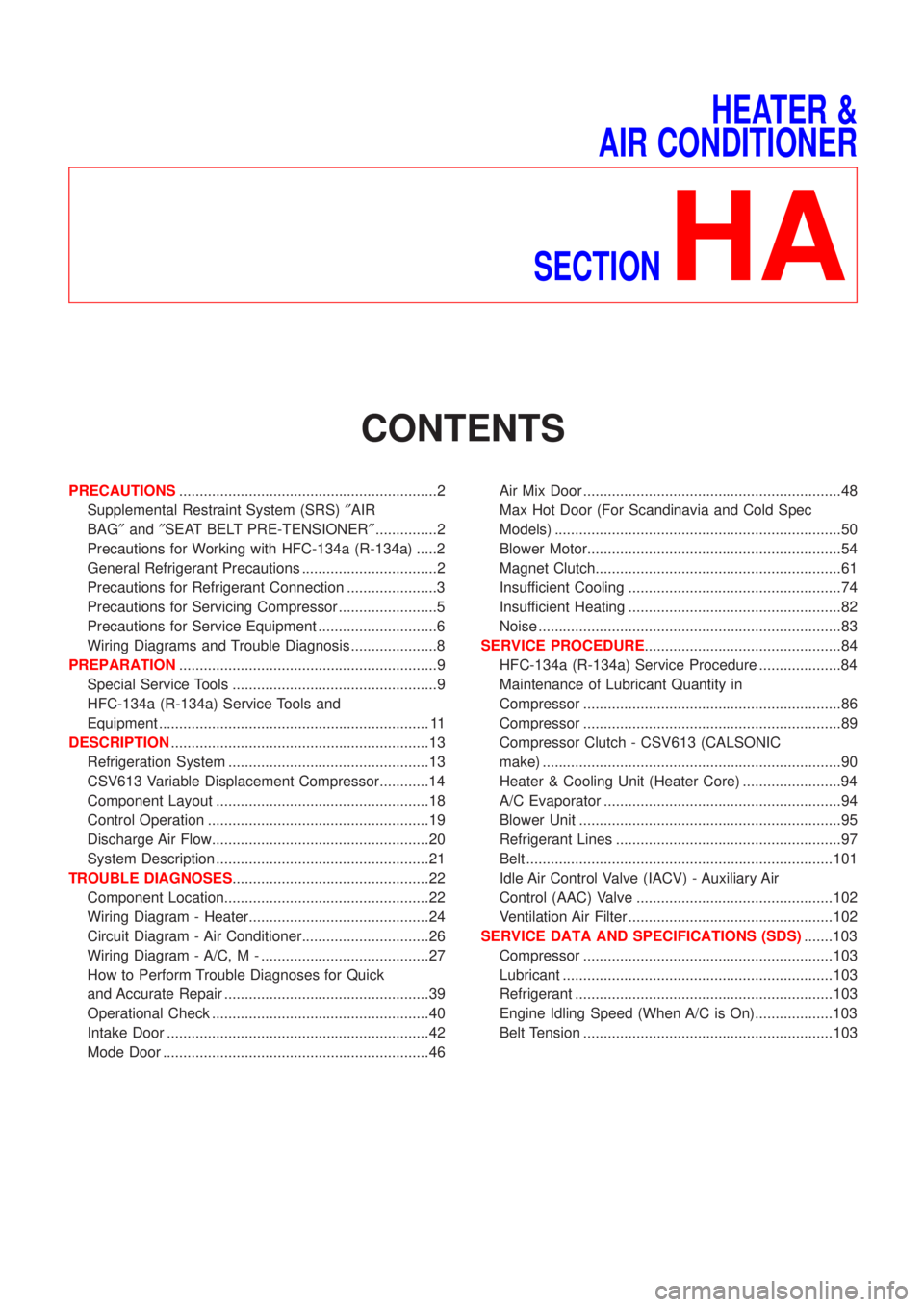
PRECAUTIONS...............................................................2
Supplemental Restraint System (SRS)²AIR
BAG²and²SEAT BELT PRE-TENSIONER²...............2
Precautions for Working with HFC-134a (R-134a) .....2
General Refrigerant Precautions .................................2
Precautions for Refrigerant Connection ......................3
Precautions for Servicing Compressor ........................5
Precautions for Service Equipment .............................6
Wiring Diagrams and Trouble Diagnosis .....................8
PREPARATION...............................................................9
Special Service Tools ..................................................9
HFC-134a (R-134a) Service Tools and
Equipment .................................................................. 11
DESCRIPTION...............................................................13
Refrigeration System .................................................13
CSV613 Variable Displacement Compressor............14
Component Layout ....................................................18
Control Operation ......................................................19
Discharge Air Flow.....................................................20
System Description ....................................................21
TROUBLE DIAGNOSES................................................22
Component Location..................................................22
Wiring Diagram - Heater............................................24
Circuit Diagram - Air Conditioner...............................26
Wiring Diagram - A/C, M - .........................................27
How to Perform Trouble Diagnoses for Quick
and Accurate Repair ..................................................39
Operational Check .....................................................40
Intake Door ................................................................42
Mode Door .................................................................46Air Mix Door ...............................................................48
Max Hot Door (For Scandinavia and Cold Spec
Models) ......................................................................50
Blower Motor..............................................................54
Magnet Clutch............................................................61
Insufficient Cooling ....................................................74
Insufficient Heating ....................................................82
Noise ..........................................................................83
SERVICE PROCEDURE................................................84
HFC-134a (R-134a) Service Procedure ....................84
Maintenance of Lubricant Quantity in
Compressor ...............................................................86
Compressor ...............................................................89
Compressor Clutch - CSV613 (CALSONIC
make) .........................................................................90
Heater & Cooling Unit (Heater Core) ........................94
A/C Evaporator ..........................................................94
Blower Unit ................................................................95
Refrigerant Lines .......................................................97
Belt ...........................................................................101
Idle Air Control Valve (IACV) - Auxiliary Air
Control (AAC) Valve ................................................102
Ventilation Air Filter ..................................................102
SERVICE DATA AND SPECIFICATIONS (SDS).......103
Compressor .............................................................103
Lubricant ..................................................................103
Refrigerant ...............................................................103
Engine Idling Speed (When A/C is On)...................103
Belt Tension .............................................................103
Page 1977 of 2493
+When installing an air conditioner in the vehicle, connect the pipes as the final stage of the opera-
tion. Do not remove the seal caps of pipes and other components until just before required for
connection.
+Allow components stored in cool areas to warm to working area temperature before removing seal
caps. This prevents condensation from forming inside A/C components.
+Thoroughly remove moisture from the refrigeration system before charging the refrigerant.
+Always replace used O-rings.
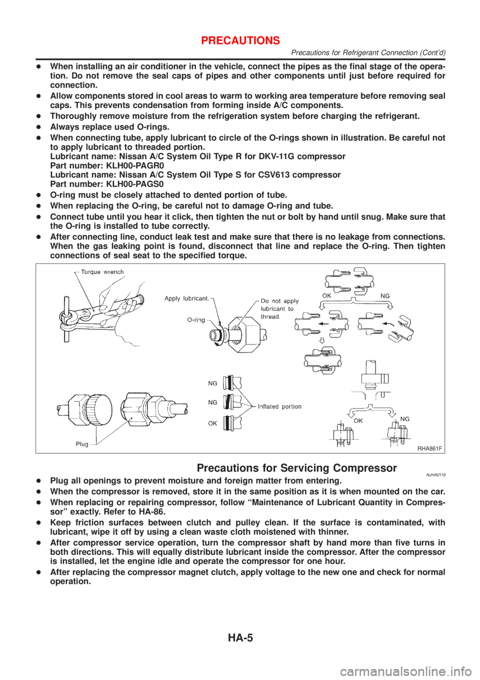
+When connecting tube, apply lubricant to circle of the O-rings shown in illustration. Be careful not
to apply lubricant to threaded portion.
Lubricant name: Nissan A/C System Oil Type R for DKV-11G compressor
Part number: KLH00-PAGR0
Lubricant name: Nissan A/C System Oil Type S for CSV613 compressor
Part number: KLH00-PAGS0
+O-ring must be closely attached to dented portion of tube.
+When replacing the O-ring, be careful not to damage O-ring and tube.
+Connect tube until you hear it click, then tighten the nut or bolt by hand until snug. Make sure that
the O-ring is installed to tube correctly.
+After connecting line, conduct leak test and make sure that there is no leakage from connections.
When the gas leaking point is found, disconnect that line and replace the O-ring. Then tighten
connections of seal seat to the specified torque.
RHA861F
Precautions for Servicing CompressorNJHA0116+Plug all openings to prevent moisture and foreign matter from entering.
+When the compressor is removed, store it in the same position as it is when mounted on the car.
+When replacing or repairing compressor, follow ªMaintenance of Lubricant Quantity in Compres-
sorº exactly. Refer to HA-86.
+Keep friction surfaces between clutch and pulley clean. If the surface is contaminated, with
lubricant, wipe it off by using a clean waste cloth moistened with thinner.
+After compressor service operation, turn the compressor shaft by hand more than five turns in
both directions. This will equally distribute lubricant inside the compressor. After the compressor
is installed, let the engine idle and operate the compressor for one hour.
+After replacing the compressor magnet clutch, apply voltage to the new one and check for normal
operation.
PRECAUTIONS
Precautions for Refrigerant Connection (Cont'd)
HA-5
Page 1981 of 2493
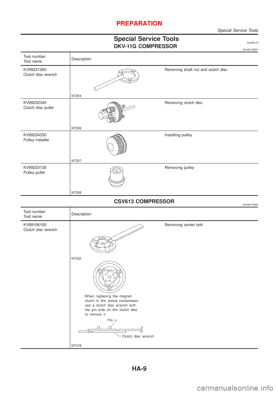
Special Service ToolsNJHA0119DKV-11G COMPRESSORNJHA0119S01
Tool number
Tool nameDescription
KV99231260
Clutch disc wrench
NT204
Removing shaft nut and clutch disc
KV99232340
Clutch disc puller
NT206
Removing clutch disc
KV99234330
Pulley installer
NT207
Installing pulley
KV99233130
Pulley puller
NT208
Removing pulley
CSV613 COMPRESSORNJHA0119S02
Tool number
Tool nameDescription
KV99106100
Clutch disc wrench
NT232
NT378
Removing center bolt
PREPARATION
Special Service Tools
HA-9
Page 1982 of 2493
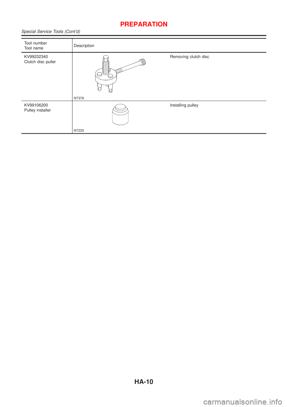
Tool number
Tool nameDescription
KV99232340
Clutch disc puller
NT376
Removing clutch disc
KV99106200
Pulley installer
NT235
Installing pulley
PREPARATION
Special Service Tools (Cont'd)
HA-10
Page 1986 of 2493
CSV613 Variable Displacement Compressor
GENERAL INFORMATIONNJHA02061. The CSV613 compressor differs from previous units. The vent temperatures of the CSV613 compressor
do not drop too far below 5ÉC (41ÉF) when:
+evaporator intake air temperature is less than 20ÉC (68ÉF)
+engine is running at speeds less than 1,500 rpm.
This is because the CSV613 compressor provides a means of ªcapacityº control.
2. The CSV613 compressor provides refrigerant control under varying conditions. During cold winters, it may
not produce high refrigerant pressure discharge (compared to previous units) when used with air condi-
tioning systems.
3. A ªclankingº sound may occasionally be heard during refrigerant charge. The sound indicates that the tilt
angle of the swash plate has changed and is not a problem.
4. For air conditioning systems with the CSV613 compressor, the clutch remains engaged unless: the sys-
tem main switch, fan switch or ignition switch is turned OFF. When ambient (outside) temperatures are
low or when the amount of refrigerant is insufficient, the clutch is disengaged to protect the compressor.
5. A constant range of suction pressure is maintained when engine speed is greater than a certain value. It
normally ranges from 147 to 177 kPa (1.47 to 1.77 bar, 1.5 to 1.8 kg/cm
2, 21 to 26 psi) under varying con-
ditions.
In previous compressors, however, suction pressure was reduced with increases in engine speed.
DESCRIPTION
CSV613 Variable Displacement Compressor
HA-14