2001 NISSAN ALMERA N16 Clutch
[x] Cancel search: ClutchPage 2063 of 2493
RHA136E
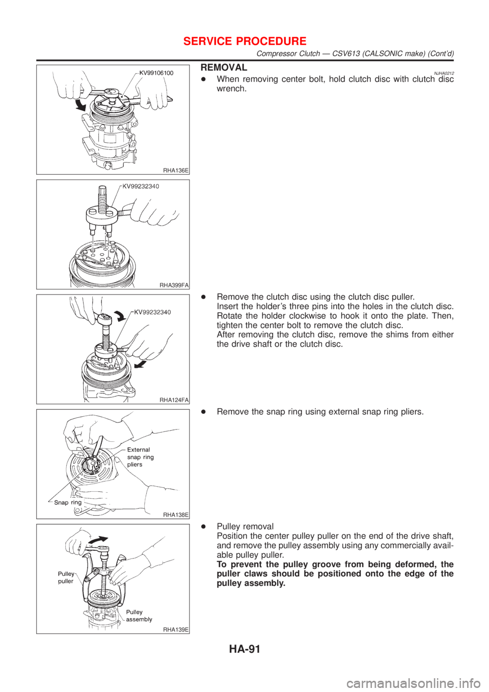
REMOVALNJHA0212+When removing center bolt, hold clutch disc with clutch disc
wrench.
RHA399FA
RHA124FA
+Remove the clutch disc using the clutch disc puller.
Insert the holder's three pins into the holes in the clutch disc.
Rotate the holder clockwise to hook it onto the plate. Then,
tighten the center bolt to remove the clutch disc.
After removing the clutch disc, remove the shims from either
the drive shaft or the clutch disc.
RHA138E
+Remove the snap ring using external snap ring pliers.
RHA139E
+Pulley removal
Position the center pulley puller on the end of the drive shaft,
and remove the pulley assembly using any commercially avail-
able pulley puller.
To prevent the pulley groove from being deformed, the
puller claws should be positioned onto the edge of the
pulley assembly.
SERVICE PROCEDURE
Compressor Clutch Ð CSV613 (CALSONIC make) (Cont'd)
HA-91
Page 2064 of 2493
RHA806H
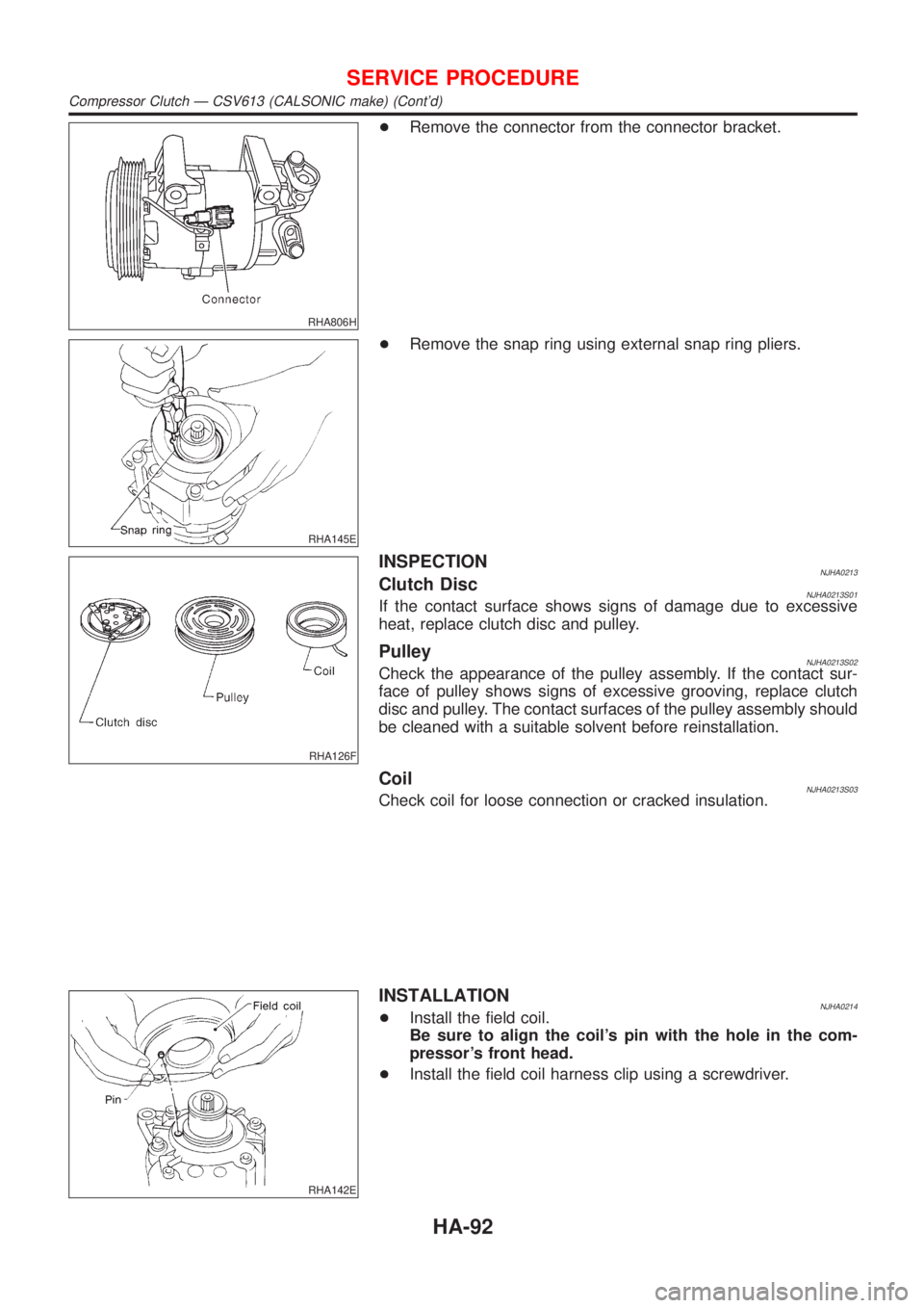
+Remove the connector from the connector bracket.
RHA145E
+Remove the snap ring using external snap ring pliers.
RHA126F
INSPECTIONNJHA0213Clutch DiscNJHA0213S01If the contact surface shows signs of damage due to excessive
heat, replace clutch disc and pulley.
PulleyNJHA0213S02Check the appearance of the pulley assembly. If the contact sur-
face of pulley shows signs of excessive grooving, replace clutch
disc and pulley. The contact surfaces of the pulley assembly should
be cleaned with a suitable solvent before reinstallation.
CoilNJHA0213S03Check coil for loose connection or cracked insulation.
RHA142E
INSTALLATIONNJHA0214+Install the field coil.
Be sure to align the coil's pin with the hole in the com-
pressor's front head.
+Install the field coil harness clip using a screwdriver.
SERVICE PROCEDURE
Compressor Clutch Ð CSV613 (CALSONIC make) (Cont'd)
HA-92
Page 2065 of 2493
RHA143E
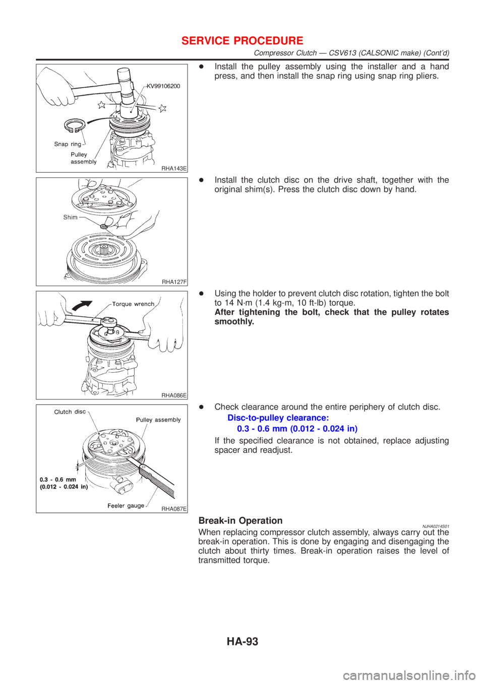
+Install the pulley assembly using the installer and a hand
press, and then install the snap ring using snap ring pliers.
RHA127F
+Install the clutch disc on the drive shaft, together with the
original shim(s). Press the clutch disc down by hand.
RHA086E
+Using the holder to prevent clutch disc rotation, tighten the bolt
to 14 N´m (1.4 kg-m, 10 ft-lb) torque.
After tightening the bolt, check that the pulley rotates
smoothly.
RHA087E
+Check clearance around the entire periphery of clutch disc.
Disc-to-pulley clearance:
0.3 - 0.6 mm (0.012 - 0.024 in)
If the specified clearance is not obtained, replace adjusting
spacer and readjust.
Break-in OperationNJHA0214S01When replacing compressor clutch assembly, always carry out the
break-in operation. This is done by engaging and disengaging the
clutch about thirty times. Break-in operation raises the level of
transmitted torque.
SERVICE PROCEDURE
Compressor Clutch Ð CSV613 (CALSONIC make) (Cont'd)
HA-93
Page 2077 of 2493
STARTING & CHARGING SYSTEMS
SECTION
SC
CONTENTS
PRECAUTIONS...............................................................2
Supplemental Restraint System (SRS)²AIR
BAG²and²SEAT BELT PRE-TENSIONER²...............2
Wiring Diagrams and Trouble Diagnoses....................2
BATTERY.........................................................................3
How to Handle Battery ................................................3
METHODS OF PREVENTING OVER-DISCHARGE......3
CHECKING ELECTROLYTE LEVEL............................3
SPECIFIC GRAVITY CHECK......................................4
Battery Test and Charging Chart .................................6
CHART I...................................................................6
CHART II..................................................................7
A: SLOW CHARGE....................................................8
B: STANDARD CHARGE..........................................10
C: QUICK CHARGE................................................. 11
STARTING SYSTEM.....................................................13
System Description ....................................................13
M/T MODELS..........................................................13
A/T MODELS...........................................................13
Wiring Diagram - START -.........................................14
Trouble Diagnoses.....................................................15
Construction ...............................................................16
Removal and Installation ...........................................19
REMOVAL...............................................................19
INSTALLATION........................................................19
Inspection...................................................................19
MAGNETIC SWITCH CHECK...................................19
PINION/CLUTCH CHECK.........................................19
BRUSH CHECK.......................................................20
YOKE CHECK.........................................................21
ARMATURE CHECK................................................21
Assembly ...................................................................22
PINION PROTRUSION LENGTH ADJUSTMENT........22
CHARGING SYSTEM....................................................24
System Description ....................................................24
Wiring Diagram - CHARGE -.....................................25
Trouble Diagnoses.....................................................26
WITH IC REGULATOR.............................................26
MALFUNCTION INDICATOR....................................26
Construction ...............................................................27
Removal and Installation ...........................................30
REMOVAL (QG ENGINE).........................................30
REMOVAL (YD ENGINE)..........................................30
INSTALLATION........................................................31
Disassembly...............................................................31
REAR COVER.........................................................31
REAR BEARING......................................................31
Inspection...................................................................31
ROTOR CHECK......................................................31
BRUSH CHECK.......................................................32
STATOR CHECK.....................................................32
Assembly ...................................................................32
RING FITTING IN REAR BEARING...........................32
REAR COVER INSTALLATION.................................33
SERVICE DATA AND SPECIFICATIONS (SDS).........34
Battery........................................................................34
Starter ........................................................................34
Alternator ...................................................................35
Page 2095 of 2493
SEL909TA
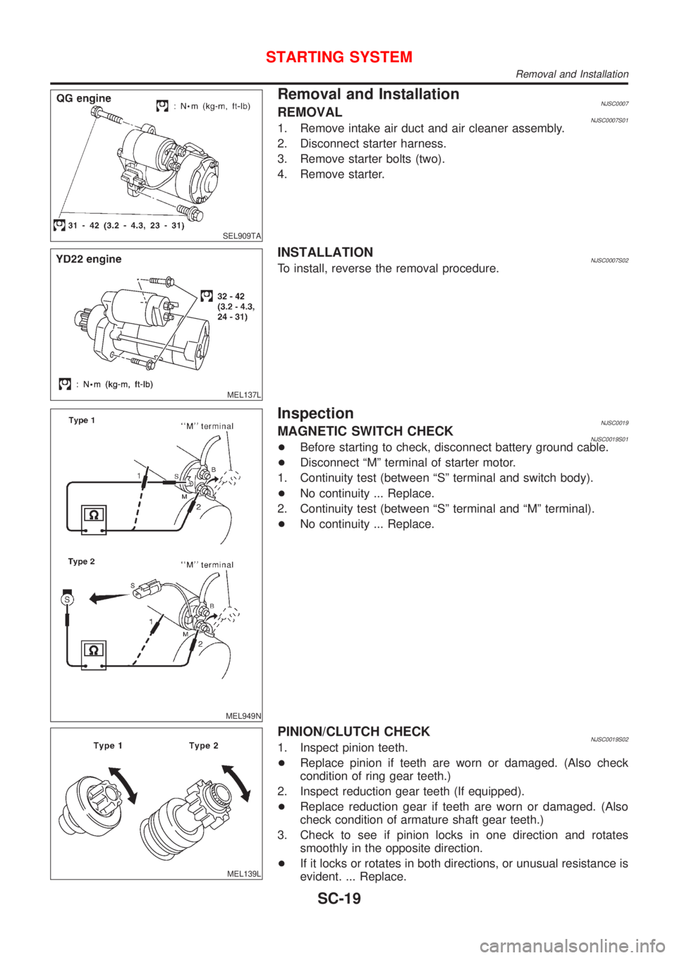
Removal and InstallationNJSC0007REMOVALNJSC0007S011. Remove intake air duct and air cleaner assembly.
2. Disconnect starter harness.
3. Remove starter bolts (two).
4. Remove starter.
MEL137L
INSTALLATIONNJSC0007S02To install, reverse the removal procedure.
MEL949N
InspectionNJSC0019MAGNETIC SWITCH CHECKNJSC0019S01+Before starting to check, disconnect battery ground cable.
+Disconnect ªMº terminal of starter motor.
1. Continuity test (between ªSº terminal and switch body).
+No continuity ... Replace.
2. Continuity test (between ªSº terminal and ªMº terminal).
+No continuity ... Replace.
MEL139L
PINION/CLUTCH CHECKNJSC0019S021. Inspect pinion teeth.
+Replace pinion if teeth are worn or damaged. (Also check
condition of ring gear teeth.)
2. Inspect reduction gear teeth (If equipped).
+Replace reduction gear if teeth are worn or damaged. (Also
check condition of armature shaft gear teeth.)
3. Check to see if pinion locks in one direction and rotates
smoothly in the opposite direction.
+If it locks or rotates in both directions, or unusual resistance is
evident. ... Replace.
STARTING SYSTEM
Removal and Installation
SC-19
Page 2480 of 2493
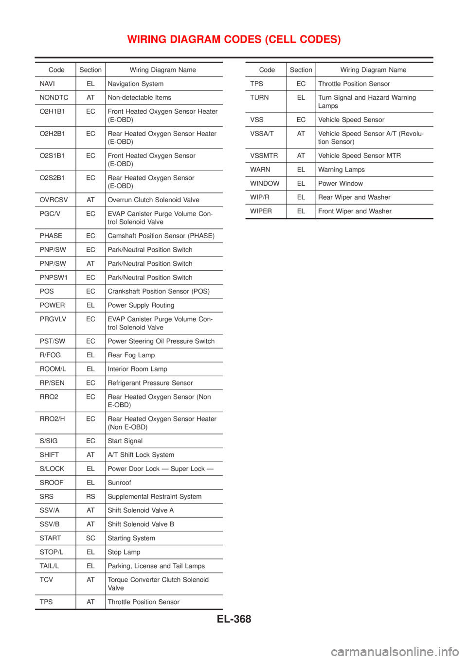
Code Section Wiring Diagram Name
NAVI EL Navigation System
NONDTC AT Non-detectable Items
O2H1B1 EC Front Heated Oxygen Sensor Heater
(E-OBD)
O2H2B1 EC Rear Heated Oxygen Sensor Heater
(E-OBD)
O2S1B1 EC Front Heated Oxygen Sensor
(E-OBD)
O2S2B1 EC Rear Heated Oxygen Sensor
(E-OBD)
OVRCSV AT Overrun Clutch Solenoid Valve
PGC/V EC EVAP Canister Purge Volume Con-
trol Solenoid Valve
PHASE EC Camshaft Position Sensor (PHASE)
PNP/SW EC Park/Neutral Position Switch
PNP/SW AT Park/Neutral Position Switch
PNPSW1 EC Park/Neutral Position Switch
POS EC Crankshaft Position Sensor (POS)
POWER EL Power Supply Routing
PRGVLV EC EVAP Canister Purge Volume Con-
trol Solenoid Valve
PST/SW EC Power Steering Oil Pressure Switch
R/FOG EL Rear Fog Lamp
ROOM/L EL Interior Room Lamp
RP/SEN EC Refrigerant Pressure Sensor
RRO2 EC Rear Heated Oxygen Sensor (Non
E-OBD)
RRO2/H EC Rear Heated Oxygen Sensor Heater
(Non E-OBD)
S/SIG EC Start Signal
SHIFT AT A/T Shift Lock System
S/LOCK EL Power Door Lock Ð Super Lock Ð
SROOF EL Sunroof
SRS RS Supplemental Restraint System
SSV/A AT Shift Solenoid Valve A
SSV/B AT Shift Solenoid Valve B
START SC Starting System
STOP/L EL Stop Lamp
TAIL/L EL Parking, License and Tail Lamps
TCV AT Torque Converter Clutch Solenoid
Valve
TPS AT Throttle Position SensorCode Section Wiring Diagram Name
TPS EC Throttle Position Sensor
TURN EL Turn Signal and Hazard Warning
Lamps
VSS EC Vehicle Speed Sensor
VSSA/T AT Vehicle Speed Sensor A/T (Revolu-
tion Sensor)
VSSMTR AT Vehicle Speed Sensor MTR
WARN EL Warning Lamps
WINDOW EL Power Window
WIP/R EL Rear Wiper and Washer
WIPER EL Front Wiper and Washer
WIRING DIAGRAM CODES (CELL CODES)
EL-368
Page 2482 of 2493
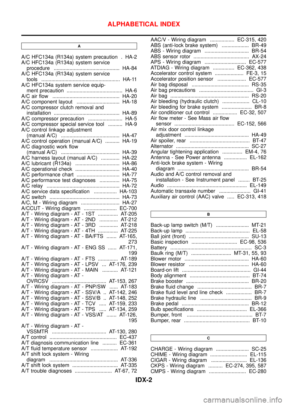
A
A/C HFC134a (R134a) system precaution . HA-2
A/C HFC134a (R134a) system service
procedure .............................................. HA-84
A/C HFC134a (R134a) system service
tools ....................................................... HA-11
A/C HFC134a system service equip-
ment precaution ....................................... HA-6
A/C air flow ............................................... HA-20
A/C component layout .............................. HA-18
A/C compressor clutch removal and
installation .............................................. HA-89
A/C compressor precaution ........................ HA-5
A/C compressor special service tool .......... HA-9
A/C control linkage adjustment
(manual A/C) ......................................... HA-47
A/C control operation (manual A/C) .......... HA-19
A/C diagnostic work flow
(manual A/C) ......................................... HA-39
A/C harness layout (manual A/C) ............. HA-22
A/C lubricant (R134a) ............................... HA-86
A/C operational check ............................... HA-40
A/C performance chart .............................. HA-77
A/C performance test diagnoses .............. HA-75
A/C relay ................................................... HA-72
A/C service data specification ................ HA-103
A/C switch ................................................. HA-73
A/C, M - Wiring diagram ........................... HA-27
A/CCUT - Wiring diagram ....................... EC-700
A/T - Wiring diagram - AT - 1ST .............. AT-205
A/T - Wiring diagram - AT - 2ND ............. AT-212
A/T - Wiring diagram - AT - 3RD ............. AT-218
A/T - Wiring diagram - AT - 4TH .............. AT-225
A/T - Wiring diagram - AT - BA/FTS ....... AT-165,
273
A/T - Wiring diagram - AT - ENG SS ...... AT-171,
199
A/T - Wiring diagram - AT - FTS .............. AT-189
A/T - Wiring diagram - AT - LPSV ... AT-176, 239
A/T - Wiring diagram - AT - MAIN ........... AT-121
A/T - Wiring diagram - AT -
OVRCSV ...................................... AT-153, 267
A/T - Wiring diagram - AT - PNP/SW ...... AT-183
A/T - Wiring diagram - AT - SSV/A .. AT-142, 246
A/T - Wiring diagram - AT - SSV/B .. AT-148, 252
A/T - Wiring diagram - AT - TCV ..... AT-159, 233
A/T - Wiring diagram - AT - TPS ..... AT-134, 259
A/T - Wiring diagram - AT - VSS/AT ....... AT-126,
195
A/T - Wiring diagram - AT -
VSSMTR ...................................... AT-130, 280
A/T control ............................................... EC-437
A/T diagnosis communication line .......... EC-361
A/T fluid temperature sensor ................... AT-192
A/T shift lock system - Wiring
diagram ................................................ AT-336
A/T shift lock system ................................ AT-335
A/T trouble diagnoses .......................... AT-67, 72AAC/V - Wiring diagram ................. EC-315, 420
ABS (anti-lock brake system) ................... BR-49
ABS - Wiring diagram ............................... BR-54
ABS sensor rotor ....................................... AX-24
APS - Wiring diagram ............................. EC-577
ATDIAG - Wiring diagram ............... EC-362, 438
Accelerator control system .................... FE-3, 15
Accelerator position sensor .................... EC-577
Air bag disposal ........................................ RS-35
Air bag precautions ...................................... GI-3
Air bag ....................................................... RS-20
Air bleeding (hydraulic clutch) ................... CL-10
Air bleeding for brake system ..................... BR-8
Air conditioner cut control ................. EC-32, 507
Air flow meter - See Mass air flow
sensor .......................................... EC-152, 566
Air mix door control linkage
adjustment ............................................. HA-49
Air spoiler, rear .......................................... BT-47
Alternator ................................................... SC-27
Angular tightening application .............. EM-4, 76
Antenna - See Power antenna ................ EL-162
Anti-lock brake system - Wiring
diagram .................................................. BR-54
Audio and A/C control removal and
installation - See Instrument panel ........ BT-25
Audio ........................................................ EL-149
Automatic transaxle number ...................... GI-41
Auxiliary air control (AAC) valve ..... EC-313, 418
B
Back-up lamp switch (M/T) ....................... MT-21
Back-up lamp ............................................. EL-58
Ball joint (front) .......................................... SU-13
Basic inspection ................................ EC-98, 536
Battery ......................................................... SC-3
Baulk ring (M/T) ............................ MT-31, 55, 93
Blower motor ............................................. HA-60
Blower resistor .......................................... HA-60
Board-on lift ................................................ GI-44
Body alignment .......................................... BT-74
Brake booster ............................................ BR-20
Brake fluid change ...................................... BR-7
Brake fluid level and line check .................. BR-7
Brake hydraulic line .................................... BR-9
Brake pedal ............................................... BR-12
Bulb specifications ................................... EL-366
Bumper, front .............................................. BT-7
Bumper, rear .............................................. BT-10
C
CHARGE - Wiring diagram ....................... SC-25
CHIME - Wiring diagram .......................... EL-115
CIGAR - Wiring diagram ......................... EL-136
CKPS - Wiring diagram .......... EC-274, 395, 587
CMPS - Wiring diagram .......................... EC-280
ALPHABETICAL INDEX
IDX-2
Page 2483 of 2493
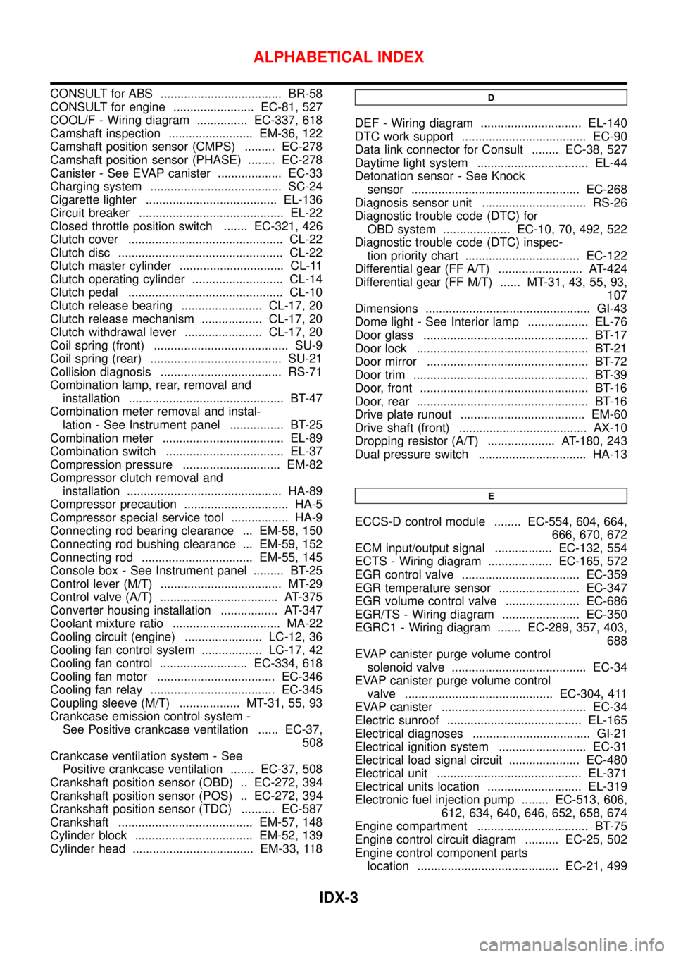
CONSULT for ABS .................................... BR-58
CONSULT for engine ........................ EC-81, 527
COOL/F - Wiring diagram ............... EC-337, 618
Camshaft inspection ......................... EM-36, 122
Camshaft position sensor (CMPS) ......... EC-278
Camshaft position sensor (PHASE) ........ EC-278
Canister - See EVAP canister ................... EC-33
Charging system ....................................... SC-24
Cigarette lighter ....................................... EL-136
Circuit breaker ........................................... EL-22
Closed throttle position switch ....... EC-321, 426
Clutch cover .............................................. CL-22
Clutch disc ................................................. CL-22
Clutch master cylinder ............................... CL-11
Clutch operating cylinder ........................... CL-14
Clutch pedal .............................................. CL-10
Clutch release bearing ........................ CL-17, 20
Clutch release mechanism .................. CL-17, 20
Clutch withdrawal lever ....................... CL-17, 20
Coil spring (front) ........................................ SU-9
Coil spring (rear) ....................................... SU-21
Collision diagnosis .................................... RS-71
Combination lamp, rear, removal and
installation .............................................. BT-47
Combination meter removal and instal-
lation - See Instrument panel ................ BT-25
Combination meter .................................... EL-89
Combination switch ................................... EL-37
Compression pressure ............................. EM-82
Compressor clutch removal and
installation .............................................. HA-89
Compressor precaution ............................... HA-5
Compressor special service tool ................. HA-9
Connecting rod bearing clearance ... EM-58, 150
Connecting rod bushing clearance ... EM-59, 152
Connecting rod ................................. EM-55, 145
Console box - See Instrument panel ......... BT-25
Control lever (M/T) .................................... MT-29
Control valve (A/T) ................................... AT-375
Converter housing installation ................. AT-347
Coolant mixture ratio ................................ MA-22
Cooling circuit (engine) ....................... LC-12, 36
Cooling fan control system .................. LC-17, 42
Cooling fan control .......................... EC-334, 618
Cooling fan motor ................................... EC-346
Cooling fan relay ..................................... EC-345
Coupling sleeve (M/T) .................. MT-31, 55, 93
Crankcase emission control system -
See Positive crankcase ventilation ...... EC-37,
508
Crankcase ventilation system - See
Positive crankcase ventilation ....... EC-37, 508
Crankshaft position sensor (OBD) .. EC-272, 394
Crankshaft position sensor (POS) .. EC-272, 394
Crankshaft position sensor (TDC) .......... EC-587
Crankshaft ........................................ EM-57, 148
Cylinder block ................................... EM-52, 139
Cylinder head .................................... EM-33, 118D
DEF - Wiring diagram .............................. EL-140
DTC work support ..................................... EC-90
Data link connector for Consult ........ EC-38, 527
Daytime light system ................................. EL-44
Detonation sensor - See Knock
sensor .................................................. EC-268
Diagnosis sensor unit ............................... RS-26
Diagnostic trouble code (DTC) for
OBD system .................... EC-10, 70, 492, 522
Diagnostic trouble code (DTC) inspec-
tion priority chart .................................. EC-122
Differential gear (FF A/T) ......................... AT-424
Differential gear (FF M/T) ...... MT-31, 43, 55, 93,
107
Dimensions ................................................. GI-43
Dome light - See Interior lamp .................. EL-76
Door glass ................................................. BT-17
Door lock ................................................... BT-21
Door mirror ................................................ BT-72
Door trim .................................................... BT-39
Door, front .................................................. BT-16
Door, rear ................................................... BT-16
Drive plate runout ..................................... EM-60
Drive shaft (front) ...................................... AX-10
Dropping resistor (A/T) .................... AT-180, 243
Dual pressure switch ................................ HA-13
E
ECCS-D control module ........ EC-554, 604, 664,
666, 670, 672
ECM input/output signal ................. EC-132, 554
ECTS - Wiring diagram ................... EC-165, 572
EGR control valve ................................... EC-359
EGR temperature sensor ........................ EC-347
EGR volume control valve ...................... EC-686
EGR/TS - Wiring diagram ....................... EC-350
EGRC1 - Wiring diagram ....... EC-289, 357, 403,
688
EVAP canister purge volume control
solenoid valve ........................................ EC-34
EVAP canister purge volume control
valve ............................................ EC-304, 411
EVAP canister ........................................... EC-34
Electric sunroof ........................................ EL-165
Electrical diagnoses ................................... GI-21
Electrical ignition system .......................... EC-31
Electrical load signal circuit ..................... EC-480
Electrical unit ........................................... EL-371
Electrical units location ............................ EL-319
Electronic fuel injection pump ........ EC-513, 606,
612, 634, 640, 646, 652, 658, 674
Engine compartment ................................. BT-75
Engine control circuit diagram .......... EC-25, 502
Engine control component parts
location .......................................... EC-21, 499
ALPHABETICAL INDEX
IDX-3