Page 660 of 2493
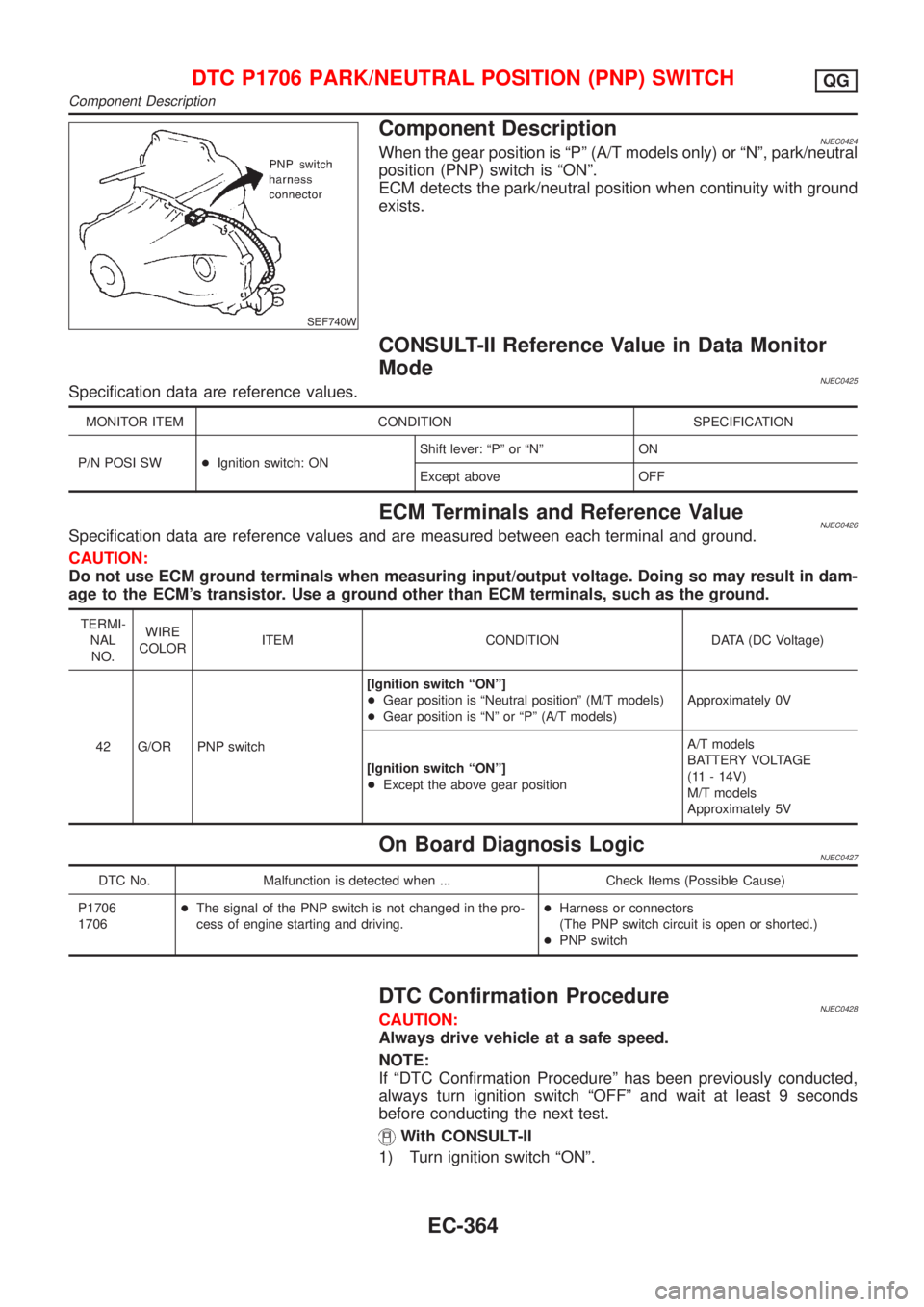
SEF740W
Component DescriptionNJEC0424When the gear position is ªPº (A/T models only) or ªNº, park/neutral
position (PNP) switch is ªONº.
ECM detects the park/neutral position when continuity with ground
exists.
CONSULT-II Reference Value in Data Monitor
Mode
NJEC0425Specification data are reference values.
MONITOR ITEM CONDITION SPECIFICATION
P/N POSI SW+Ignition switch: ONShift lever: ªPº or ªNº ON
Except above OFF
ECM Terminals and Reference ValueNJEC0426Specification data are reference values and are measured between each terminal and ground.
CAUTION:
Do not use ECM ground terminals when measuring input/output voltage. Doing so may result in dam-
age to the ECM's transistor. Use a ground other than ECM terminals, such as the ground.
TERMI-
NAL
NO.WIRE
COLORITEM CONDITION DATA (DC Voltage)
42 G/OR PNP switch[Ignition switch ªONº]
+Gear position is ªNeutral positionº (M/T models)
+Gear position is ªNº or ªPº (A/T models)Approximately 0V
[Ignition switch ªONº]
+Except the above gear positionA/T models
BATTERY VOLTAGE
(11 - 14V)
M/T models
Approximately 5V
On Board Diagnosis LogicNJEC0427
DTC No. Malfunction is detected when ... Check Items (Possible Cause)
P1706
1706+The signal of the PNP switch is not changed in the pro-
cess of engine starting and driving.+Harness or connectors
(The PNP switch circuit is open or shorted.)
+PNP switch
DTC Confirmation ProcedureNJEC0428CAUTION:
Always drive vehicle at a safe speed.
NOTE:
If ªDTC Confirmation Procedureº has been previously conducted,
always turn ignition switch ªOFFº and wait at least 9 seconds
before conducting the next test.
With CONSULT-II
1) Turn ignition switch ªONº.
DTC P1706 PARK/NEUTRAL POSITION (PNP) SWITCHQG
Component Description
EC-364
Page 661 of 2493
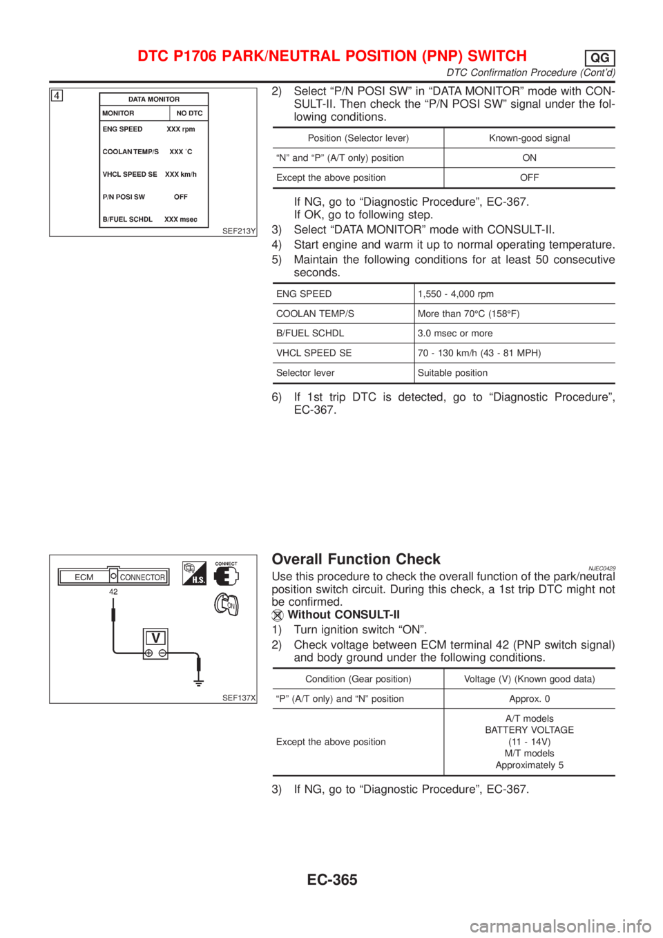
SEF213Y
2) Select ªP/N POSI SWº in ªDATA MONITORº mode with CON-
SULT-II. Then check the ªP/N POSI SWº signal under the fol-
lowing conditions.
Position (Selector lever) Known-good signal
ªNº and ªPº (A/T only) position ON
Except the above position OFF
If NG, go to ªDiagnostic Procedureº, EC-367.
If OK, go to following step.
3) Select ªDATA MONITORº mode with CONSULT-II.
4) Start engine and warm it up to normal operating temperature.
5) Maintain the following conditions for at least 50 consecutive
seconds.
ENG SPEED 1,550 - 4,000 rpm
COOLAN TEMP/S More than 70ÉC (158ÉF)
B/FUEL SCHDL 3.0 msec or more
VHCL SPEED SE 70 - 130 km/h (43 - 81 MPH)
Selector lever Suitable position
6) If 1st trip DTC is detected, go to ªDiagnostic Procedureº,
EC-367.
SEF137X
Overall Function CheckNJEC0429Use this procedure to check the overall function of the park/neutral
position switch circuit. During this check, a 1st trip DTC might not
be confirmed.
Without CONSULT-II
1) Turn ignition switch ªONº.
2) Check voltage between ECM terminal 42 (PNP switch signal)
and body ground under the following conditions.
Condition (Gear position) Voltage (V) (Known good data)
ªPº (A/T only) and ªNº position Approx. 0
Except the above positionA/T models
BATTERY VOLTAGE
(11 - 14V)
M/T models
Approximately 5
3) If NG, go to ªDiagnostic Procedureº, EC-367.
DTC P1706 PARK/NEUTRAL POSITION (PNP) SWITCHQG
DTC Confirmation Procedure (Cont'd)
EC-365
Page 663 of 2493
Diagnostic ProcedureNJEC0431
1 CHECK GROUND CIRCUIT
1. Turn ignition switch ªOFFº.
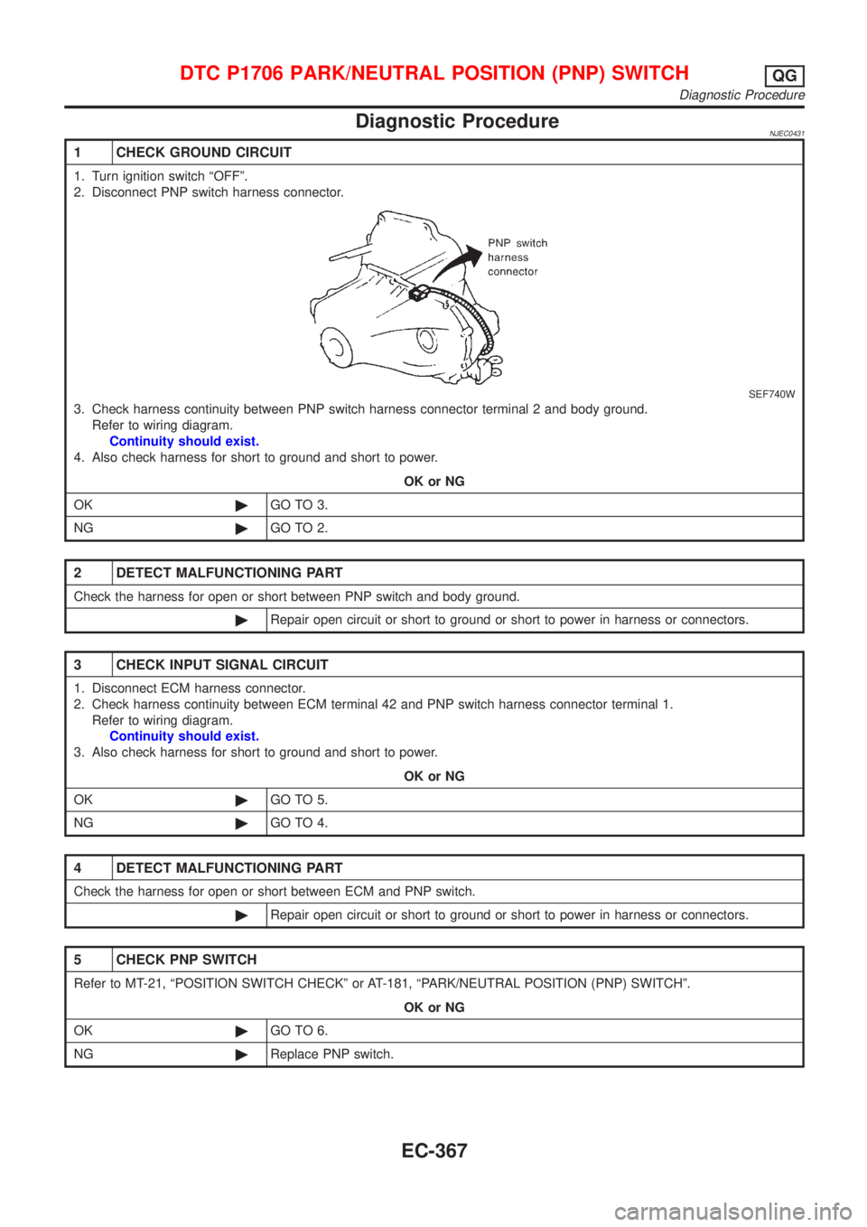
2. Disconnect PNP switch harness connector.
SEF740W
3. Check harness continuity between PNP switch harness connector terminal 2 and body ground.
Refer to wiring diagram.
Continuity should exist.
4. Also check harness for short to ground and short to power.
OK or NG
OK©GO TO 3.
NG©GO TO 2.
2 DETECT MALFUNCTIONING PART
Check the harness for open or short between PNP switch and body ground.
©Repair open circuit or short to ground or short to power in harness or connectors.
3 CHECK INPUT SIGNAL CIRCUIT
1. Disconnect ECM harness connector.
2. Check harness continuity between ECM terminal 42 and PNP switch harness connector terminal 1.
Refer to wiring diagram.
Continuity should exist.
3. Also check harness for short to ground and short to power.
OK or NG
OK©GO TO 5.
NG©GO TO 4.
4 DETECT MALFUNCTIONING PART
Check the harness for open or short between ECM and PNP switch.
©Repair open circuit or short to ground or short to power in harness or connectors.
5 CHECK PNP SWITCH
Refer to MT-21, ªPOSITION SWITCH CHECKº or AT-181, ªPARK/NEUTRAL POSITION (PNP) SWITCHº.
OK or NG
OK©GO TO 6.
NG©Replace PNP switch.
DTC P1706 PARK/NEUTRAL POSITION (PNP) SWITCHQG
Diagnostic Procedure
EC-367
Page 667 of 2493
Diagnostic ProcedureNJEC1739
1 CHECK OVERALL FUNCTION
1. Turn ignition switch ªONº.
2. Check voltage between ECM terminal 64 and ground with CONSULT-II or tester.
SEF004YA
OK or NG
OK©INSPECTION END
NG©GO TO 2.
2 CHECK POWER SUPPLY (Models with intake air temperature sensor in mass air flow sensor)
1. Turn ignition switch ªOFFº.
2. Disconnect mass air flow sensor harness connector.
JEF105Y
3. Turn ignition switch ªONº.
4. Check voltage between terminal 1 and ground with CONSULT-II or tester.
SEC503C
OK or NG
OK©GO TO 4.
NG©GO TO 3.
INTAKE AIR TEMPERATURE SENSORQG
Diagnostic Procedure
EC-371
Page 668 of 2493
3 DETECT MALFUNCTIONING PART
Check harness for open or short between ECM and intake air temperature sensor.
©Repair harness or connectors.
4 CHECK GROUND CIRCUIT
1. Turn ignition switch ªOFFº.
2. Check harness continuity between mass air flow sensor harness connector terminal 3 and engine ground.
Refer to wiring diagram.
Continuity should exist.
3. Also check harness for short to ground and short to power.
OK or NG
OK©GO TO 6.
NG©GO TO 5.
5 DETECT MALFUNCTIONING PART
Check harness for open or short between ECM and intake air temperature sensor.
©Repair open circuit or short to ground or short to power in harness or connectors.
6 CHECK INTAKE AIR TEMPERATURE SENSOR
Refer to ªComponent Inspectionº, EC-372.
OK or NG
OK©GO TO 7.
NG©Replace intake air temperature sensor.
7 CHECK INTERMITTENT INCIDENT
Perform ªTROUBLE DIAGNOSIS FOR INTERMITTENT INCIDENTº, EC-144.
©INSPECTION END
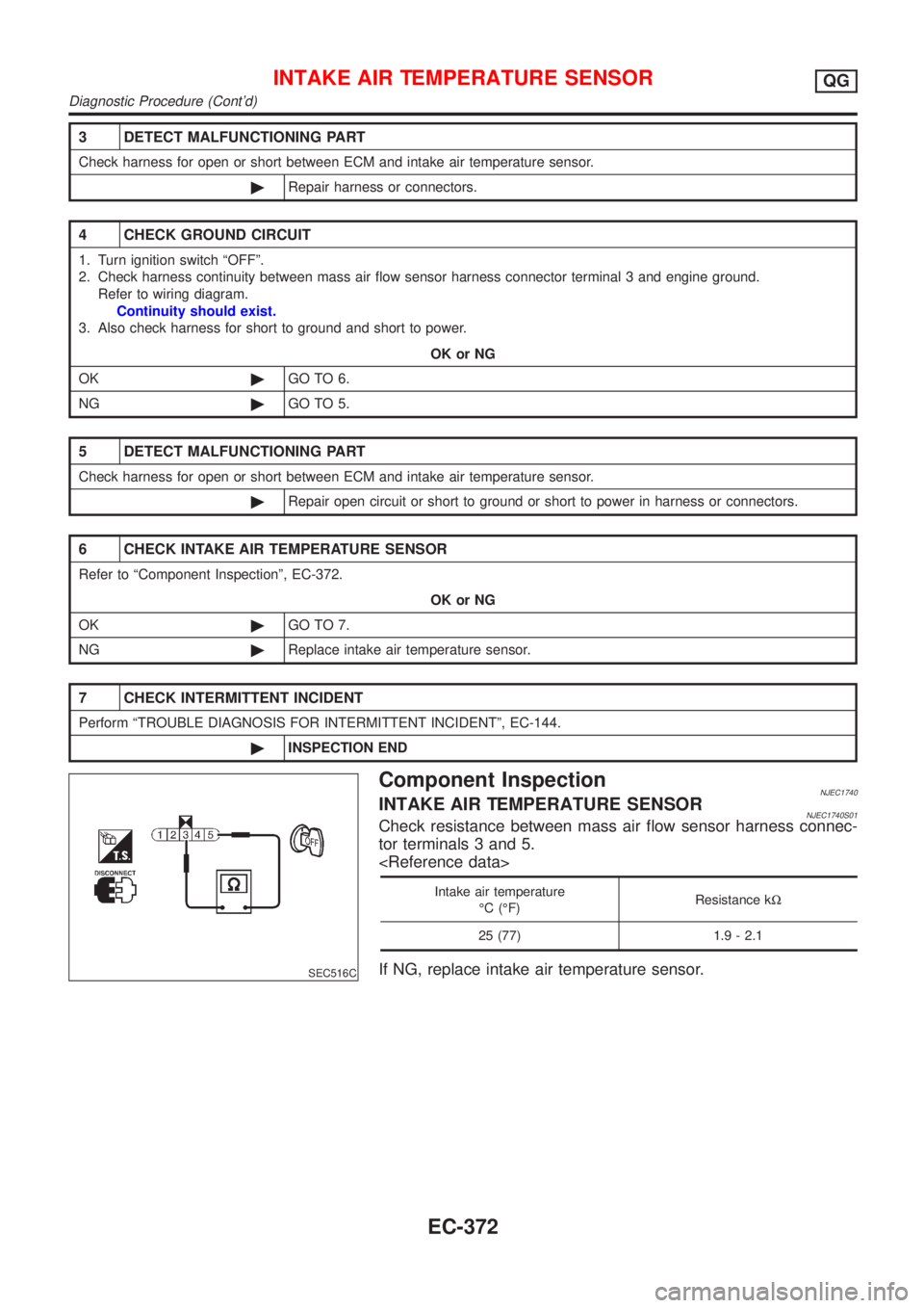
SEC516C
Component InspectionNJEC1740INTAKE AIR TEMPERATURE SENSORNJEC1740S01Check resistance between mass air flow sensor harness connec-
tor terminals 3 and 5.
Intake air temperature
ÉC (ÉF)Resistance kW
25 (77) 1.9 - 2.1
If NG, replace intake air temperature sensor.
INTAKE AIR TEMPERATURE SENSORQG
Diagnostic Procedure (Cont'd)
EC-372
Page 672 of 2493
4 RETIGHTEN GROUND SCREWS
1. Turn ignition switch ªOFFº.
2. Loosen and retighten engine ground screws.
JEF104Y
3. Disconnect heated oxygen sensor 1 (front) harness connector.
SEF012XA
©GO TO 5.
5 RETIGHTEN HEATED OXYGEN SENSOR 1 (FRONT)
Loosen and retighten corresponding heated oxygen sensor 1 (front).
Tightening torque:
40 - 50 N´m (4.1 - 5.1 kg-m, 30 - 37 ft-lb)
©GO TO 6.
6 CHECK INPUT SIGNAL CIRCUIT
1. Disconnect ECM harness connector.
2. Check harness continuity between ECM terminal 62 and heated oxygen sensor 1 (front) harness connector terminal 2.
Refer to wiring diagram.
Continuity should exist.
3. Check harness continuity between ECM terminal 62 (or terminal 2) and ground.
Continuity should not exist.
4. Also check harness for short to power.
OK or NG
OK©GO TO 7.
NG©Repair open circuit or short to ground or short to power in harness or connectors.
HEATED OXYGEN SENSOR 1 (FRONT)QG
Diagnostic Procedure (Cont'd)
EC-376
Page 677 of 2493
Diagnostic ProcedureNJEC1229
1 CHECK OVERALL FUNCTION
1. Turn ignition switch ªONº.
2. Set the tester probe between ECM terminals 4 [HO2S1 Heater (front) signal] and ground.
3. Start engine and let it idle.
4. Check the voltage under the following conditions.
SEF239Z
OK or NG
OK©INSPECTION END
NG©GO TO 2.
2 CHECK POWER SUPPLY
1. Turn ignition switch ªOFFº.
2. Disconnect heated oxygen sensor 1 (front) harness connector.
SEF012XA
3. Turn ignition switch ªONº.
4. Check voltage between terminal 1 and ground with CONSULT-II or tester.
SEF934X
OK or NG
OK©GO TO 4.
NG©GO TO 3.
HEATED OXYGEN SENSOR 1 HEATER (FRONT)QG
Diagnostic Procedure
EC-381
Page 678 of 2493
3 DETECT MALFUNCTIONING PART
Check the following.
+Harness connectors F113, M169
+10A fuse
+Harness for open or short between heated oxygen sensor 1 (front) and fuse
©Repair harness or connectors.
4 CHECK GROUND CIRCUIT
1. Turn ignition switch ªOFFº.
2. Disconnect ECM harness connector.
3. Check harness continuity between heated oxygen sensor 1 (front) harness connector terminal 3 and ECM terminal 4.
Refer to wiring diagram.
Continuity should exist.
4. Also check harness for short to ground and short to power.
OK or NG
OK©GO TO 5.
NG©Repair open circuit or short to ground or short to power in harness or connectors.
5 CHECK HEATED OXYGEN SENSOR 1 HEATER (FRONT)
Refer to ªComponent Inspectionº, EC-382.
OK or NG
OK©GO TO 6.
NG©Replace heated oxygen sensor 1 (front).
6 CHECK INTERMITTENT INCIDENT
Perform ªTROUBLE DIAGNOSIS FOR INTERMITTENT INCIDENTº, EC-144.
©INSPECTION END
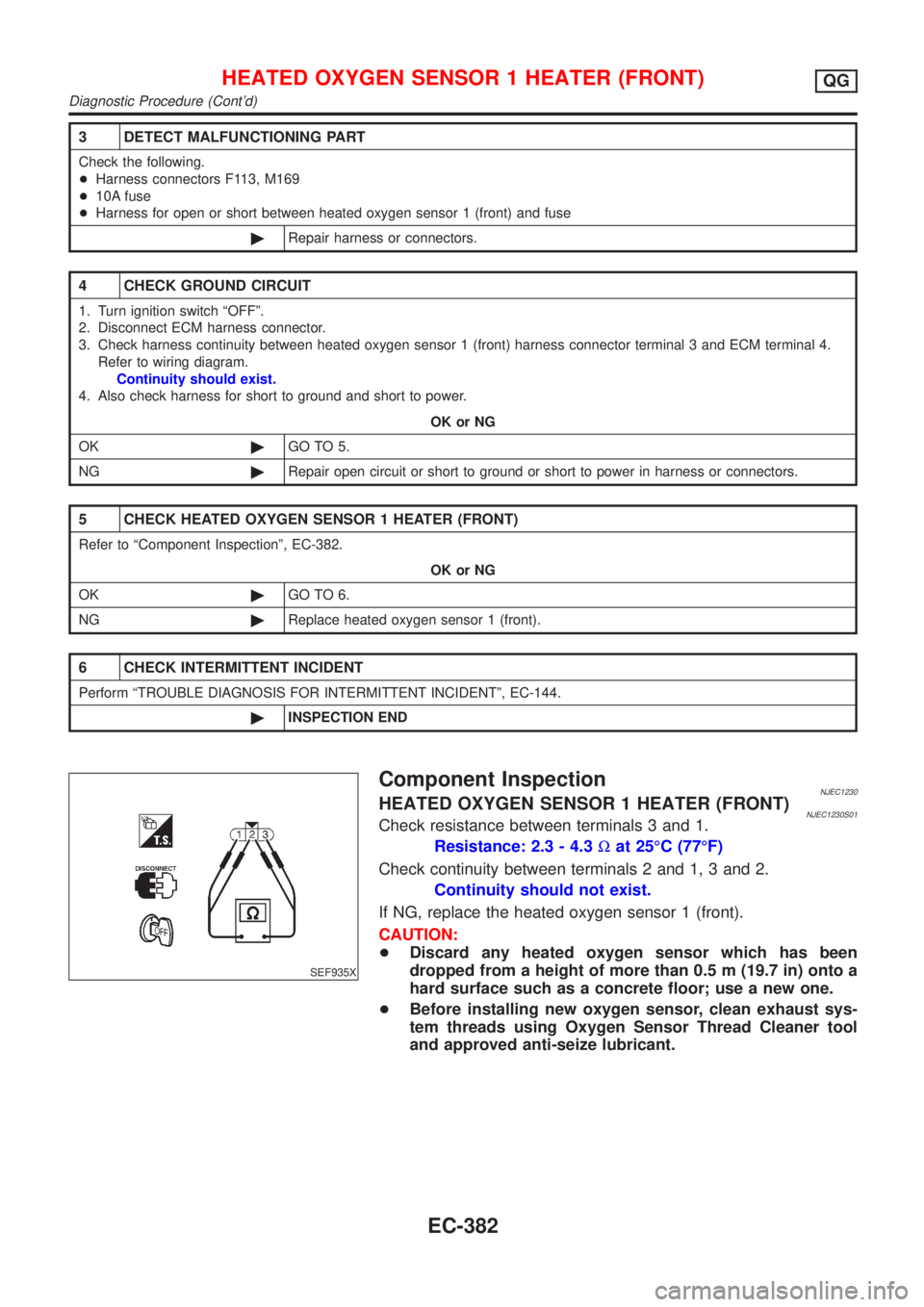
SEF935X
Component InspectionNJEC1230HEATED OXYGEN SENSOR 1 HEATER (FRONT)NJEC1230S01Check resistance between terminals 3 and 1.
Resistance: 2.3 - 4.3Wat 25ÉC (77ÉF)
Check continuity between terminals 2 and 1, 3 and 2.
Continuity should not exist.
If NG, replace the heated oxygen sensor 1 (front).
CAUTION:
+Discard any heated oxygen sensor which has been
dropped from a height of more than 0.5 m (19.7 in) onto a
hard surface such as a concrete floor; use a new one.
+Before installing new oxygen sensor, clean exhaust sys-
tem threads using Oxygen Sensor Thread Cleaner tool
and approved anti-seize lubricant.
HEATED OXYGEN SENSOR 1 HEATER (FRONT)QG
Diagnostic Procedure (Cont'd)
EC-382