2001 NISSAN ALMERA N16 wheel bolt torque
[x] Cancel search: wheel bolt torquePage 1693 of 2493

SRA695A
SSU038
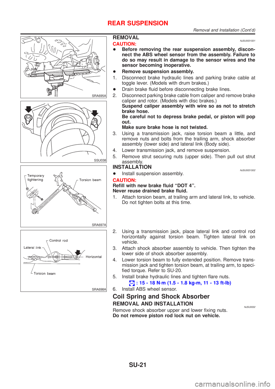
REMOVALNJSU0031S01CAUTION:
+Before removing the rear suspension assembly, discon-
nect the ABS wheel sensor from the assembly. Failure to
do so may result in damage to the sensor wires and the
sensor becoming inoperative.
+Remove suspension assembly.
1. Disconnect brake hydraulic lines and parking brake cable at
toggle lever. (Models with drum brakes.)
+Drain brake fluid before disconnecting brake lines.
2. Disconnect parking brake cable from caliper and remove brake
caliper and rotor. (Models with disc brakes.)
Suspend caliper assembly with wire so as not to stretch
brake hose.
Be careful not to depress brake pedal, or piston will pop
out.
Make sure brake hose is not twisted.
3. Using a transmission jack, raise torsion beam a little, and
remove nuts and bolts from the trailing arm, shock absorber
assembly (lower side) and lateral link (Body side).
4. Lower transmission jack, and remove suspension.
5. Remove strut securing nuts (upper side). Then pull out strut
assembly.
SRA697A
INSTALLATIONNJSU0031S02+Install suspension assembly.
CAUTION:
Refill with new brake fluid ªDOT 4º.
Never reuse drained brake fluid.
1. Attach torsion beam, at trailing arm and lateral link, to vehicle.
Do not tighten bolts at this time.
SRA698A
2. Using a transmission jack, place lateral link and control rod
horizontally against torsion beam. Tighten lateral link on
vehicle.
3. Attach shock absorber assembly to vehicle. Then tighten the
lower side of shock absorber assembly.
4. Lower torsion beam to fully extended position. Remove trans-
mission jack and tighten torsion beam, at trailing arm, to speci-
fied torque. Refer to SU-20.
5. Install brake hydraulic lines and tighten flare nuts.
: 15 - 18 N´m (1.5 - 1.8 kg-m, 11 - 13 ft-lb)
6. Install ABS wheel sensor.
Coil Spring and Shock Absorber
REMOVAL AND INSTALLATIONNJSU0032Remove shock absorber upper and lower fixing nuts.
Do not remove piston rod lock nut on vehicle.
REAR SUSPENSION
Removal and Installation (Cont'd)
SU-21
Page 1744 of 2493

SBR219C
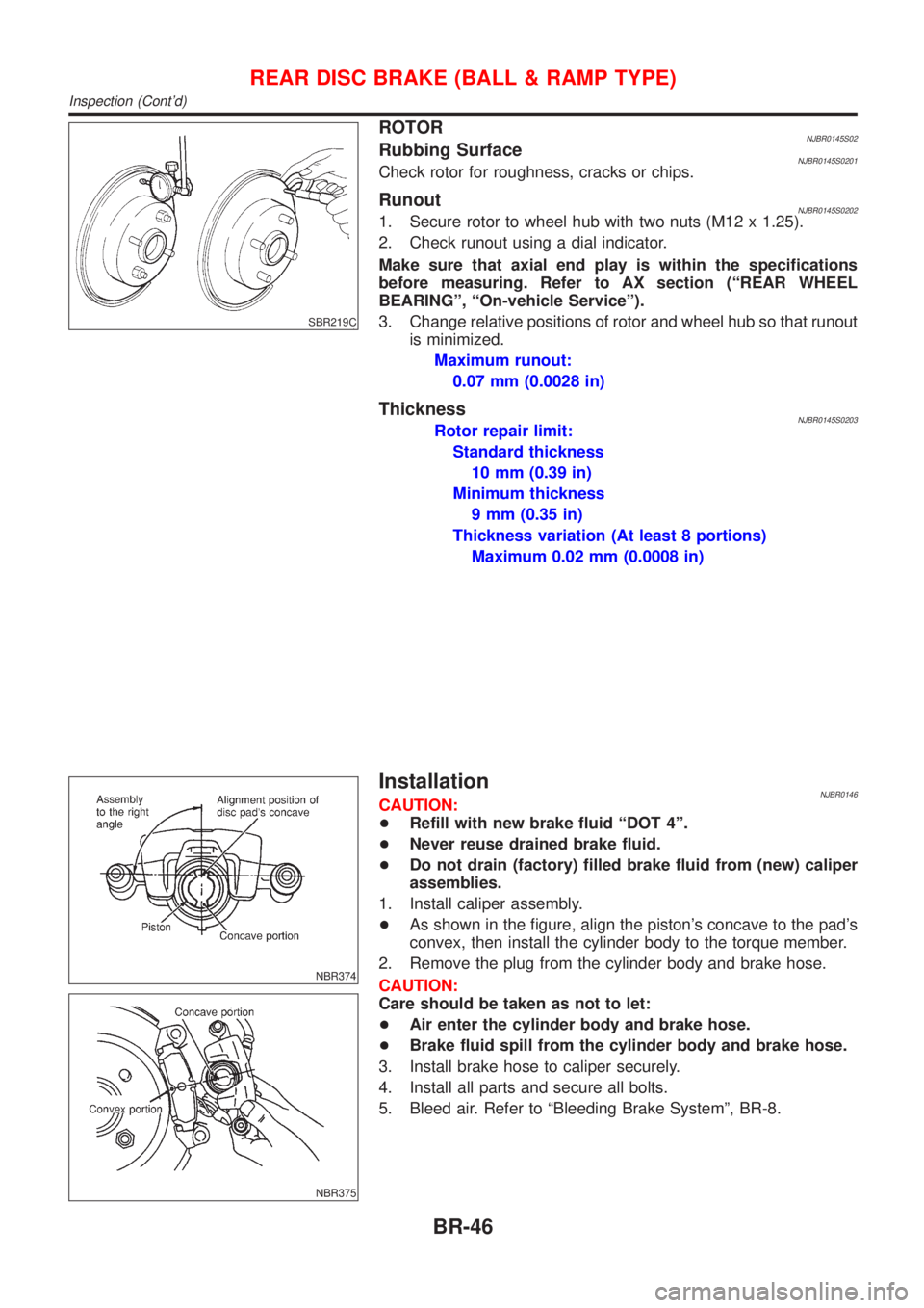
ROTORNJBR0145S02Rubbing SurfaceNJBR0145S0201Check rotor for roughness, cracks or chips.
RunoutNJBR0145S02021. Secure rotor to wheel hub with two nuts (M12 x 1.25).
2. Check runout using a dial indicator.
Make sure that axial end play is within the specifications
before measuring. Refer to AX section (ªREAR WHEEL
BEARINGº, ªOn-vehicle Serviceº).
3. Change relative positions of rotor and wheel hub so that runout
is minimized.
Maximum runout:
0.07 mm (0.0028 in)
ThicknessNJBR0145S0203Rotor repair limit:
Standard thickness
10 mm (0.39 in)
Minimum thickness
9 mm (0.35 in)
Thickness variation (At least 8 portions)
Maximum 0.02 mm (0.0008 in)
NBR374
NBR375
InstallationNJBR0146CAUTION:
+Refill with new brake fluid ªDOT 4º.
+Never reuse drained brake fluid.
+Do not drain (factory) filled brake fluid from (new) caliper
assemblies.
1. Install caliper assembly.
+As shown in the figure, align the piston's concave to the pad's
convex, then install the cylinder body to the torque member.
2. Remove the plug from the cylinder body and brake hose.
CAUTION:
Care should be taken as not to let:
+Air enter the cylinder body and brake hose.
+Brake fluid spill from the cylinder body and brake hose.
3. Install brake hose to caliper securely.
4. Install all parts and secure all bolts.
5. Bleed air. Refer to ªBleeding Brake Systemº, BR-8.
REAR DISC BRAKE (BALL & RAMP TYPE)
Inspection (Cont'd)
BR-46
Page 1807 of 2493

SST879C
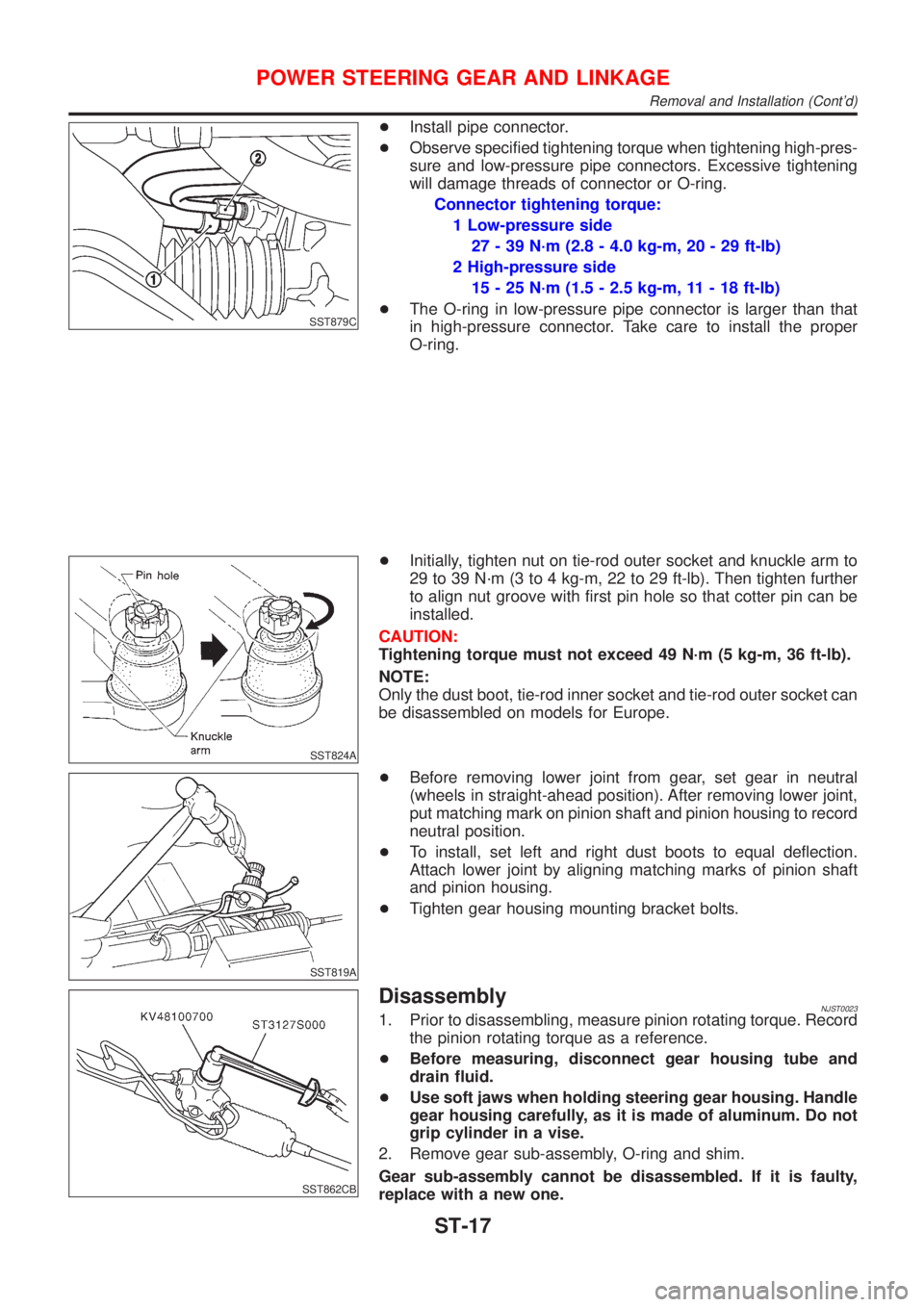
+Install pipe connector.
+Observe specified tightening torque when tightening high-pres-
sure and low-pressure pipe connectors. Excessive tightening
will damage threads of connector or O-ring.
Connector tightening torque:
1 Low-pressure side
27 - 39 N´m (2.8 - 4.0 kg-m, 20 - 29 ft-lb)
2 High-pressure side
15 - 25 N´m (1.5 - 2.5 kg-m, 11 - 18 ft-lb)
+The O-ring in low-pressure pipe connector is larger than that
in high-pressure connector. Take care to install the proper
O-ring.
SST824A
+Initially, tighten nut on tie-rod outer socket and knuckle arm to
29 to 39 N´m (3 to 4 kg-m, 22 to 29 ft-lb). Then tighten further
to align nut groove with first pin hole so that cotter pin can be
installed.
CAUTION:
Tightening torque must not exceed 49 N´m (5 kg-m, 36 ft-lb).
NOTE:
Only the dust boot, tie-rod inner socket and tie-rod outer socket can
be disassembled on models for Europe.
SST819A
+Before removing lower joint from gear, set gear in neutral
(wheels in straight-ahead position). After removing lower joint,
put matching mark on pinion shaft and pinion housing to record
neutral position.
+To install, set left and right dust boots to equal deflection.
Attach lower joint by aligning matching marks of pinion shaft
and pinion housing.
+Tighten gear housing mounting bracket bolts.
SST862CB
DisassemblyNJST00231. Prior to disassembling, measure pinion rotating torque. Record
the pinion rotating torque as a reference.
+Before measuring, disconnect gear housing tube and
drain fluid.
+Use soft jaws when holding steering gear housing. Handle
gear housing carefully, as it is made of aluminum. Do not
grip cylinder in a vise.
2. Remove gear sub-assembly, O-ring and shim.
Gear sub-assembly cannot be disassembled. If it is faulty,
replace with a new one.
POWER STEERING GEAR AND LINKAGE
Removal and Installation (Cont'd)
ST-17
Page 2487 of 2493

Shock absorber (rear) ............................... SU-21
Side air bag ............................................... RS-33
Side trim .................................................... BT-31
Spare tire size ............................................ GI-43
Speedometer ............................................. EL-89
Spiral cable ............................................... RS-29
Spot lamp .................................................. EL-87
Spring (Wheelarch) height .......................... SU-6
Stabilizer bar (front) ................................... SU-11
Stall test (A/T) ............................................ AT-78
Standardized relay ....................................... EL-7
Start signal ...................................... EC-460, 693
Starter ....................................................... SC-16
Starting system ......................................... SC-13
Steering linkage ......................................... ST-15
Steering switch .......................................... EL-39
Steering wheel and column ....................... ST-10
Steering wheel play ..................................... ST-6
Steering wheel turning force ....................... ST-8
Stop lamp .................................................. EL-56
Striking rod (M/T) .......................... MT-32, 56, 94
Strut (front) .................................................. SU-9
Strut (rear) ................................................. SU-20
Sub-gear (M/T) ................................... MT-31, 55
Sunroof, electric ....................................... EL-165
Sunroof ...................................................... BT-60
Super lock ................................................ EL-196
Supplemental Restraint System ............... RS-20
Supplemental restraint system - Wiring
diagram .................................................. RS-46
Symbols and abbreviations ........................ GI-11
Symptom matrix chart ..................... EC-124, 541
Synchronizer (M/T) ....................... MT-31, 55, 93
System readiness test (SRT) code ........... EC-60
T
TCM circuit diagram ................................... AT-17
TCM inspection table ............................... AT-117
TP/SW - Wiring diagram ................. EC-323, 427
TPS - Wiring diagram ............................. EC-171
TURN - Wiring diagram ............................. EL-67
Tachometer ................................................ EL-89
Tail lamp .................................................... EL-53
Thermostat .......................................... LC-15, 40
Three way catalyst precautions ................... GI-6
Three way catalyst .................................. EC-299
Throttle position sensor (TPS) ................ EC-168
Throttle position sensor adjustment .......... EC-98
Throttle position switch ........... AT-139, 264, 333,
EC-321, 426
Throwout bearing - See Clutch release
bearing ............................................. CL-17, 20
Tie-rod ball joints ....................................... ST-19
Tie-rod ........................................................ ST-15
Tightening torque of standard bolts ........... GI-49
Timing chain ....................................... EM-22, 93
Tire size ...................................................... GI-43
Torque converter installation .................... AT-347Tow truck towing ........................................ GI-47
Transmission case (M/T) .............. MT-30, 54, 92
Tread-FR&RR (Dimensions) ...................... GI-43
Trim ............................................................ BT-31
Trouble diagnoses ...................................... GI-31
Trunk lid finisher ........................................ BT-45
Trunk lid opener - See Trunk lid ................ BT-10
Trunk lid trim .............................................. BT-45
Trunk lid ..................................................... BT-10
Trunk room lamp ....................................... EL-87
Trunk room trim ......................................... BT-45
Turn signal lamp ........................................ EL-65
Two trip detection logic ............................. EC-57
Two-pole lift ................................................ GI-46
U
Under body ................................................ BT-77
V
VSS - Wiring diagram ..................... EC-311, 593
Vacuum hose (brake system) ................... BR-22
Vacuum hose drawing (Engine control) .... EC-27
Vacuum pump ........................................... BR-23
Valve clearance ................................ EM-42, 132
Valve guide ....................................... EM-38, 123
Valve lifter ................................................. EM-41
Valve seat ......................................... EM-40, 125
Valve spring ...................................... EM-41, 127
Vehicle speed sensor (VSS) ........... EC-309, 593
Viscosity number (SAE) ............................ MA-21
Viscous coupling (FF M/T) ........................ MT-93
W
WARN - Wiring diagram .......................... EL-108
WIP/R - Wiring diagram .......................... EL-129
WIPER - Wiring diagram ......................... EL-125
Warning chime ......................................... EL-113
Warning lamps ......................................... EL-107
Washer, front ........................................... EL-123
Water pump ......................................... LC-14, 38
Water temperature gauge .......................... EL-89
Weatherstrip - See Exterior ....................... BT-47
Wheel alignment (rear) ............................. SU-18
Wheel bearing (front) .................................. AX-3
Wheel bearing (rear) ................................. AX-23
Wheel hub (front) ........................................ AX-5
Wheel hub (rear) ....................................... AX-24
Wheel sensors (ABS) ............................... BR-88
Wheelarch height ........................................ SU-6
Wheelbase (Dimensions) ........................... GI-43
Wide open & closed throttle position
switch ................................................... EC-168
Width (Dimensions) .................................... GI-43
Window, rear .............................................. BT-68
ALPHABETICAL INDEX
IDX-7