2001 NISSAN ALMERA N16 OBD port
[x] Cancel search: OBD portPage 1247 of 2493
DTC work support item Description Check items (Possible cause)
4TH GR FNCTN P0734Following items for ªA/T 4th gear function (P0734)º can be con-
firmed.
+Self-diagnosis status (whether the diagnosis is being con-
ducted or not)
+Self-diagnosis result (OK or NG)+Shift solenoid valve A
+Shift solenoid valve B
+Overrun clutch solenoid valve
+Line pressure solenoid valve
+Each clutch
+Hydraulic control circuit
Diagnostic Procedure Without CONSULT-IINJAT0352EURO-OBD SELF-DIAGNOSTIC PROCEDURE (WITH
GST)
NJAT0352S04Refer to EC-92, section ªGeneric Scan Tool (GST)º.
EURO-OBD SELF-DIAGNOSTIC PROCEDURE (NO
TOOLS)
NJAT0352S05Refer to EC-72, ªMalfunction Indicator (MI)º.
SAT491J
SAT851JA
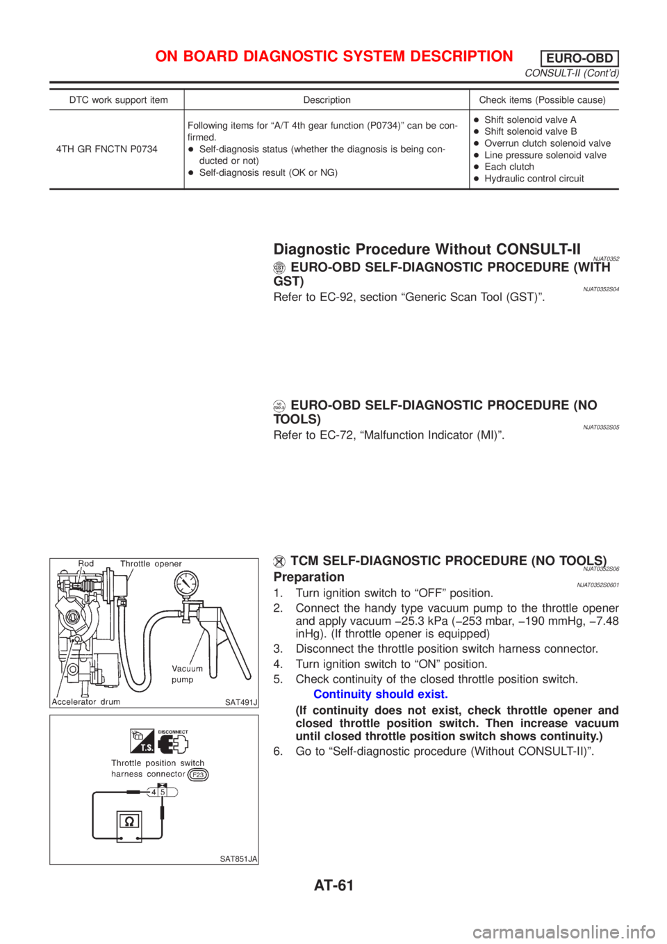
TCM SELF-DIAGNOSTIC PROCEDURE (NO TOOLS)NJAT0352S06PreparationNJAT0352S06011. Turn ignition switch to ªOFFº position.
2. Connect the handy type vacuum pump to the throttle opener
and apply vacuum þ25.3 kPa (þ253 mbar, þ190 mmHg, þ7.48
inHg). (If throttle opener is equipped)
3. Disconnect the throttle position switch harness connector.
4. Turn ignition switch to ªONº position.
5. Check continuity of the closed throttle position switch.
Continuity should exist.
(If continuity does not exist, check throttle opener and
closed throttle position switch. Then increase vacuum
until closed throttle position switch shows continuity.)
6. Go to ªSelf-diagnostic procedure (Without CONSULT-II)º.
ON BOARD DIAGNOSTIC SYSTEM DESCRIPTIONEURO-OBD
CONSULT-II (Cont'd)
AT-61
Page 1257 of 2493
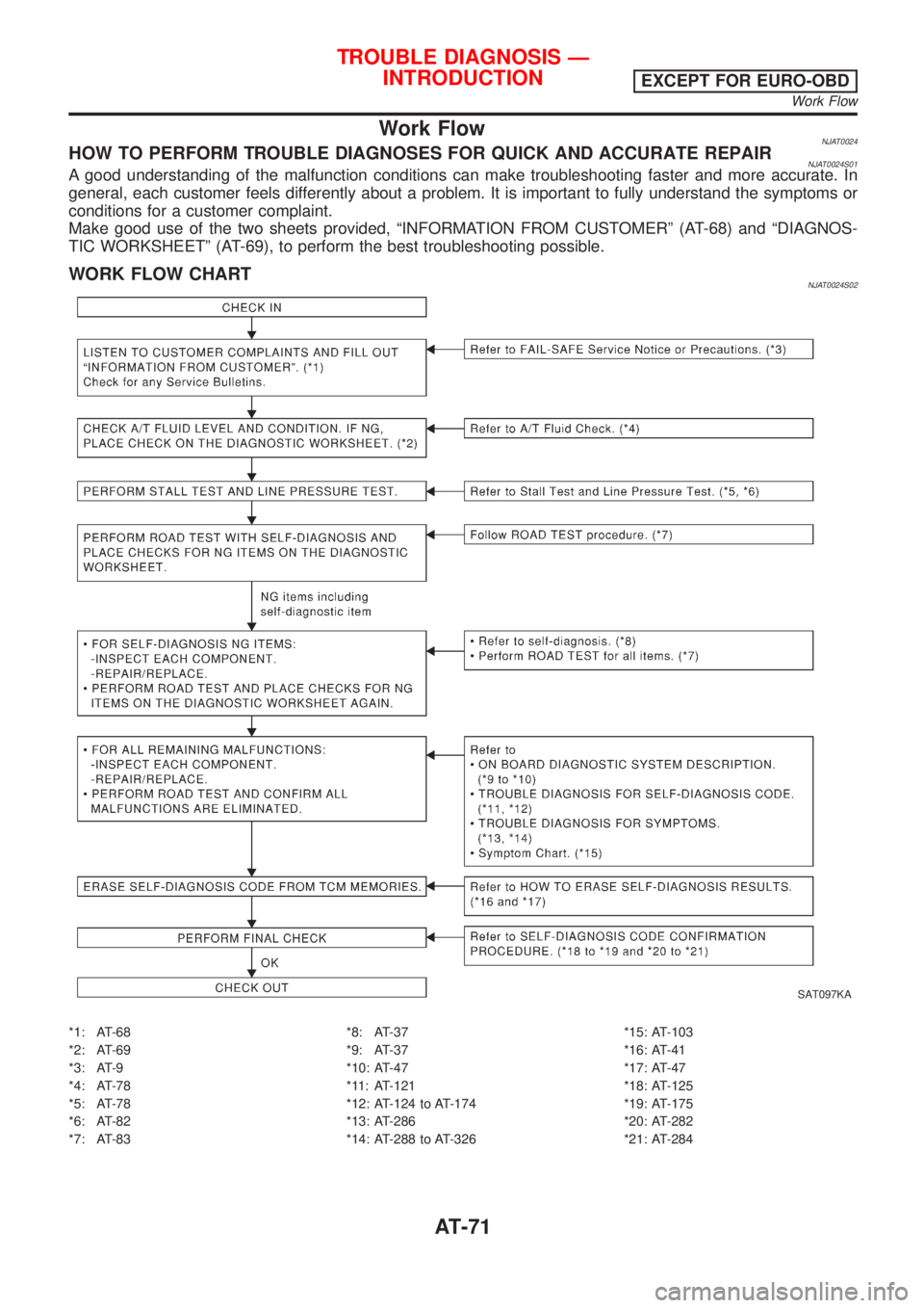
Work FlowNJAT0024HOW TO PERFORM TROUBLE DIAGNOSES FOR QUICK AND ACCURATE REPAIRNJAT0024S01A good understanding of the malfunction conditions can make troubleshooting faster and more accurate. In
general, each customer feels differently about a problem. It is important to fully understand the symptoms or
conditions for a customer complaint.
Make good use of the two sheets provided, ªINFORMATION FROM CUSTOMERº (AT-68) and ªDIAGNOS-
TIC WORKSHEETº (AT-69), to perform the best troubleshooting possible.
WORK FLOW CHARTNJAT0024S02
SAT097KA
*1: AT-68
*2: AT-69
*3: AT-9
*4: AT-78
*5: AT-78
*6: AT-82
*7: AT-83*8: AT-37
*9: AT-37
*10: AT-47
*11: AT-121
*12: AT-124 to AT-174
*13: AT-286
*14: AT-288 to AT-326*15: AT-103
*16: AT-41
*17: AT-47
*18: AT-125
*19: AT-175
*20: AT-282
*21: AT-284
TROUBLE DIAGNOSIS Ð
INTRODUCTION
EXCEPT FOR EURO-OBD
Work Flow
AT-71
Page 1262 of 2493

Work FlowNJAT0258HOW TO PERFORM TROUBLE DIAGNOSES FOR QUICK AND ACCURATE REPAIRNJAT0258S01A good understanding of the malfunction conditions can make troubleshooting faster and more accurate. In
general, each customer feels differently about a problem. It is important to fully understand the symptoms or
conditions for a customer complaint.
Make good use of the two sheets provided, ªINFORMATION FROM CUSTOMERº (AT-73) and ªDIAGNOS-
TIC WORKSHEETº (AT-74), to perform the best troubleshooting possible.
TROUBLE DIAGNOSIS Ð INTRODUCTIONEURO-OBD
Work Flow
AT-76
Page 1389 of 2493
Diagnostic trouble code Malfunction is detected when ... Check items (Possible cause)
: A/T 1ST GR FNCTN
A/T cannot be shifted to the 1st gear
position even if electrical circuit is good.+Shift solenoid valve A
+Shift solenoid valve B
+Each clutch
+Hydraulic control circuit
: P0731
SAT014K
SAT971J
SAT021J
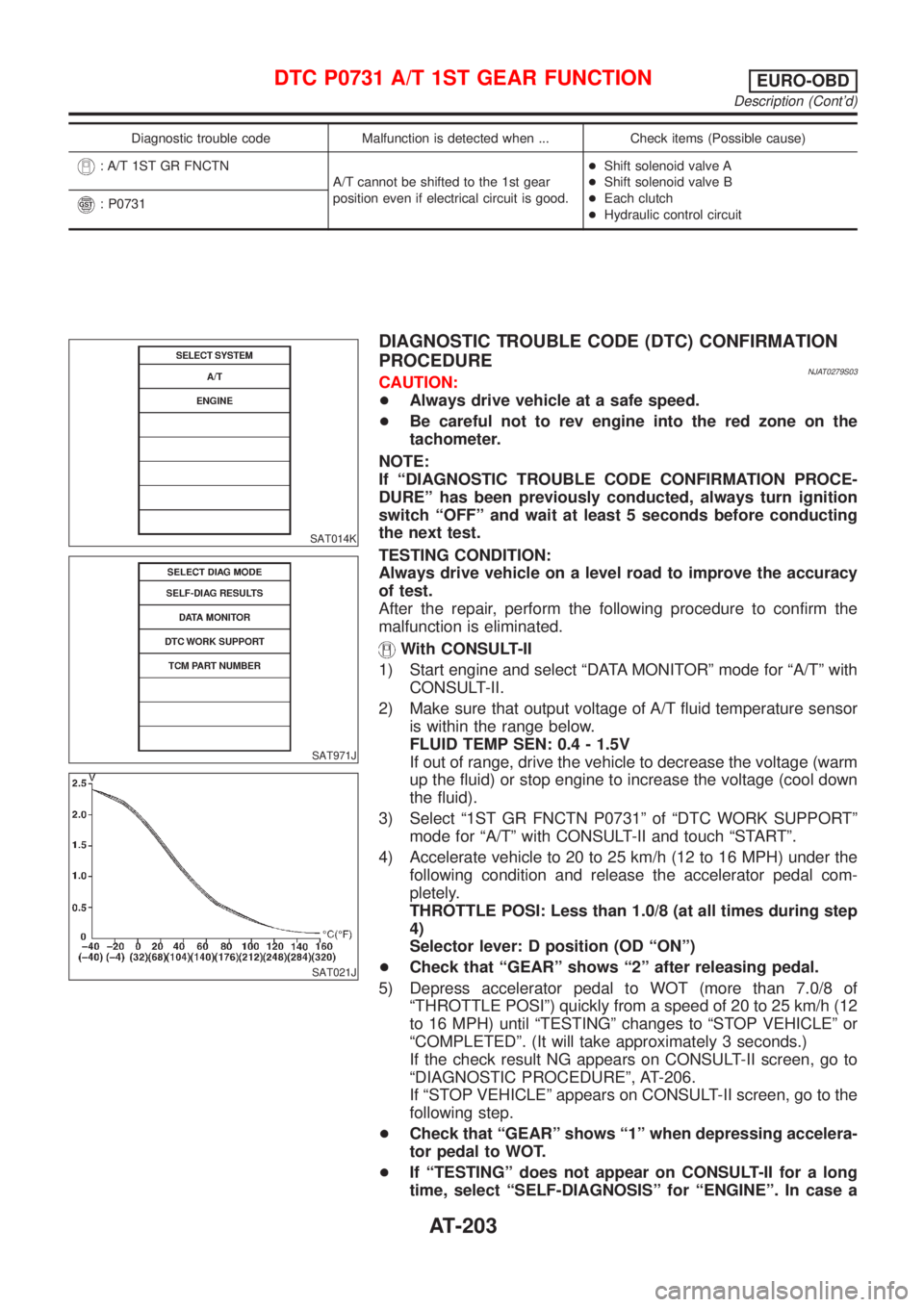
DIAGNOSTIC TROUBLE CODE (DTC) CONFIRMATION
PROCEDURE
NJAT0279S03CAUTION:
+Always drive vehicle at a safe speed.
+Be careful not to rev engine into the red zone on the
tachometer.
NOTE:
If ªDIAGNOSTIC TROUBLE CODE CONFIRMATION PROCE-
DUREº has been previously conducted, always turn ignition
switch ªOFFº and wait at least 5 seconds before conducting
the next test.
TESTING CONDITION:
Always drive vehicle on a level road to improve the accuracy
of test.
After the repair, perform the following procedure to confirm the
malfunction is eliminated.
With CONSULT-II
1) Start engine and select ªDATA MONITORº mode for ªA/Tº with
CONSULT-II.
2) Make sure that output voltage of A/T fluid temperature sensor
is within the range below.
FLUID TEMP SEN: 0.4 - 1.5V
If out of range, drive the vehicle to decrease the voltage (warm
up the fluid) or stop engine to increase the voltage (cool down
the fluid).
3) Select ª1ST GR FNCTN P0731º of ªDTC WORK SUPPORTº
mode for ªA/Tº with CONSULT-II and touch ªSTARTº.
4) Accelerate vehicle to 20 to 25 km/h (12 to 16 MPH) under the
following condition and release the accelerator pedal com-
pletely.
THROTTLE POSI: Less than 1.0/8 (at all times during step
4)
Selector lever: D position (OD ªONº)
+Check that ªGEARº shows ª2º after releasing pedal.
5) Depress accelerator pedal to WOT (more than 7.0/8 of
ªTHROTTLE POSIº) quickly from a speed of 20 to 25 km/h (12
to 16 MPH) until ªTESTINGº changes to ªSTOP VEHICLEº or
ªCOMPLETEDº. (It will take approximately 3 seconds.)
If the check result NG appears on CONSULT-II screen, go to
ªDIAGNOSTIC PROCEDUREº, AT-206.
If ªSTOP VEHICLEº appears on CONSULT-II screen, go to the
following step.
+Check that ªGEARº shows ª1º when depressing accelera-
tor pedal to WOT.
+If ªTESTINGº does not appear on CONSULT-II for a long
time, select ªSELF-DIAGNOSISº for ªENGINEº. In case a
DTC P0731 A/T 1ST GEAR FUNCTIONEURO-OBD
Description (Cont'd)
AT-203
Page 1396 of 2493
SAT014K
SAT971J
SAT021J
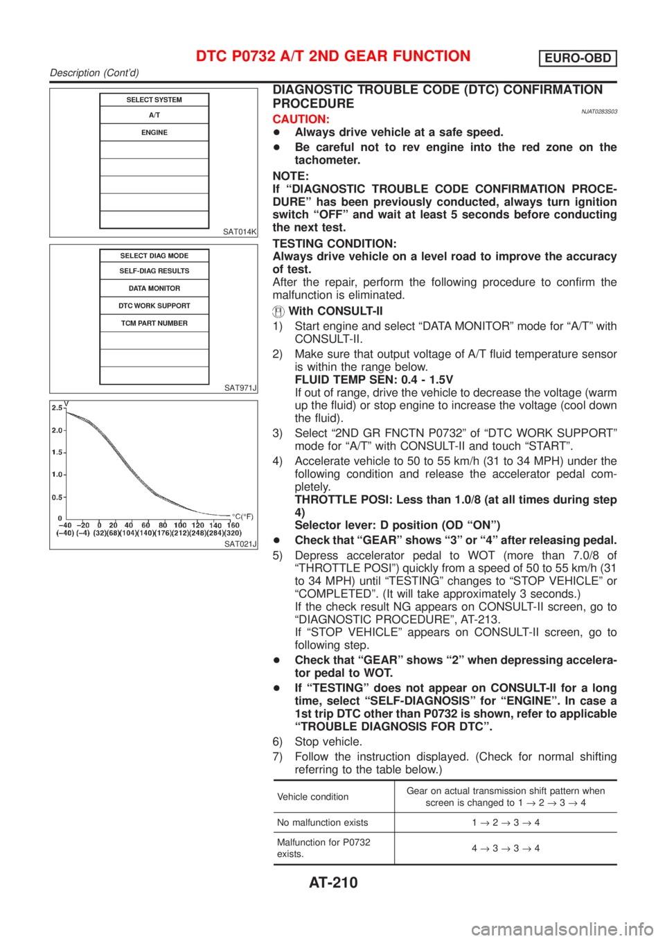
DIAGNOSTIC TROUBLE CODE (DTC) CONFIRMATION
PROCEDURE
NJAT0283S03CAUTION:
+Always drive vehicle at a safe speed.
+Be careful not to rev engine into the red zone on the
tachometer.
NOTE:
If ªDIAGNOSTIC TROUBLE CODE CONFIRMATION PROCE-
DUREº has been previously conducted, always turn ignition
switch ªOFFº and wait at least 5 seconds before conducting
the next test.
TESTING CONDITION:
Always drive vehicle on a level road to improve the accuracy
of test.
After the repair, perform the following procedure to confirm the
malfunction is eliminated.
With CONSULT-II
1) Start engine and select ªDATA MONITORº mode for ªA/Tº with
CONSULT-II.
2) Make sure that output voltage of A/T fluid temperature sensor
is within the range below.
FLUID TEMP SEN: 0.4 - 1.5V
If out of range, drive the vehicle to decrease the voltage (warm
up the fluid) or stop engine to increase the voltage (cool down
the fluid).
3) Select ª2ND GR FNCTN P0732º of ªDTC WORK SUPPORTº
mode for ªA/Tº with CONSULT-II and touch ªSTARTº.
4) Accelerate vehicle to 50 to 55 km/h (31 to 34 MPH) under the
following condition and release the accelerator pedal com-
pletely.
THROTTLE POSI: Less than 1.0/8 (at all times during step
4)
Selector lever: D position (OD ªONº)
+Check that ªGEARº shows ª3º or ª4º after releasing pedal.
5) Depress accelerator pedal to WOT (more than 7.0/8 of
ªTHROTTLE POSIº) quickly from a speed of 50 to 55 km/h (31
to 34 MPH) until ªTESTINGº changes to ªSTOP VEHICLEº or
ªCOMPLETEDº. (It will take approximately 3 seconds.)
If the check result NG appears on CONSULT-II screen, go to
ªDIAGNOSTIC PROCEDUREº, AT-213.
If ªSTOP VEHICLEº appears on CONSULT-II screen, go to
following step.
+Check that ªGEARº shows ª2º when depressing accelera-
tor pedal to WOT.
+If ªTESTINGº does not appear on CONSULT-II for a long
time, select ªSELF-DIAGNOSISº for ªENGINEº. In case a
1st trip DTC other than P0732 is shown, refer to applicable
ªTROUBLE DIAGNOSIS FOR DTCº.
6) Stop vehicle.
7) Follow the instruction displayed. (Check for normal shifting
referring to the table below.)
Vehicle conditionGear on actual transmission shift pattern when
screen is changed to 1®2®3®4
No malfunction exists 1®2®3®4
Malfunction for P0732
exists.4®3®3®4
DTC P0732 A/T 2ND GEAR FUNCTIONEURO-OBD
Description (Cont'd)
AT-210
Page 1402 of 2493
SAT014K
SAT971J
SAT021J
DIAGNOSTIC TROUBLE CODE (DTC) CONFIRMATION
PROCEDURE
NJAT0287S03CAUTION:
+Always drive vehicle at a safe speed.
+Be careful not to rev engine into the red zone on the
tachometer.
NOTE:
If ªDIAGNOSTIC TROUBLE CODE CONFIRMATION PROCE-
DUREº has been previously conducted, always turn ignition
switch ªOFFº and wait at least 5 seconds before conducting
the next test.
TESTING CONDITION:
Always drive vehicle on a level road to improve the accuracy
of test.
After the repair, perform the following procedure to confirm the
malfunction is eliminated.
With CONSULT-II
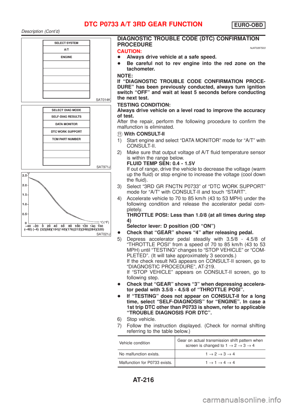
1) Start engine and select ªDATA MONITORº mode for ªA/Tº with
CONSULT-II.
2) Make sure that output voltage of A/T fluid temperature sensor
is within the range below.
FLUID TEMP SEN: 0.4 - 1.5V
If out of range, drive the vehicle to decrease the voltage (warm
up the fluid) or stop engine to increase the voltage (cool down
the fluid).
3) Select ª3RD GR FNCTN P0733º of ªDTC WORK SUPPORTº
mode for ªA/Tº with CONSULT-II and touch ªSTARTº.
4) Accelerate vehicle to 70 to 85 km/h (43 to 53 MPH) under the
following condition and release the accelerator pedal com-
pletely.
THROTTLE POSI: Less than 1.0/8 (at all times during step
4)
Selector lever: D position (OD ªONº)
+Check that ªGEARº shows ª4º after releasing pedal.
5) Depress accelerator pedal steadily with 3.5/8 - 4.5/8 of
ªTHROTTLE POSIº from a speed of 70 to 85 km/h (43 to 53
MPH) until ªTESTINGº changes to ªSTOP VEHICLEº or ªCOM-
PLETEDº. (It will take approximately 3 seconds.)
If the check result NG appears on CONSULT-II screen, go to
ªDIAGNOSTIC PROCEDUREº, AT-219.
If ªSTOP VEHICLEº appears on CONSULT-II screen, go to
following step.
+Check that ªGEARº shows ª3º when depressing accelera-
tor pedal with 3.5/8 - 4.5/8 of ªTHROTTLE POSIº.
+If ªTESTINGº does not appear on CONSULT-II for a long
time, select ªSELF-DIAGNOSISº for ªENGINEº. In case a
1st trip DTC other than P0733 is shown, refer to applicable
ªTROUBLE DIAGNOSIS FOR DTCº.
6) Stop vehicle.
7) Follow the instruction displayed. (Check for normal shifting
referring to the table below.)
Vehicle conditionGear on actual transmission shift pattern when
screen is changed to 1®2®3®4
No malfunction exists. 1®2®3®4
Malfunction for P0733 exists. 1®1®4®4
DTC P0733 A/T 3RD GEAR FUNCTIONEURO-OBD
Description (Cont'd)
AT-216
Page 1409 of 2493
SAT014K
SAT971J
SAT021J
DIAGNOSTIC TROUBLE CODE (DTC) CONFIRMATION
PROCEDURE
NJAT0291S04CAUTION:
+Always drive vehicle at a safe speed.
+If conducting this ªDTC CONFIRMATION PROCEDUREº
again, always turn ignition switch ªOFFº and wait at least
5 seconds before continuing.
+Be careful not to rev engine into the red zone on the
tachometer.
NOTE:
If ªDIAGNOSTIC TROUBLE CODE CONFIRMATION PROCE-
DUREº has been previously conducted, always turn ignition
switch ªOFFº and wait at least 5 seconds before conducting
the next test.
TESTING CONDITION:
Always drive vehicle on a level road to improve the accuracy
of test.
After the repair, perform the following procedure to confirm the
malfunction is eliminated.
With CONSULT-II
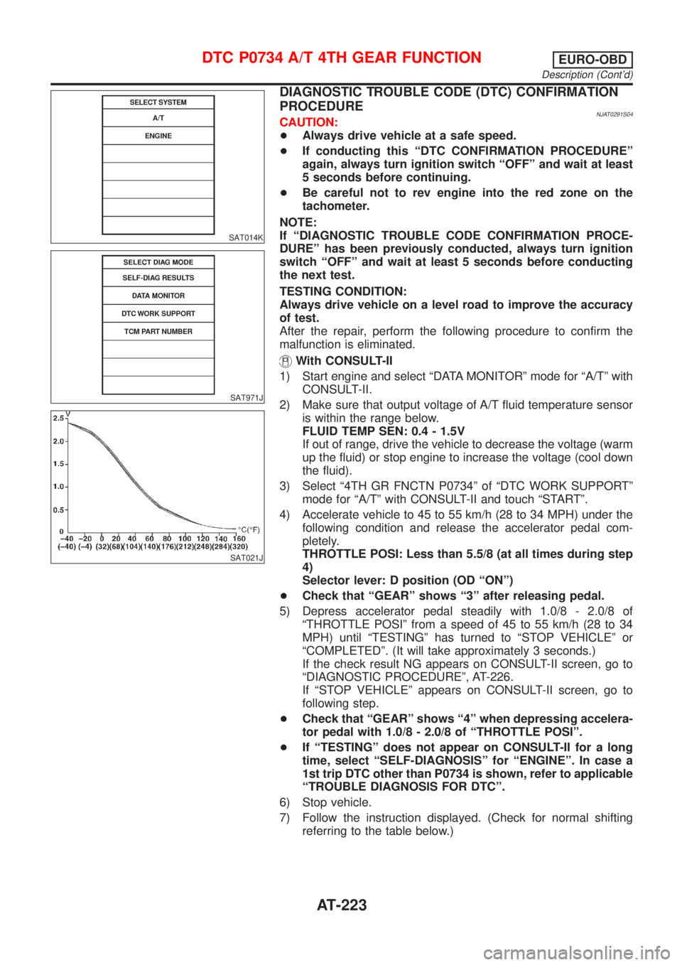
1) Start engine and select ªDATA MONITORº mode for ªA/Tº with
CONSULT-II.
2) Make sure that output voltage of A/T fluid temperature sensor
is within the range below.
FLUID TEMP SEN: 0.4 - 1.5V
If out of range, drive the vehicle to decrease the voltage (warm
up the fluid) or stop engine to increase the voltage (cool down
the fluid).
3) Select ª4TH GR FNCTN P0734º of ªDTC WORK SUPPORTº
mode for ªA/Tº with CONSULT-II and touch ªSTARTº.
4) Accelerate vehicle to 45 to 55 km/h (28 to 34 MPH) under the
following condition and release the accelerator pedal com-
pletely.
THROTTLE POSI: Less than 5.5/8 (at all times during step
4)
Selector lever: D position (OD ªONº)
+Check that ªGEARº shows ª3º after releasing pedal.
5) Depress accelerator pedal steadily with 1.0/8 - 2.0/8 of
ªTHROTTLE POSIº from a speed of 45 to 55 km/h (28 to 34
MPH) until ªTESTINGº has turned to ªSTOP VEHICLEº or
ªCOMPLETEDº. (It will take approximately 3 seconds.)
If the check result NG appears on CONSULT-II screen, go to
ªDIAGNOSTIC PROCEDUREº, AT-226.
If ªSTOP VEHICLEº appears on CONSULT-II screen, go to
following step.
+Check that ªGEARº shows ª4º when depressing accelera-
tor pedal with 1.0/8 - 2.0/8 of ªTHROTTLE POSIº.
+If ªTESTINGº does not appear on CONSULT-II for a long
time, select ªSELF-DIAGNOSISº for ªENGINEº. In case a
1st trip DTC other than P0734 is shown, refer to applicable
ªTROUBLE DIAGNOSIS FOR DTCº.
6) Stop vehicle.
7) Follow the instruction displayed. (Check for normal shifting
referring to the table below.)
DTC P0734 A/T 4TH GEAR FUNCTIONEURO-OBD
Description (Cont'd)
AT-223
Page 1532 of 2493
SAT065K
RemovalNJAT0115CAUTION:
Before separating transaxle from engine, remove the crank-
shaft position sensor (Euro-OBD) from transaxle. Be careful
not to damage sensor.
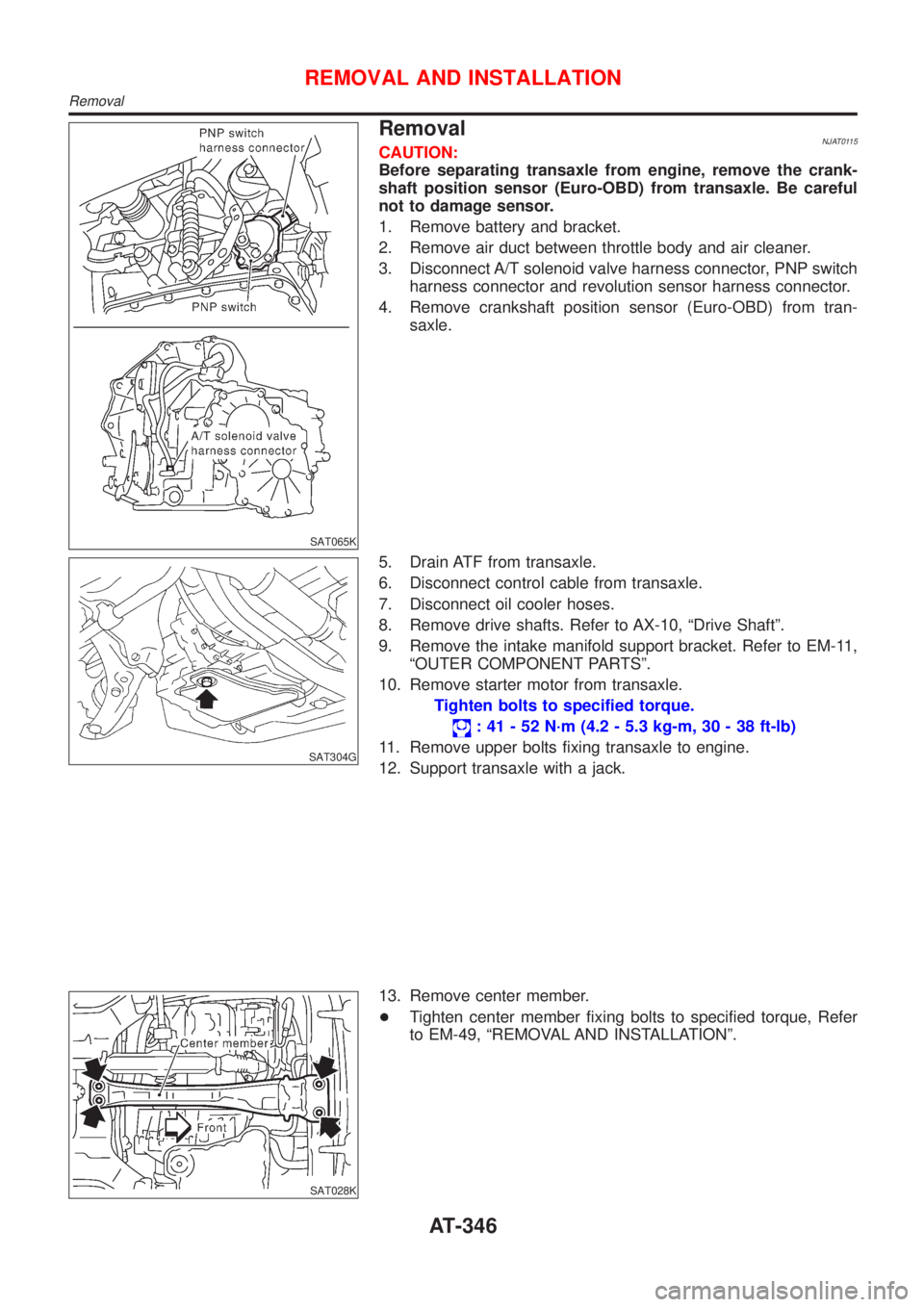
1. Remove battery and bracket.
2. Remove air duct between throttle body and air cleaner.
3. Disconnect A/T solenoid valve harness connector, PNP switch
harness connector and revolution sensor harness connector.
4. Remove crankshaft position sensor (Euro-OBD) from tran-
saxle.
SAT304G
5. Drain ATF from transaxle.
6. Disconnect control cable from transaxle.
7. Disconnect oil cooler hoses.
8. Remove drive shafts. Refer to AX-10, ªDrive Shaftº.
9. Remove the intake manifold support bracket. Refer to EM-11,
ªOUTER COMPONENT PARTSº.
10. Remove starter motor from transaxle.
Tighten bolts to specified torque.
: 41 - 52 N´m (4.2 - 5.3 kg-m, 30 - 38 ft-lb)
11. Remove upper bolts fixing transaxle to engine.
12. Support transaxle with a jack.
SAT028K
13. Remove center member.
+Tighten center member fixing bolts to specified torque, Refer
to EM-49, ªREMOVAL AND INSTALLATIONº.
REMOVAL AND INSTALLATION
Removal
AT-346