Page 923 of 2493
10 CHECK ENGINE COOLANT TEMPERATURE SENSOR
1. Remove engine coolant temperature sensor.
2. Check resistance between engine coolant temperature sensor terminals 1 and 2 as shown in the figure.
SEF304X
OK or NG
OK©GO TO 11.
NG©Replace engine coolant temperature sensor.
11 CHECK MAIN 12 CAUSES
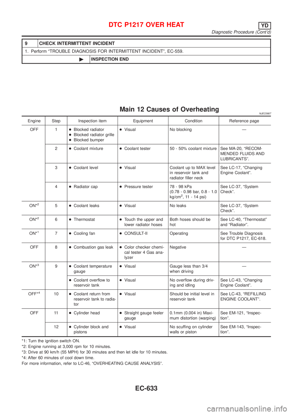
If the cause cannot be isolated, go to ªMAIN 12 CAUSES OF OVERHEATINGº, EC-633.
©INSPECTION END
PROCEDURE ANJEC0666S05
1 CHECK COOLING FAN POWER SUPPLY CIRCUIT
1. Turn ignition switch ªOFFº.
2. Disconnect cooling fan relay-1.
3. Turn ignition switch ªONº.
4. Check voltage between cooling fan relay-1 terminals 2, 3 and ground with CONSULT-II or tester.
SEF899Y
OK or NG
OK©GO TO 3.
NG©GO TO 2.
DTC P1217 OVER HEATYD
Diagnostic Procedure (Cont'd)
EC-627
Page 929 of 2493

9 CHECK INTERMITTENT INCIDENT
1. Perform ªTROUBLE DIAGNOSIS FOR INTERMITTENT INCIDENTº, EC-559.
©INSPECTION END
Main 12 Causes of OverheatingNJEC0667
Engine Step Inspection item Equipment Condition Reference page
OFF 1+Blocked radiator
+Blocked radiator grille
+Blocked bumper+Visual No blocking Ð
2+Coolant mixture+Coolant tester 50 - 50% coolant mixture See MA-20, ªRECOM-
MENDED FLUIDS AND
LUBRICANTSº.
3+Coolant level+Visual Coolant up to MAX level
in reservoir tank and
radiator filler neckSee LC-17, ªChanging
Engine Coolantº.
4+Radiator cap+Pressure tester 78 - 98 kPa
(0.78 - 0.98 bar, 0.8 - 1.0
kg/cm
2, 11 - 14 psi)See LC-37, ªSystem
Checkº.
ON*
25+Coolant leaks+Visual No leaks See LC-37, ªSystem
Checkº.
ON*
26+Thermostat+Touch the upper and
lower radiator hosesBoth hoses should be
hotSee LC-40, ªThermostatº
and ªRadiatorº.
ON*
17+Cooling fan+CONSULT-II Operating See Trouble Diagnosis
for DTC P1217, EC-618.
OFF 8+Combustion gas leak+Color checker chemi-
cal tester 4 Gas ana-
lyzerNegative Ð
ON*
39+Coolant temperature
gauge+Visual Gauge less than 3/4
when drivingÐ
+Coolant overflow to
reservoir tank+Visual No overflow during driv-
ing and idlingSee LC-43, ªChanging
Engine Coolantº.
OFF*
410+Coolant return from
reservoir tank to radia-
tor+Visual Should be initial level in
reservoir tankSee LC-43, ªREFILLING
ENGINE COOLANTº.
OFF 11+Cylinder head+Straight gauge feeler
gauge0.1mm (0.004 in) Maxi-
mum distortion (warping)See EM-121, ªInspec-
tionº.
12+Cylinder block and
pistons+Visual No scuffing on cylinder
walls or pistonSee EM-143, ªInspec-
tionº.
*1: Turn the ignition switch ON.
*2: Engine running at 3,000 rpm for 10 minutes.
*3: Drive at 90 km/h (55 MPH) for 30 minutes and then let idle for 10 minutes.
*4: After 60 minutes of cool down time.
For more information, refer to LC-46, ªOVERHEATING CAUSE ANALYSISº.
DTC P1217 OVER HEATYD
Diagnostic Procedure (Cont'd)
EC-633
Page 973 of 2493

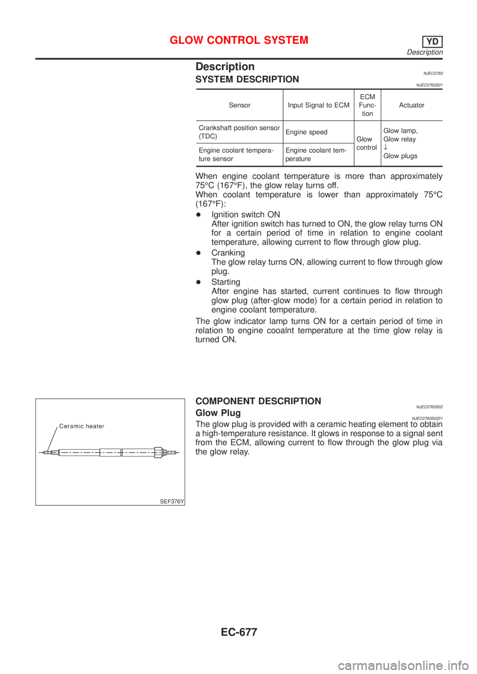
DescriptionNJEC0760SYSTEM DESCRIPTIONNJEC0760S01
Sensor Input Signal to ECMECM
Func-
tionActuator
Crankshaft position sensor
(TDC)Engine speed
Glow
controlGlow lamp,
Glow relay
¯
Glow plugs Engine coolant tempera-
ture sensorEngine coolant tem-
perature
When engine coolant temperature is more than approximately
75ÉC (167ÉF), the glow relay turns off.
When coolant temperature is lower than approximately 75ÉC
(167ÉF):
+Ignition switch ON
After ignition switch has turned to ON, the glow relay turns ON
for a certain period of time in relation to engine coolant
temperature, allowing current to flow through glow plug.
+Cranking
The glow relay turns ON, allowing current to flow through glow
plug.
+Starting
After engine has started, current continues to flow through
glow plug (after-glow mode) for a certain period in relation to
engine coolant temperature.
The glow indicator lamp turns ON for a certain period of time in
relation to engine cooalnt temperature at the time glow relay is
turned ON.
SEF376Y
COMPONENT DESCRIPTIONNJEC0760S02Glow PlugNJEC0760S0201The glow plug is provided with a ceramic heating element to obtain
a high-temperature resistance. It glows in response to a signal sent
from the ECM, allowing current to flow through the glow plug via
the glow relay.
GLOW CONTROL SYSTEMYD
Description
EC-677
Page 977 of 2493
4 CHECK GLOW INDICATOR LAMP OPERATION
Without CONSULT-II
1. Turn ignition switch ªONº.
2. Confirm that the voltage between ECM terminal 347 (Engine coolant temperature sensor signal) and ground is above
1.36V. If it is below 1.36V, cool down engine.
SEF442Z
3. Turn ignition switch ªOFFº, wait at least 5 seconds and then turn ªONº.
4. Make sure that glow indicator lamp is turned ªONº for 1.5 seconds or more after turning ignition switch ªONº, and then
turned ªOFFº.
OK or NG
OK©GO TO 5.
NG©GO TO 6.
5 CHECK GLOW CONTROL SYSTEM OVERALL FUNCTION
1. Turn ignition switch ªOFFº.
2. Set voltmeter probe between glow plug and engine body.
3. Turn ignition switch ªONº.
4. Check the voltage between glow plug and engine body under the following conditions.
SEF431Y
OK or NG
OK©INSPECTION END
NG©GO TO 11.
GLOW CONTROL SYSTEMYD
Diagnostic Procedure (Cont'd)
EC-681
Page 982 of 2493

DescriptionNJEC0764SYSTEM DESCRIPTIONNJEC0764S01
Sensor Input Signal to ECM ECM Function Actuator
Electronic controlled fuel injection pump Fuel injection signal
EGR volume con-
trolEGR volume control
valve Crankshaft position sensor (TDC) Engine speed
Vehicle speed sensor Vehicle speed
Engine coolant temperature sensor Engine coolant temperature
Ignition switch Start signal
Accelerator position sensor Accelerator position
Mass air flow sensor Amount of intake air
Air conditioner switch Air conditioner operation
Electrical load Electrical load signal
This system controls flow rate of EGR led from exhaust manifold
to intake manifold. The opening of the EGR by-pass passage in the
EGR volume control valve changes to control the flow rate. A
built-in step motor moves the valve in steps corresponding to the
ECM output pulses. The opening of the valve varies for optimum
engine control. The optimum value stored in the ECM is determined
by considering various engine conditions.
The EGR volume control valve remains close under the following
conditions.
+Engine stopped
+Engine starting
+Low engine coolant temperature
+Excessively high engine coolant temperature
+High engine speed
+Wide open throttle
SEF908Y
SEF411Y
COMPONENT DESCRIPTIONNJEC0764S02EGR Volume Control ValveNJEC0764S0201The EGR volume control valve uses a step motor to control the flow
rate of EGR from exhaust manifold. This motor has four winding
phases. It operates according to the output pulse signal of the
ECM. Two windings are turned ON and OFF in sequence. Each
time an ON pulse is issued, the valve opens or closes, changing
the flow rate. When no change in the flow rate is needed, the ECM
does not issue the pulse signal. A certain voltage signal is issued
so that the valve remains at that particular opening.
EGR VOLUME CONTROL SYSTEMYD
Description
EC-686
Page 998 of 2493
General SpecificationsNJEC0788Unit: rpm
Engine YD22DDT
Idle speed 725±25
Maximum engine speed 4,900
Injection NozzleNJEC0790Unit: kPa (bar, kg/cm2, psi)
Initial injection pressureNew 21,476 - 22,457 (214.7 - 224.5, 219 - 229, 3,114 - 3,256)
Limit 18,275 (182.7, 186, 2,650)
Engine Coolant Temperature SensorNJEC0791
Temperature ÉC (ÉF) Resistance kW
20 (68) 2.1 - 2.9
50 (122) 0.68 - 1.00
90 (194) 0.236 - 0.260
Crankshaft Position Sensor (TDC)NJEC0792
Resistance [at 20ÉC (68ÉF)]W495 - 605
Glow PlugNJEC0793
Resistance [at 25ÉC (77ÉF)]W0.8
Accelerator Position SensorNJEC0794
Throttle valve conditions Resistance between terminals 2 and 4 kW[at 25ÉC (77ÉF)]
Completely closed0.9 - 1.3
Partially open0.9 - 2.1
Completely open1.7 - 2.1
EGR Volume Control ValveNJEC0795
Resistance [at 25ÉC (77ÉF)]W13-17
SERVICE DATA AND SPECIFICATIONS (SDS)YD
General Specifications
EC-702
Page 1235 of 2493

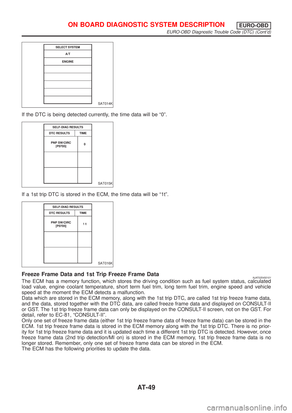
SAT014K
If the DTC is being detected currently, the time data will be ª0º.
SAT015K
If a 1st trip DTC is stored in the ECM, the time data will be ª1tº.
SAT016K
Freeze Frame Data and 1st Trip Freeze Frame DataNJAT0254S0101The ECM has a memory function, which stores the driving condition such as fuel system status, calculated
load value, engine coolant temperature, short term fuel trim, long term fuel trim, engine speed and vehicle
speed at the moment the ECM detects a malfunction.
Data which are stored in the ECM memory, along with the 1st trip DTC, are called 1st trip freeze frame data,
and the data, stored together with the DTC data, are called freeze frame data and displayed on CONSULT-II
or GST. The 1st trip freeze frame data can only be displayed on the CONSULT-II screen, not on the GST. For
detail, refer to EC-81, ªCONSULT-IIº.
Only one set of freeze frame data (either 1st trip freeze frame data of freeze frame data) can be stored in the
ECM. 1st trip freeze frame data is stored in the ECM memory along with the 1st trip DTC. There is no prior-
ity for 1st trip freeze frame data and it is updated each time a different 1st trip DTC is detected. However, once
freeze frame data (2nd trip detection/MI on) is stored in the ECM memory, 1st trip freeze frame data is no
longer stored. Remember, only one set of freeze frame data can be stored in the ECM.
The ECM has the following priorities to update the data.
ON BOARD DIAGNOSTIC SYSTEM DESCRIPTIONEURO-OBD
EURO-OBD Diagnostic Trouble Code (DTC) (Cont'd)
AT-49
Page 2202 of 2493

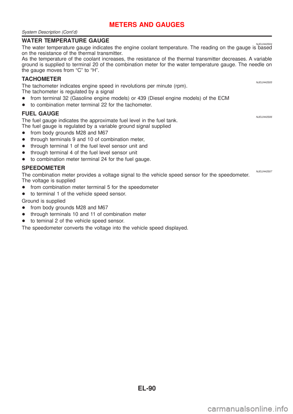
WATER TEMPERATURE GAUGENJEL0442S04The water temperature gauge indicates the engine coolant temperature. The reading on the gauge is based
on the resistance of the thermal transmitter.
As the temperature of the coolant increases, the resistance of the thermal transmitter decreases. A variable
ground is supplied to terminal 20 of the combination meter for the water temperature gauge. The needle on
the gauge moves from ªCº to ªHº.
TACHOMETERNJEL0442S05The tachometer indicates engine speed in revolutions per minute (rpm).
The tachometer is regulated by a signal
+from terminal 32 (Gasoline engine models) or 439 (Diesel engine models) of the ECM
+to combination meter terminal 22 for the tachometer.
FUEL GAUGENJEL0442S06The fuel gauge indicates the approximate fuel level in the fuel tank.
The fuel gauge is regulated by a variable ground signal supplied
+from body grounds M28 and M67
+through terminals 9 and 10 of combination meter,
+through terminal 1 of the fuel level sensor unit and
+through terminal 4 of the fuel level sensor unit
+to combination meter terminal 24 for the fuel gauge.
SPEEDOMETERNJEL0442S07The combination meter provides a voltage signal to the vehicle speed sensor for the speedometer.
The voltage is supplied
+from combination meter terminal 5 for the speedometer
+to terminal 1 of the vehicle speed sensor.
Ground is supplied
+from body grounds M28 and M67
+through terminals 10 and 11 of combination meter
+to teminal 2 of the vehicle speed sensor.
The speedometer converts the voltage into the vehicle speed displayed.
METERS AND GAUGES
System Description (Cont'd)
EL-90