2001 LAND ROVER FREELANDER clock
[x] Cancel search: clockPage 25 of 1007

CONTENTS
22 CONTENTS
NAVIGATION SYSTEM ............................................................................ 87-1
REPAIRS
Interface unit - remote control ........................................................................................................ 87-1
Display unit - navigation system .................................................................................................... 87-1
INSTRUMENTS ......................................................................................... 88-1
REPAIRS
Clock .............................................................................................................................................. 88-1
Instrument panel - up to 04MY ....................................................................................................... 88-2
Instrument panel - from 04MY ........................................................................................................ 88-3
Cowl - instrument - up to 04MY ...................................................................................................... 88-4
Cowl - instrument - from 04MY ....................................................................................................... 88-5
Sender unit - fuel tank gauge.......................................................................................................... 88-6
Sender unit assembly - fuel tank - Td4 models - from 03MY.......................................................... 88-6
Page 44 of 1007

GENERAL INFORMATION
03-13
Self-locking bolts and screws
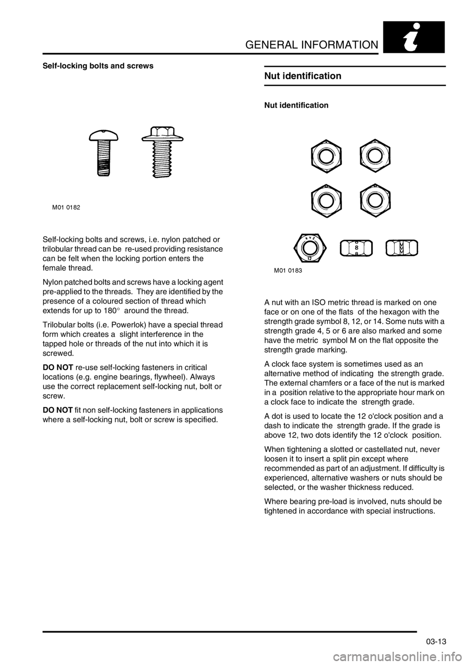
Self-locking bolts and screws, i.e. nylon patched or
trilobular thread can be re-used providing resistance
can be felt when the locking portion enters the
female thread.
Nylon patched bolts and screws have a locking agent
pre-applied to the threads. They are identified by the
presence of a coloured section of thread which
extends for up to 180° around the thread.
Trilobular bolts (i.e. Powerlok) have a special thread
form which creates a slight interference in the
tapped hole or threads of the nut into which it is
screwed.
DO NOT re-use self-locking fasteners in critical
locations (e.g. engine bearings, flywheel). Always
use the correct replacement self-locking nut, bolt or
screw.
DO NOT fit non self-locking fasteners in applications
where a self-locking nut, bolt or screw is specified.
Nut identification
Nut identification
A nut with an ISO metric thread is marked on one
face or on one of the flats of the hexagon with the
strength grade symbol 8, 12, or 14. Some nuts with a
strength grade 4, 5 or 6 are also marked and some
have the metric symbol M on the flat opposite the
strength grade marking.
A clock face system is sometimes used as an
alternative method of indicating the strength grade.
The external chamfers or a face of the nut is marked
in a position relative to the appropriate hour mark on
a clock face to indicate the strength grade.
A dot is used to locate the 12 o'clock position and a
dash to indicate the strength grade. If the grade is
above 12, two dots identify the 12 o'clock position.
When tightening a slotted or castellated nut, never
loosen it to insert a split pin except where
recommended as part of an adjustment. If difficulty is
experienced, alternative washers or nuts should be
selected, or the washer thickness reduced.
Where bearing pre-load is involved, nuts should be
tightened in accordance with special instructions.
Page 64 of 1007

GENERAL DATA
04-1
GENERAL DATA
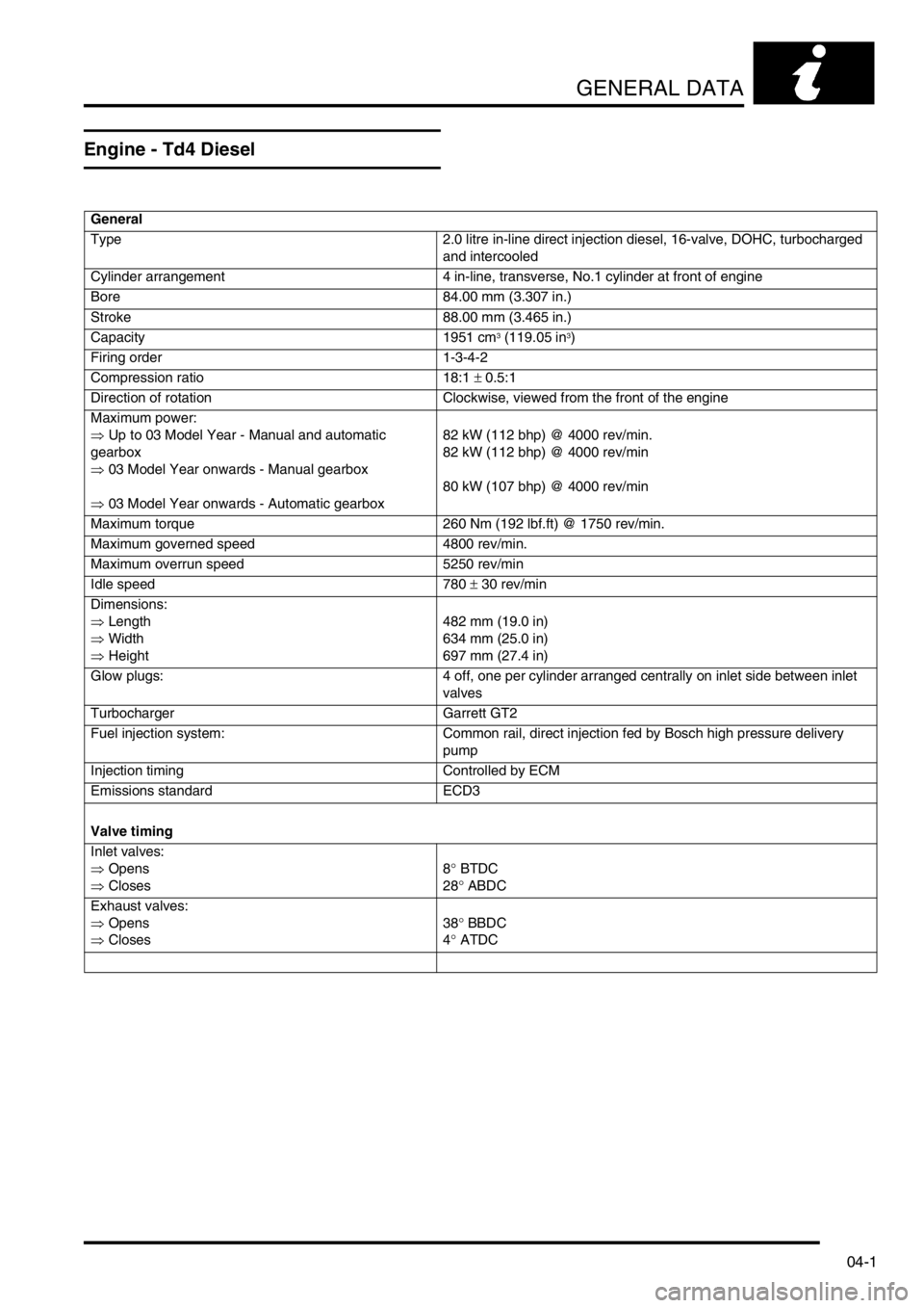
Engine - Td4 Diesel
General
Type 2.0 litre in-line direct injection diesel, 16-valve, DOHC, turbocharged
and intercooled
Cylinder arrangement 4 in-line, transverse, No.1 cylinder at front of engine
Bore 84.00 mm (3.307 in.)
Stroke 88.00 mm (3.465 in.)
Capacity 1951 cm
3 (119.05 in3)
Firing order 1-3-4-2
Compression ratio 18:1 ± 0.5:1
Direction of rotation Clockwise, viewed from the front of the engine
Maximum power:
⇒ Up to 03 Model Year - Manual and automatic
gearbox
⇒ 03 Model Year onwards - Manual gearbox
⇒ 03 Model Year onwards - Automatic gearbox82 kW (112 bhp) @ 4000 rev/min.
82 kW (112 bhp) @ 4000 rev/min
80 kW (107 bhp) @ 4000 rev/min
Maximum torque 260 Nm (192 lbf.ft) @ 1750 rev/min.
Maximum governed speed 4800 rev/min.
Maximum overrun speed 5250 rev/min
Idle speed 780 ± 30 rev/min
Dimensions:
⇒ Length
⇒ Width
⇒ Height482 mm (19.0 in)
634 mm (25.0 in)
697 mm (27.4 in)
Glow plugs: 4 off, one per cylinder arranged centrally on inlet side between inlet
valves
Turbocharger Garrett GT2
Fuel injection system: Common rail, direct injection fed by Bosch high pressure delivery
pump
Injection timing Controlled by ECM
Emissions standard ECD3
Valve timing
Inlet valves:
⇒ Opens
⇒ Closes8° BTDC
28° ABDC
Exhaust valves:
⇒ Opens
⇒ Closes38° BBDC
4° ATDC
Page 69 of 1007

GENERAL DATA
04-6
Engine - K1.8 Petrol
General
Type 1.8 litre petrol, 16-valve DOHC
Cylinder arrangement 4 in-line, transverse, No.1 cylinder at front of engine
Bore 80.00 mm (3.150 in.)
Stroke 89.30 mm (3.516 in.)
Capacity 1796 cm
3 (109.59 in3)
Firing order 1-3-4-2
Compression ratio 10.5 :1 ± 0.5 :1
Direction of rotation Clockwise viewed from the front of the engine
Maximum power 88 kW (118 bhp) @ 5500 rev/min.
Maximum torque 165 Nm (223.7 lbf.ft) @ 2750 rev/min.
Idle speed 775 ± 50 rev/min.
Maximum intermittent engine speed 6750 rev/min.
Weight (fully dressed, wet) 108 kg (238 lb)
Dimensions:
⇒ Length (nominal) 654 mm (25.75 in.)
⇒ Width (nominal) 600 mm (23.62 in.)
⇒ Height (nominal) 615 mm (24.21 in.)
Spark plugs:
⇒ Type NLP 100290
⇒ Gap 1.0 mm ± 0.05 mm (0.039 in. ± 0.002 in.)
Ignition coils:
⇒ Make Nippon Denso - NEC 100730
⇒ Type 2 x twin output coils, plug top mounted; cylinders 1 & 4 and 2 & 3
⇒ Primary resistance (typical) 0.7 Ω
⇒ Secondary resistance (typical) 10 Ω
Fuel injection system:
Type Returnless fuel rail, multi-point fuel injection, electronically controlled
from ECM
Controller MEMS 3 breakerless, electronic, fully mapped engine management
system
Injectors:
⇒ Operating pressure 3.5 bar (50.8 lbf.in
2)
⇒ Fuel flow rate 117 g/min. @ 3.0 bar (4.13 fl.oz/min. @ 43.5 lbf. in
2)
Valve operation Self-adjusting, lightweight hydraulic tappets operated directly by
camshafts
Emissions standard ECD3
Cylinder block:
Material Aluminium alloy
Cylinder liner type Damp, bottom half stepped - sliding fit into lower part of cylinder block
Cylinder liner bore:
⇒ RED grade A 80.000 - 80.015 mm (3.1496 - 3.1501 in.)
⇒ BLUE grade B 80.016 - 80.030 mm (3.1502 - 3.1508 in.)
Page 74 of 1007

GENERAL DATA
04-11
Engine - KV6 Petrol
General
Type:
⇒ Up to 03 Model Year
⇒ From 03 Model Year2.5 litre V6, 24 valve, air assisted direct fuel injection petrol, water
cooled, transverse mounted
2.5 litre V6, 24 valve, direct fuel injection petrol, water cooled,
transverse mounted
Cylinder arrangement: 90° V6, numbered from the front of the engine
⇒ Left bank Cylinders 1, 3 and 5
⇒ Right bank Cylinders 2, 4 and 6
Bore (nominal) 80 mm (3.15 in.)
Stroke 82.8 mm (3.26 in.)
Capacity 2497 cm
3 (152.37 in3)
Firing order 1-6-5-4-3-2
Compression ratio 10.5 : 1 ± 0.5 : 1
Direction of rotation Clockwise viewed from front of engine
Maximum power 130 kW (177 bhp) @ 6500 rev/min.
Maximum torque 240.0 Nm (177 lbf.ft) @ 4000 rev/min.
Maximum engine speed:
⇒ Continuous 6500 rev/min.
⇒ Intermittent 6750 rev/min.
Idle speed 750 rev/min. ± 50 rev/min.
Weight (fully dressed, wet) 154 kg (340 lb)
Dimensions (dressed):
⇒ Length (nominal) 770 mm (30.3 in.)
⇒ Width (nominal) 750 mm (29.5 in.)
⇒ Height (nominal) 750 mm (29.5 in.)
Valve operation Self-adjusting lightweight hydraulic tappets operated directly by the
camshafts
Fuel injection system:
⇒ Make - Up to 03 Model Year
⇒ Make - From 03 Model YearSiemens engine management system
Siemens engine management system
⇒ Type - Up to 03 Model Year
⇒ Type - From 03 Model YearMulti-point, air assisted fuel injection controlled by ECM, electro-
mechanical injectors with twin sprays targeted on to back of inlet
valves
Multi-point fuel injection controlled by ECM, electro-mechanical
injectors with quadruple sprays targeted on to back of inlet valves
Inlet manifold Variable geometry
Spark plugs
⇒ Type
⇒ Plug gapNLP 100290
1.0 mm ± 0.05 mm (0.039 in. ± 0.002 in.)
Coils:
⇒ Make - Up to 03 Model Year
⇒ Make - From 03 Model Year
⇒ Type - Up to 03 Model Year
⇒ Type - From 03 Model YearBREMR
Champion BAE 403H
6 x coils (3 x plug top, 3 x remote mounted)
6 x coils (6 x plug top)
Emissions standard ECD3
Page 213 of 1007

ENGINE - K SERIES KV6
12-3-36 REPAIRS
17.Rotate heated front screen relay anti-clockwise
and release it from 'E' box bracket.
18.Release 4 clips and remove carrier from 'E' box.
19.Remove nut, release retainer and remove 'E'
box.20.Remove engine compartment fuse box cover.
21.Remove 2 bolts securing battery and starter
lead to fuse box.
22.Disconnect multiplug from fuse box.
23.Disconnect earth header multiplug.
24.Release 3 clips securing engine harness to 'E'
box mounting bracket, lay harness over engine.
M12 6765
M12 6766
Page 235 of 1007

ENGINE - K SERIES KV6
12-3-58 REPAIRS
Camshaft timing belt
$% 12.65.18
Remove
1.Disconnect battery earth lead.
2.Remove ancillary drive belt.
+ CHARGING AND STARTING,
REPAIRS, Ancillary drive belt - KV6.
3.Remove RH front road wheel.
4.Remove 3 bolts securing RH splash shield to
body and remove shield.
5.Remove 3 bolts securing camshaft timing belt
LH rear cover and remove cover.
6.Remove inlet manifold chamber.
+ MANIFOLDS & EXHAUST SYSTEMS
- K SERIES KV6, REPAIRS, Seals - inlet
manifold chamber - up to 03MY.
+ MANIFOLDS & EXHAUST SYSTEMS
- K SERIES KV6, REPAIRS, Seals - inlet
manifold chamber - from 03MY.7.Remove 2 bolts securing RH rear timing belt
cover heat shield; remove heat shield.
8.Remove 3 bolts securing RH rear timing belt
cover; remove cover.
9.Using a socket on crankshaft pulley bolt, rotate
crankshaft in a clockwise direction. Align the
engine "SAFE" position, notch on crankshaft
pulley with the "ARROW" on front mounting
plate and the timing marks aligned on the rear
camshaft gears as illustrated.
CAUTION: Do not use camshaft gear bolts
or timing belt to rotate crankshaft.
M12 6614
M12 6694
Page 241 of 1007

ENGINE - K SERIES KV6
12-3-64 REPAIRS
Refit
NOTE: Following front or rear timing belt
refitment, it is possible that, after rotating the
engine and positioning the crankshaft pulley to
the 'SAFE' position, the timing marks on the
rear timing gears may be misaligned. This
misalignment is acceptable provided that the
timing belt refitting procedure was carried out
correctly.
1.Clean camshaft gears and hubs, crankshaft
gear, tensioner and water pump pulleys.
CAUTION: If the sintered gears have been
subjected to prolonged oil contamination,
they must be soaked in a solvent bath and
then thoroughly washed in clean solvent
before refitting. Because of the porous
construction of sintered material, oil
impregnated in the gears will emerge and
contaminate the belt.
2.Fit hubs to camshaft gears and fit gears to
camshafts. Fit new bolts and tighten sufficiently
to allow gears to rotate without tipping.
3.Position timing belt to crankshaft gear.
NOTE: To prevent the timing belt from
disengaging from the crankshaft gear when
fitting, fit a suitable wedge between the belt and
oil pump belt guard.
4.Fit tool LRT-12-197 into each exhaust
camshaft in turn.5.Using assistance, rotate each exhaust
camshaft slightly and align timing marks on LH
and RH rear camshaft gears.
6.Remove tool LRT-12-197 from exhaust
camshaft.
7.Fit tools LRT-12-175 to LH and RH rear
camshaft gears.
8.Rotate both front inlet camshaft gears fully
clockwise as viewed from front of engine.
9.Using fingers only, fit timing belt to gears,
starting at the crankshaft gear and working in
an anti-clockwise direction, keeping the belt run
as taut as possible and turning the camshaft
gears only a minimum amount anti-clockwise to
fit timing belt.
CAUTION: Gears must not be rotated anti-
clockwise more than one tooth.
10.Position an Allen key in tensioner backplate
and hold tensioner pulley against timing belt.