Page 2279 of 2395

Listen to Customer ComplaintsNBTF0015IEach customer feels differently about a problem. It is important
to fully understand the symptoms or conditions for a customer
complaint.
IListen to the customer about how and when the malfunction
occurs, and make good use of it when performing the road test.
Transfer Fluid CheckNBTF0016ICheck fluid for leaks and fluid level. Refer to MA-22, ªCheck-
ing All-mode 4WD Transfer Fluidº.
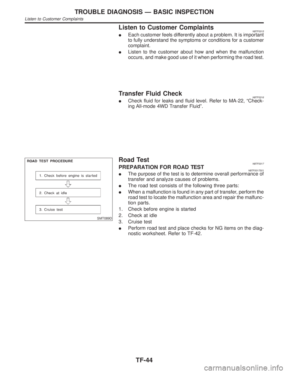
SMT089D
Road TestNBTF0017PREPARATION FOR ROAD TESTNBTF0017S01IThe purpose of the test is to determine overall performance of
transfer and analyze causes of problems.
IThe road test consists of the following three parts:
IWhen a malfunction is found in any part of transfer, perform the
road test to locate the malfunction area and repair the malfunc-
tion parts.
1. Check before engine is started
2. Check at idle
3. Cruise test
IPerform road test and place checks for NG items on the diag-
nostic worksheet. Refer to TF-42.
TROUBLE DIAGNOSIS Ð BASIC INSPECTION
Listen to Customer Complaints
TF-44
Page 2280 of 2395
1. CHECK BEFORE ENGINE IS STARTED=NBTF0017S02
1 CHECK 4WD SHIFT INDICATOR LAMP
1. Park vehicle on flat surface.
2. Turn ignition switch to ªOFFº position.
3. Move A/T selector lever to ªPº position.
4. Set 4WD shift switch to ª4Hº position.
SMT849D
5. Set 4WD shift switch to ª2WDº position.
6. Turn ignition switch to ªONº position. (Do not start engine.)
7. Does 4WD shift indicator lamp turn ON for approx. 1 second?
SMT958D
YesorNo
Ye s©GO TO 2.
No©Go to Symptom 1. Refer to TF-98.
GI
MA
EM
LC
EC
FE
AT
PD
AX
SU
BR
ST
RS
BT
HA
SC
EL
IDX
TROUBLE DIAGNOSIS Ð BASIC INSPECTION
Road Test (Cont'd)
TF-45
Page 2282 of 2395
2. CHECK AT IDLE=NBTF0017S03
1 CHECK 4WD SHIFT INDICATOR LAMP
1. Park vehicle on flat surface.
2. Turn ignition switch to ªOFFº position.
3. Move A/T selector lever to ªPº or ªNº position.
4. Set 4WD shift switch to ª4Hº position.
5. Set 4WD shift switch to ª2WDº position.
6. Start engine.
7. Is 4WD shift indicator lamp turned OFF?
SMT958D
YesorNo
Ye s©Go to ªATP SWITCH, WAIT DETECTION SWITCH AND NEUTRAL-4LO SWITCHº. Refer
to TF-76.
No©GO TO 2.
2 CHECK 4WD WARNING LAMP
Is 4WD warning lamp turned OFF?
YesorNo
Ye s©GO TO 3.
No©Perform self-diagnosis. Refer to ªTrouble Diagnosis without CONSULT-IIº, TF-27.
GI
MA
EM
LC
EC
FE
AT
PD
AX
SU
BR
ST
RS
BT
HA
SC
EL
IDX
TROUBLE DIAGNOSIS Ð BASIC INSPECTION
Road Test (Cont'd)
TF-47
Page 2287 of 2395

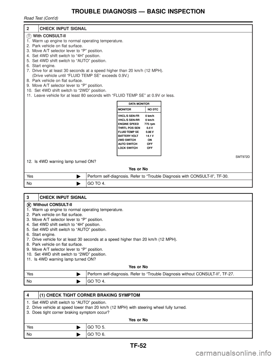
2 CHECK INPUT SIGNAL
With CONSULT-II
1. Warm up engine to normal operating temperature.
2. Park vehicle on flat surface.
3. Move A/T selector lever to ªPº position.
4. Set 4WD shift switch to ª4Hº position.
5. Set 4WD shift switch to ªAUTOº position.
6. Start engine.
7. Drive for at least 30 seconds at a speed higher than 20 km/h (12 MPH).
(Drive vehicle until ªFLUID TEMP SEº exceeds 0.9V.)
8. Park vehicle on flat surface.
9. Move A/T selector lever to ªPº position.
10. Set 4WD shift switch to ª2WDº position.
11. Leave vehicle for at least 80 seconds with ªFLUID TEMP SEº at 0.9V or less.
SMT972D
12. Is 4WD warning lamp turned ON?
YesorNo
Ye s©Perform self-diagnosis. Refer to ªTrouble Diagnosis with CONSULT-IIº, TF-30.
No©GO TO 4.
3 CHECK INPUT SIGNAL
Without CONSULT-II
1. Warm up engine to normal operating temperature.
2. Park vehicle on flat surface.
3. Move A/T selector lever to ªPº position.
4. Set 4WD shift switch to ª4Hº position.
5. Set 4WD shift switch to ªAUTOº position.
6. Start engine.
7. Drive vehicle for at least 30 seconds at a speed higher than 20 km/h (12 MPH).
8. Park vehicle on flat surface.
9. Move A/T selector lever to ªPº position.
10. Set 4WD shift switch to ª2WDº position.
11. Is 4WD warning lamp turned ON?
YesorNo
Ye s©Perform self-diagnosis. Refer to ªTrouble Diagnosis without CONSULT-IIº, TF-27.
No©GO TO 4.
4 (1) CHECK TIGHT CORNER BRAKING SYMPTOM
1. Set 4WD shift switch to ªAUTOº position.
2. Drive vehicle at speed lower than 20 km/h (12 MPH) with steering wheel fully turned.
3. Does tight corner braking symptom occur?
YesorNo
Ye s©GO TO 5.
No©GO TO 6.
TROUBLE DIAGNOSIS Ð BASIC INSPECTION
Road Test (Cont'd)
TF-52
Page 2290 of 2395

SMT772D
TRANSFER CONTROL UNIT INSPECTION TABLENBTF0018S02(Data are reference values.)
Terminal
No.Item Condition Judgement standard
12-4WD shift solenoid
valve
&
4WD shift switch is set to ª2WDº
position.Less than 1V
4WD shift switch is set to any posi-
tion other than ª2WDº.Battery voltage
24WD shift indicator lamp
(2WD)
Lamp lights while system is operating
properly.Less than 1V
&
2WD indicator lamp does not come
on.Battery voltage
3 Ground Ð Ð
4Transfer shift relay
(High)While actuator is operating
(4H,4LO)Battery voltage
Actuator does not operate. Less than 1V
5 4WD warning lampLamp comes ON. (when engine is
stopped.)
(Fail-safe condition appears on
display, engine is stopped, actuator
position detection switch is
inoperative, oil temperature is too
high and/or tires of different size are
installed.)Less than 1V
Except above Battery voltage
6 Ground Ð Ð Ð
7 PNP switch (R position)
&
A/T selector lever is set to ªreverseº
position.Battery voltage
A/T selector lever is set to any posi-
tion other than ªreverseº.Less than 1V
8ÐÐÐÐ
GI
MA
EM
LC
EC
FE
AT
PD
AX
SU
BR
ST
RS
BT
HA
SC
EL
IDX
TROUBLE DIAGNOSIS Ð GENERAL DESCRIPTION
Transfer Control Unit Terminals and Reference Value (Cont'd)
TF-55
Page 2297 of 2395
4 CHECK INPUT SIGNAL
With CONSULT-II
1. Start engine.
2. Select ªECU INPUT SIGNALSº in Data Monitor.
3. Read out the value of ªVEHICLE SPEED SENSOR (FRONT)º while driving.
SMT773D
SMT974D
4. Check if the value changes according to accelerating and decelerating the vehicle.
OK or NG
OK©GO TO 6.
NG©GO TO 7.
VEHICLE SPEED SENSOR (FRONT REVOLUTION SENSOR)
Diagnostic Procedure (Cont'd)
TF-62
Page 2298 of 2395

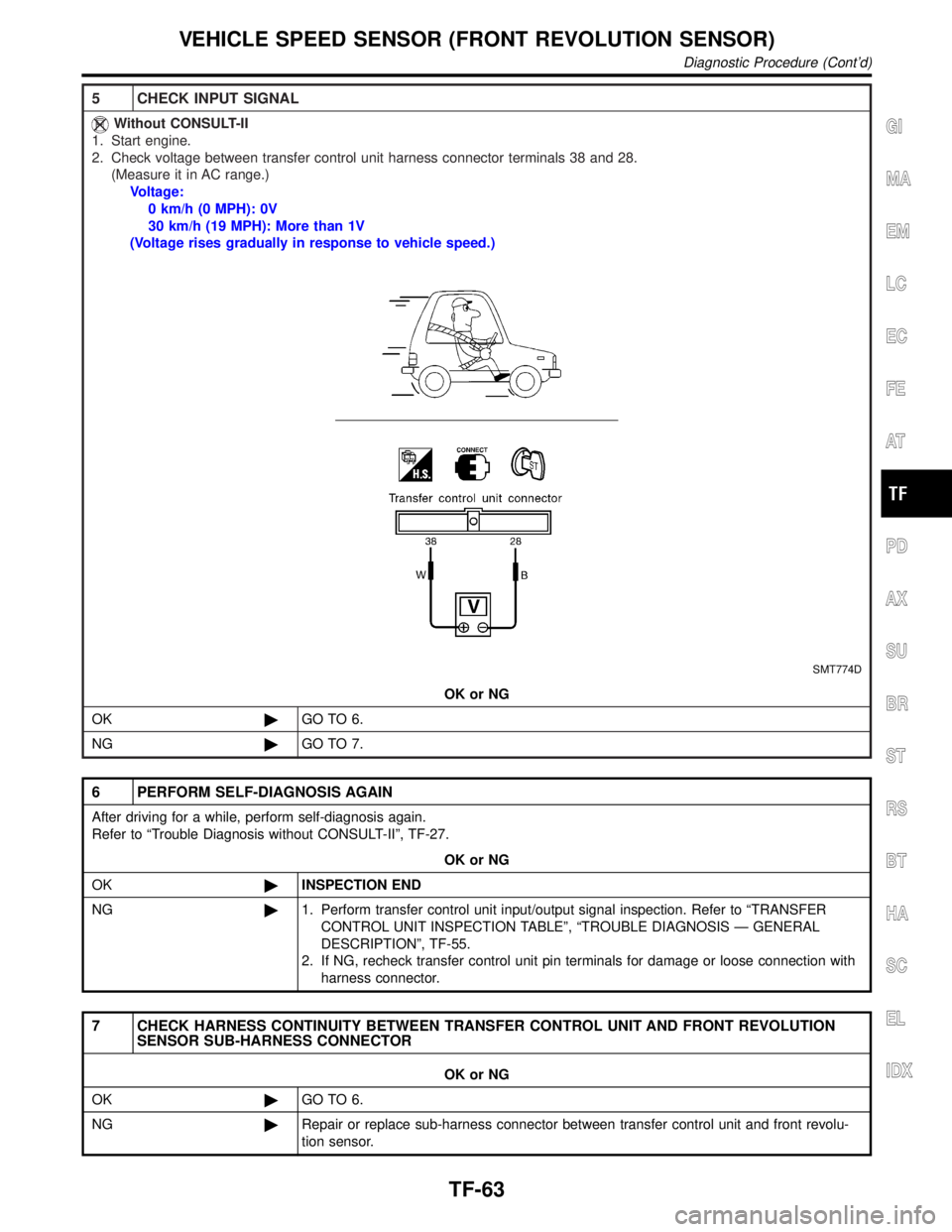
5 CHECK INPUT SIGNAL
Without CONSULT-II
1. Start engine.
2. Check voltage between transfer control unit harness connector terminals 38 and 28.
(Measure it in AC range.)
Voltage:
0 km/h (0 MPH): 0V
30 km/h (19 MPH): More than 1V
(Voltage rises gradually in response to vehicle speed.)
SMT774D
OK or NG
OK©GO TO 6.
NG©GO TO 7.
6 PERFORM SELF-DIAGNOSIS AGAIN
After driving for a while, perform self-diagnosis again.
Refer to ªTrouble Diagnosis without CONSULT-IIº, TF-27.
OK or NG
OK©INSPECTION END
NG©1. Perform transfer control unit input/output signal inspection. Refer to ªTRANSFER
CONTROL UNIT INSPECTION TABLEº, ªTROUBLE DIAGNOSIS Ð GENERAL
DESCRIPTIONº, TF-55.
2. If NG, recheck transfer control unit pin terminals for damage or loose connection with
harness connector.
7 CHECK HARNESS CONTINUITY BETWEEN TRANSFER CONTROL UNIT AND FRONT REVOLUTION
SENSOR SUB-HARNESS CONNECTOR
OK or NG
OK©GO TO 6.
NG©Repair or replace sub-harness connector between transfer control unit and front revolu-
tion sensor.
GI
MA
EM
LC
EC
FE
AT
PD
AX
SU
BR
ST
RS
BT
HA
SC
EL
IDX
VEHICLE SPEED SENSOR (FRONT REVOLUTION SENSOR)
Diagnostic Procedure (Cont'd)
TF-63
Page 2309 of 2395
4 CHECK INPUT SIGNAL
SMT784D
With CONSULT-II
1. Start engine.
2. Select ªECU INPUT SIGNALSº in Data Monitor.
3. Read out the value of ªFLUID TEMP SEº.
Voltage:
20ÉC (68ÉF): Approx. 1.5V
80ÉC (176ÉF): Approx. 0.5V
SMT974D
OK or NG
OK©GO TO 6.
NG©Check the following.
IContinuity between transfer control unit and transfer terminal cord assembly sub-har-
ness connector
TRANSFER FLUID TEMPERATURE SENSOR
Diagnostic Procedure (Cont'd)
TF-74