2001 INFINITI QX4 engine
[x] Cancel search: enginePage 2221 of 2395
SFA975B
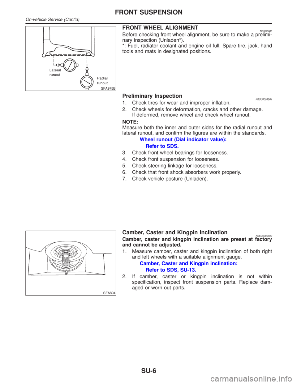
FRONT WHEEL ALIGNMENTNBSU0006Before checking front wheel alignment, be sure to make a prelimi-
nary inspection (Unladen*).
*: Fuel, radiator coolant and engine oil full. Spare tire, jack, hand
tools and mats in designated positions.
Preliminary InspectionNBSU0006S011. Check tires for wear and improper inflation.
2. Check wheels for deformation, cracks and other damage.
If deformed, remove wheel and check wheel runout.
NOTE:
Measure both the inner and outer sides for the radial runout and
lateral runout, and confirm the figures are within the standards.
Wheel runout (Dial indicator value):
Refer to SDS.
3. Check front wheel bearings for looseness.
4. Check front suspension for looseness.
5. Check steering linkage for looseness.
6. Check that front shock absorbers work properly.
7. Check vehicle posture (Unladen).
SFA894
Camber, Caster and Kingpin InclinationNBSU0006S02Camber, caster and kingpin inclination are preset at factory
and cannot be adjusted.
1. Measure camber, caster and kingpin inclination of both right
and left wheels with a suitable alignment gauge.
Camber, Caster and Kingpin inclination:
Refer to SDS, SU-13.
2. If camber, caster or kingpin inclination is not within
specification, inspect front suspension parts. Replace dam-
aged or worn out parts.
FRONT SUSPENSION
On-vehicle Service (Cont'd)
SU-6
Page 2228 of 2395
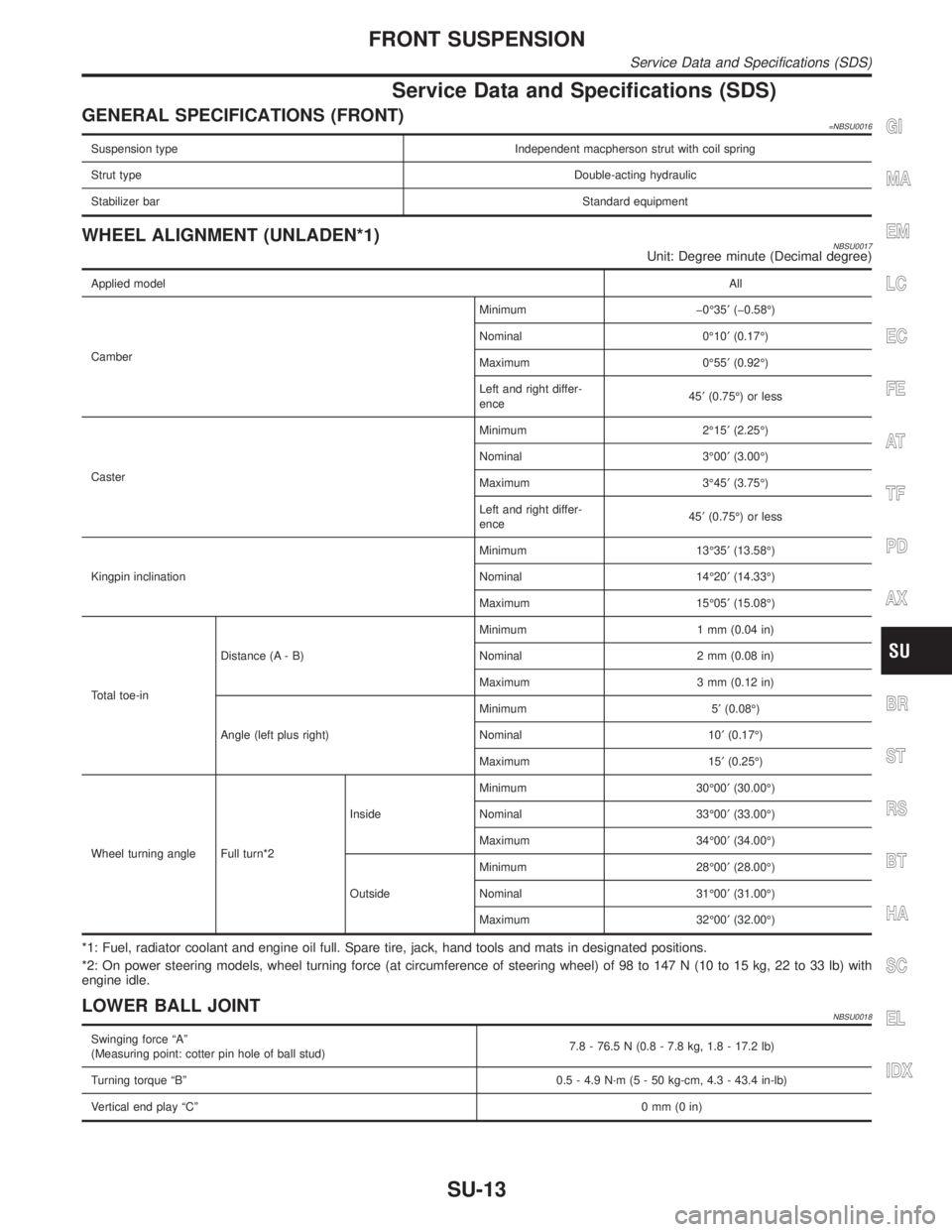
Service Data and Specifications (SDS)
GENERAL SPECIFICATIONS (FRONT)=NBSU0016
Suspension type Independent macpherson strut with coil spring
Strut typeDouble-acting hydraulic
Stabilizer barStandard equipment
WHEEL ALIGNMENT (UNLADEN*1)NBSU0017Unit: Degree minute (Decimal degree)
Applied modelAll
CamberMinimum þ0É35¢(þ0.58É)
Nominal 0É10¢(0.17É)
Maximum 0É55¢(0.92É)
Left and right differ-
ence45¢(0.75É) or less
CasterMinimum 2É15¢(2.25É)
Nominal 3É00¢(3.00É)
Maximum 3É45¢(3.75É)
Left and right differ-
ence45¢(0.75É) or less
Kingpin inclinationMinimum 13É35¢(13.58É)
Nominal 14É20¢(14.33É)
Maximum 15É05¢(15.08É)
Total toe-inDistance (A - B)Minimum 1 mm (0.04 in)
Nominal 2 mm (0.08 in)
Maximum 3 mm (0.12 in)
Angle (left plus right)Minimum 5¢(0.08É)
Nominal 10¢(0.17É)
Maximum 15¢(0.25É)
Wheel turning angle Full turn*2InsideMinimum 30É00¢(30.00É)
Nominal 33É00¢(33.00É)
Maximum 34É00¢(34.00É)
OutsideMinimum 28É00¢(28.00É)
Nominal 31É00¢(31.00É)
Maximum 32É00¢(32.00É)
*1: Fuel, radiator coolant and engine oil full. Spare tire, jack, hand tools and mats in designated positions.
*2: On power steering models, wheel turning force (at circumference of steering wheel) of 98 to 147 N (10 to 15 kg, 22 to 33 lb) with
engine idle.
LOWER BALL JOINTNBSU0018
Swinging force ªAº
(Measuring point: cotter pin hole of ball stud)7.8 - 76.5 N (0.8 - 7.8 kg, 1.8 - 17.2 lb)
Turning torque ªBº 0.5 - 4.9 N´m (5 - 50 kg-cm, 4.3 - 43.4 in-lb)
Vertical end play ªCº0mm(0in)
GI
MA
EM
LC
EC
FE
AT
TF
PD
AX
BR
ST
RS
BT
HA
SC
EL
IDX
FRONT SUSPENSION
Service Data and Specifications (SDS)
SU-13
Page 2229 of 2395

WHEELARCH HEIGHT (UNLADEN*)NBSU0019Unit: mm (in)
SFA746B
Applied model 245/70 R16 tire 245/65 R17 tire
Front (Hf)794 (31.26)
Rear (Hr)810 (31.89)
*: Fuel, radiator coolant and engine oil full. Spare tire, jack, hand tools and mats in designated positions.
WHEEL RUNOUT AVERAGE*NBSU0020Unit: mm (in)
Radial runout limit0.3 (0.012)
Lateral runout limit0.3 (0.012)
*: Wheel runout average = (Outside runout value + Inside runout value) x 0.5
FRONT SUSPENSION
Service Data and Specifications (SDS) (Cont'd)
SU-14
Page 2230 of 2395
SBR686C
Precautions
PRECAUTIONSNBSU0021IWhen installing rubber parts, final tightening must be car-
ried out under unladen condition* with tires on ground.
*Fuel, radiator coolant and engine oil full. Spare tire, jack,
hand tools and mats in designated positions.
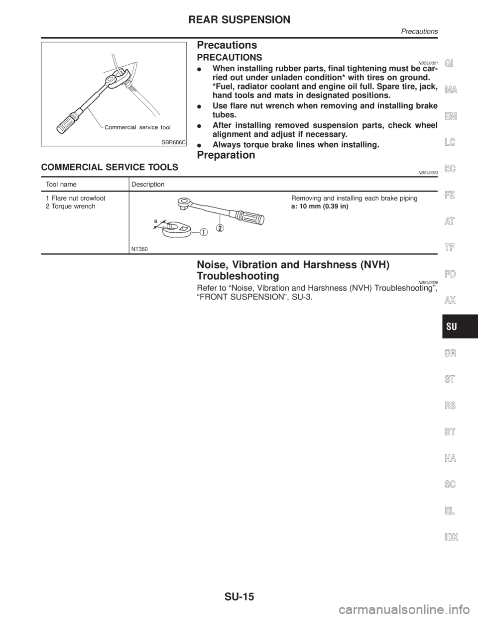
IUse flare nut wrench when removing and installing brake
tubes.
IAfter installing removed suspension parts, check wheel
alignment and adjust if necessary.
IAlways torque brake lines when installing.
Preparation
COMMERCIAL SERVICE TOOLSNBSU0023
Tool name Description
1 Flare nut crowfoot
2 Torque wrench
NT360
Removing and installing each brake piping
a: 10 mm (0.39 in)
Noise, Vibration and Harshness (NVH)
Troubleshooting
NBSU0036Refer to ªNoise, Vibration and Harshness (NVH) Troubleshootingº,
ªFRONT SUSPENSIONº, SU-3.
GI
MA
EM
LC
EC
FE
AT
TF
PD
AX
BR
ST
RS
BT
HA
SC
EL
IDX
REAR SUSPENSION
Precautions
SU-15
Page 2236 of 2395
TRANSFER
SECTION
TF
CONTENTS
PRECAUTIONS...............................................................3
Supplemental Restraint System (SRS)²AIR
BAG²and²SEAT BELT PRE-TENSIONER²...............3
Precautions ..................................................................3
Service Notice..............................................................4
Wiring Diagrams and Trouble Diagnosis .....................4
PREPARATION...............................................................5
Special Service Tools ..................................................5
Commercial Service Tools ...........................................9
ALL-MODE 4WD SYSTEM...........................................10
Cross-sectional View .................................................10
Control System .......................................................... 11
ALL-MODE 4WD TRANSFER BASIC CONTROL........12
HYDRAULIC CONTROL CIRCUITS...........................12
OUTLINE................................................................12
CONTROL SYSTEM DIAGRAM................................13
INDICATIONS OF 4WD WARNING LAMP..................13
Location of Electrical Parts ........................................14
Description of Electrical Parts ...................................15
TRANSFER MOTOR................................................15
WAIT DETECTION SWITCH.....................................15
2-4WD SHIFT SOLENOID VALVE.............................16
LINE PRESSURE SWITCH.......................................16
Circuit Diagram for Quick Pinpoint Check.................17
Wiring Diagram - TF -................................................18
ON BOARD DIAGNOSTIC SYSTEM
DESCRIPTION...............................................................27
Trouble Diagnosis without CONSULT-II ....................27
DESCRIPTION........................................................27
SELF-DIAGNOSTIC PROCEDURE............................28
INDICATIONS OF 4WD WARNING LAMP..................29
Trouble Diagnosis with CONSULT-II .........................30
SELF-DIAGNOSIS...................................................30
SELF-DIAGNOSTIC ITEMS......................................31
DATA MONITOR......................................................33
DATA MONITOR ITEMS...........................................34
REFERENCE VALUE IN DATA MONITOR MODE......36
WORK SUPPORT....................................................38
CLUTCH FORCE RELEASE LIMIT ADJUSTMENT.....39
TROUBLE DIAGNOSIS - INTRODUCTION..................41Introduction ................................................................41
DESCRIPTION........................................................41
DIAGNOSTIC WORKSHEET.....................................41
Work Flow ..................................................................43
HOW TO PERFORM TROUBLE DIAGNOSES FOR
QUICK AND ACCURATE REPAIR
.............................43
TROUBLE DIAGNOSIS - BASIC INSPECTION...........44
Listen to Customer Complaints .................................44
Transfer Fluid Check .................................................44
Road Test...................................................................44
PREPARATION FOR ROAD TEST............................44
1. CHECK BEFORE ENGINE IS STARTED...............45
2. CHECK AT IDLE..................................................47
3. CRUISE TEST.....................................................51
TROUBLE DIAGNOSIS - GENERAL
DESCRIPTION...............................................................54
Transfer Control Unit Terminals and Reference
Value ..........................................................................54
REMOVAL AND INSTALLATION OF TRANSFER
CONTROL UNIT
......................................................54
INSPECTION OF TRANSFER CONTROL UNIT..........54
TRANSFER CONTROL UNIT INSPECTION TABLE....55
VEHICLE SPEED SENSOR (FRONT
REVOLUTION SENSOR)..............................................61
Diagnostic Procedure ................................................61
4WD SOLENOID VALVE...............................................64
Diagnostic Procedure ................................................64
2-4WD SHIFT SOLENOID VALVE AND 4WD
SHIFT SWITCH..............................................................66
Diagnostic Procedure ................................................66
TRANSFER MOTOR AND TRANSFER MOTOR
RELAY...........................................................................70
Diagnostic Procedure ................................................70
TRANSFER FLUID TEMPERATURE SENSOR............73
Diagnostic Procedure ................................................73
ATP SWITCH, WAIT DETECTION SWITCH AND
NEUTRAL-4LO SWITCH...............................................76
Diagnostic Procedure ................................................76
CLUTCH PRESSURE SWITCH....................................80
Diagnostic Procedure ................................................80
GI
MA
EM
LC
EC
FE
AT
PD
AX
SU
BR
ST
RS
BT
HA
SC
EL
IDX
Page 2248 of 2395

CONTROL SYSTEM DIAGRAMNBTF0007S04
SMT763D
INDICATIONS OF 4WD WARNING LAMPNBTF0007S05
Condition Content 4WD warning lamp
During self-diagnosis Indicates the malfunction position by number of flickers. Flickers at malfunction mode.
Lamp check*Checks the lamp by turning ON during engine starting. After
engine starts, it turns OFF if there are no malfunctions.ON
Malfunction in 4WD system*Turns ON to indicate malfunction. When ignition switch is
turned to ªOFFº or the malfunction is corrected, it turns OFF.ON
When vehicle is driven with different
diameters of front and rear tiresFlickers once every 2 seconds.
Turns OFF when ignition switch is ªOFFº.Flickers once every 2 sec-
onds.
High fluid temperature in transfer
unitWhen fluid temperature is high or fluid temperature sensor
circuit is shorted, it flickers twice every second.
It turns OFF when fluid temperature becomes normal.Flickers twice a second.
Other than above (System is nor-
mal.)Lamp is OFF. OFF
*: When 4WD warning lamp is ON, all the 4WD shift indicator lamps turn OFF.
GI
MA
EM
LC
EC
FE
AT
PD
AX
SU
BR
ST
RS
BT
HA
SC
EL
IDX
ALL-MODE 4WD SYSTEM
Control System (Cont'd)
TF-13
Page 2262 of 2395
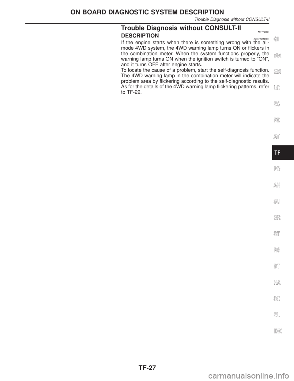
Trouble Diagnosis without CONSULT-IINBTF0011DESCRIPTIONNBTF0011S01If the engine starts when there is something wrong with the all-
mode 4WD system, the 4WD warning lamp turns ON or flickers in
the combination meter. When the system functions properly, the
warning lamp turns ON when the ignition switch is turned to ªONº,
and it turns OFF after engine starts.
To locate the cause of a problem, start the self-diagnosis function.
The 4WD warning lamp in the combination meter will indicate the
problem area by flickering according to the self-diagnostic results.
As for the details of the 4WD warning lamp flickering patterns, refer
to TF-29.GI
MA
EM
LC
EC
FE
AT
PD
AX
SU
BR
ST
RS
BT
HA
SC
EL
IDX
ON BOARD DIAGNOSTIC SYSTEM DESCRIPTION
Trouble Diagnosis without CONSULT-II
TF-27
Page 2264 of 2395
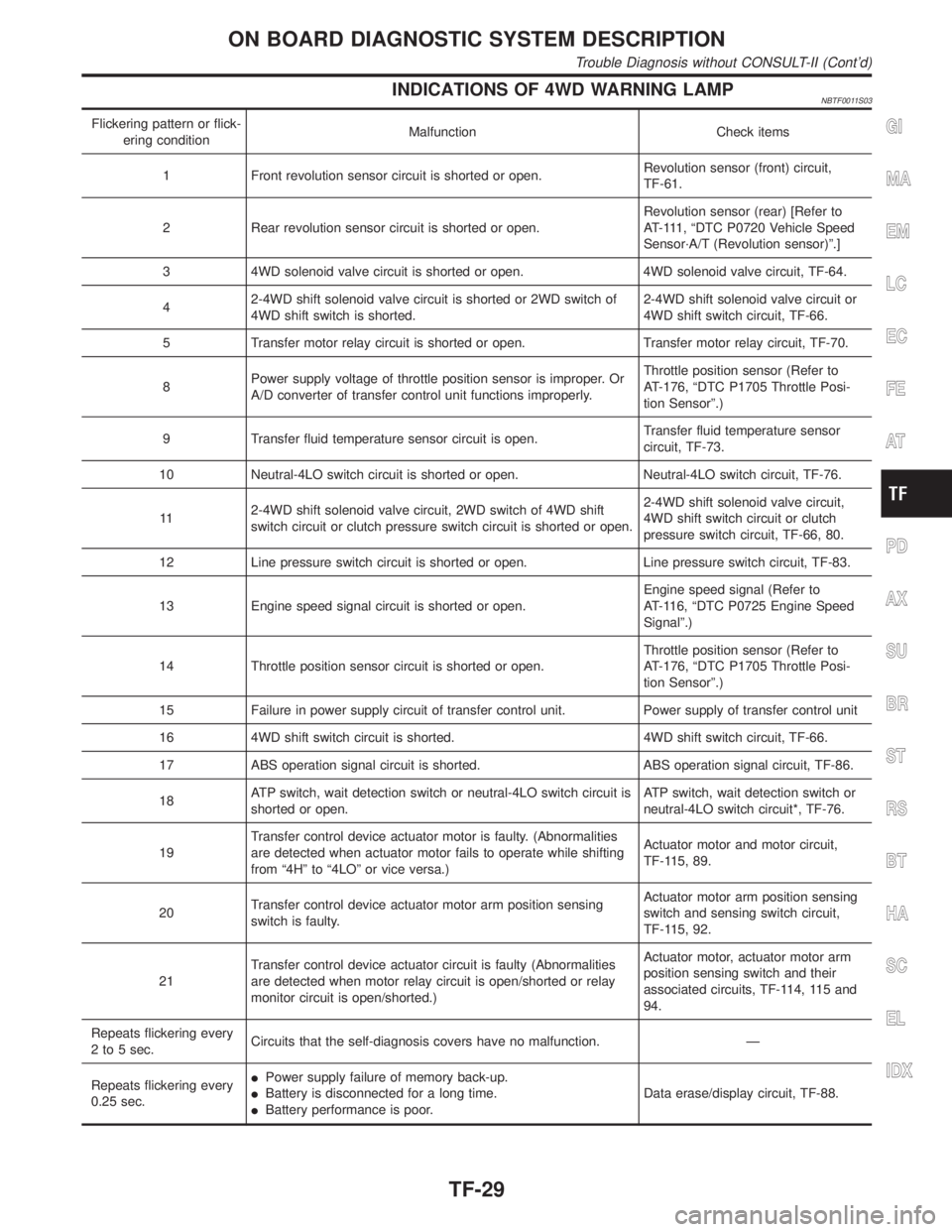
INDICATIONS OF 4WD WARNING LAMPNBTF0011S03
Flickering pattern or flick-
ering conditionMalfunction Check items
1 Front revolution sensor circuit is shorted or open.Revolution sensor (front) circuit,
TF-61.
2 Rear revolution sensor circuit is shorted or open.Revolution sensor (rear) [Refer to
AT-111, ªDTC P0720 Vehicle Speed
Sensor´A/T (Revolution sensor)º.]
3 4WD solenoid valve circuit is shorted or open. 4WD solenoid valve circuit, TF-64.
42-4WD shift solenoid valve circuit is shorted or 2WD switch of
4WD shift switch is shorted.2-4WD shift solenoid valve circuit or
4WD shift switch circuit, TF-66.
5 Transfer motor relay circuit is shorted or open. Transfer motor relay circuit, TF-70.
8Power supply voltage of throttle position sensor is improper. Or
A/D converter of transfer control unit functions improperly.Throttle position sensor (Refer to
AT-176, ªDTC P1705 Throttle Posi-
tion Sensorº.)
9 Transfer fluid temperature sensor circuit is open.Transfer fluid temperature sensor
circuit, TF-73.
10 Neutral-4LO switch circuit is shorted or open. Neutral-4LO switch circuit, TF-76.
112-4WD shift solenoid valve circuit, 2WD switch of 4WD shift
switch circuit or clutch pressure switch circuit is shorted or open.2-4WD shift solenoid valve circuit,
4WD shift switch circuit or clutch
pressure switch circuit, TF-66, 80.
12 Line pressure switch circuit is shorted or open. Line pressure switch circuit, TF-83.
13 Engine speed signal circuit is shorted or open.Engine speed signal (Refer to
AT-116, ªDTC P0725 Engine Speed
Signalº.)
14 Throttle position sensor circuit is shorted or open.Throttle position sensor (Refer to
AT-176, ªDTC P1705 Throttle Posi-
tion Sensorº.)
15 Failure in power supply circuit of transfer control unit. Power supply of transfer control unit
16 4WD shift switch circuit is shorted. 4WD shift switch circuit, TF-66.
17 ABS operation signal circuit is shorted. ABS operation signal circuit, TF-86.
18ATP switch, wait detection switch or neutral-4LO switch circuit is
shorted or open.ATP switch, wait detection switch or
neutral-4LO switch circuit*, TF-76.
19Transfer control device actuator motor is faulty. (Abnormalities
are detected when actuator motor fails to operate while shifting
from ª4Hº to ª4LOº or vice versa.)Actuator motor and motor circuit,
TF-115, 89.
20Transfer control device actuator motor arm position sensing
switch is faulty.Actuator motor arm position sensing
switch and sensing switch circuit,
TF-115, 92.
21Transfer control device actuator circuit is faulty (Abnormalities
are detected when motor relay circuit is open/shorted or relay
monitor circuit is open/shorted.)Actuator motor, actuator motor arm
position sensing switch and their
associated circuits, TF-114, 115 and
94.
Repeats flickering every
2 to 5 sec.Circuits that the self-diagnosis covers have no malfunction. Ð
Repeats flickering every
0.25 sec.IPower supply failure of memory back-up.
IBattery is disconnected for a long time.
IBattery performance is poor.Data erase/display circuit, TF-88.GI
MA
EM
LC
EC
FE
AT
PD
AX
SU
BR
ST
RS
BT
HA
SC
EL
IDX
ON BOARD DIAGNOSTIC SYSTEM DESCRIPTION
Trouble Diagnosis without CONSULT-II (Cont'd)
TF-29