Page 974 of 2395
9 CHECK THROTTLE POSITION SENSOR
1. Start engine and warm it up to normal operating temperature.
2. Stop engine (ignition switch OFF).
3. Remove the vacuum hose connected to the throttle opener.
4. Connect suitable vacuum hose to the vacuum pump and the opener.
5. Apply vacuum [more than þ40.0 kPa (þ300 mmHg, þ11.81 inHg)] until the throttle drum becomes free from the rod of
the throttle opener.
SEF793W
6. Turn ignition switch ON.
7. Check voltage between ECM terminal 91 (Throttle position sensor signal) and ground.
Voltage measurement must be made with throttle position sensor installed in vehicle.
SEF348X
OK or NG
OK©GO TO 10.
NG©Replace throttle position sensor.
10 CHECK INTERMITTENT INCIDENT
Refer to ªTROUBLE DIAGNOSIS FOR INTERMITTENT INCIDENTº, EC-140.
©INSPECTION END
GI
MA
EM
LC
FE
AT
TF
PD
AX
SU
BR
ST
RS
BT
HA
SC
EL
IDX
DTC P0510 CLOSED THROTTLE POSITION SWITCH
Diagnostic Procedure (Cont'd)
EC-439
Page 996 of 2395

SEF174Y
PROCEDURE FOR MALFUNCTION BNBEC0528S02TESTING CONDITION:
IFor best results, perform the test at a temperature above
5ÉC (41ÉF).
IBefore performing the following procedure, confirm that
battery voltage is more than 10V at idle, then stop engine
immediately.
With CONSULT-IINBEC0528S02011) Turn ignition switch ªOFFº and wait at least 10 seconds.
2) Turn ignition switch ªONº.
3) Check ªCOOLAN TEMP/Sº in ªDATA MONITORº mode with
CONSULT-II.
4) Confirm COOLAN TEMP/S value is 40ÉC (104ÉF) or less.
If the value is more than 40ÉC (104ÉF), park the vehicle in a
cool place and retry from step 1.
5) Start engine and wait until COOLAN TEMP/S value increases
to more than 55ÉC (131ÉF).
If 1st trip DTC is detected, go to ªDiagnostic Procedureº,
EC-463.
With GSTNBEC0528S0202Follow the procedure ªWith CONSULT-IIº above.
SEF174Y
PROCEDURE FOR MALFUNCTION CNBEC0528S03TESTING CONDITION:
IFor best results, perform the test at a temperature above
5ÉC (41ÉF).
IBefore performing the following procedure, confirm that
battery voltage is more than 10V at idle.
With CONSULT-IINBEC0528S03011) Start engine and warm it up to normal operating temperature.
2) Turn ignition switch ªOFFº and wait at least 10 seconds.
3) Turn ignition switch ªONº again and select ªDATA MONITORº
mode with CONSULT-II.
4) Start engine and let it idle for at least 20 seconds. If 1st trip
DTC is detected, go to ªDiagnostic Procedureº, EC-463.
With GSTNBEC0528S0302Follow the procedure ªWith CONSULT-IIº above.
GI
MA
EM
LC
FE
AT
TF
PD
AX
SU
BR
ST
RS
BT
HA
SC
EL
IDX
DTC P1130 SWIRL CONTROL VALVE CONTROL SOLENOID VALVE
DTC Confirmation Procedure (Cont'd)
EC-461
Page 1007 of 2395
11 CHECK THROTTLE POSITION SENSOR
With CONSULT-II
1. Start engine and warm it up to normal operating temperature.
2. Stop engine (ignition switch OFF).
3. Remove the vacuum hose connected to the throttle opener.
4. Connect suitable vacuum hose to the vacuum pump and the opener.
5. Apply vacuum [more than þ40.0 kPa (þ300 mmHg, þ11.81 inHg)] until the throttle drum becomes free from the rod of
the throttle opener.
SEF793W
6. Turn ignition switch ON.
7. Select ªDATA MONITORº mode with CONSULT-II.
8. Check voltage of ªTHRTL POS SENº under the following conditions.
Voltage measurement must be made with throttle position sensor installed in vehicle.
SEF062Y
OK or NG
OK©GO TO 14.
NG©GO TO 13.
DTC P1130 SWIRL CONTROL VALVE CONTROL SOLENOID VALVE
Diagnostic Procedure (Cont'd)
EC-472
Page 1008 of 2395

12 CHECK THROTTLE POSITION SENSOR
Without CONSULT-II
1. Start engine and warm it up to normal operating temperature.
2. Stop engine (ignition switch OFF).
3. Remove the vacuum hose connected to the throttle opener.
4. Connect suitable vacuum hose to the vacuum pump and the opener.
5. Apply vacuum [more than þ40.0 kPa (þ300 mmHg, þ11.81 inHg)] until the throttle drum becomes free from the rod of
the throttle opener.
SEF793W
6. Turn ignition switch ON.
7. Check voltage between ECM terminal 91 (Throttle position sensor signal) and ground.
Voltage measurement must be made with throttle position sensor installed in vehicle.
MTBL0231
OK or NG
OK©GO TO 14.
NG©GO TO 13.
13 ADJUST CLOSED THROTTLE POSITION SWITCH
Adjust closed throttle position switch. Refer to ªBasic Inspectionº, EC-101.
MTBL0655
OK or NG
OK©GO TO 14.
NG©Replace throttle position sensor. To adjust it, perform ªBasic Inspectionº, EC-101.
GI
MA
EM
LC
FE
AT
TF
PD
AX
SU
BR
ST
RS
BT
HA
SC
EL
IDX
DTC P1130 SWIRL CONTROL VALVE CONTROL SOLENOID VALVE
Diagnostic Procedure (Cont'd)
EC-473
Page 1015 of 2395
11 CHECK THROTTLE POSITION SENSOR
With CONSULT-II
1. Start engine and warm it up to normal operating temperature.
2. Stop engine (ignition switch OFF).
3. Remove the vacuum hose connected to the throttle opener.
4. Connect suitable vacuum hose to the vacuum pump and the opener.
5. Apply vacuum [more than þ40.0 kPa (þ300 mmHg, þ11.81 inHg)] until the throttle drum becomes free from the rod of
the throttle opener.
SEF793W
6. Turn ignition switch ON.
7. Select ªDATA MONITORº mode with CONSULT-II.
8. Check voltage of ªTHRTL POS SENº under the following conditions.
Voltage measurement must be made with throttle position sensor installed in vehicle.
SEF062Y
OK or NG
OK©GO TO 14.
NG©GO TO 13.
DTC P1130 SWIRL CONTROL VALVE CONTROL SOLENOID VALVE
Diagnostic Procedure (Cont'd)
EC-480
Page 1016 of 2395

12 CHECK THROTTLE POSITION SENSOR
Without CONSULT-II
1. Start engine and warm it up to normal operating temperature.
2. Stop engine (ignition switch OFF).
3. Remove the vacuum hose connected to the throttle opener.
4. Connect suitable vacuum hose to the vacuum pump and the opener.
5. Apply vacuum [more than þ40.0 kPa (þ300 mmHg, þ11.81 inHg)] until the throttle drum becomes free from the rod of
the throttle opener.
SEF793W
6. Turn ignition switch ON.
7. Check voltage between ECM terminal 91 (Throttle position sensor signal) and ground.
Voltage measurement must be made with throttle position sensor installed in vehicle.
MTBL0231
OK or NG
OK©GO TO 14.
NG©GO TO 13.
13 ADJUST CLOSED THROTTLE POSITION SWITCH
Adjust closed throttle position switch. Refer to ªBasic Inspectionº, EC-101.
MTBL0655
OK or NG
OK©GO TO 14.
NG©Replace throttle position sensor. To adjust it, perform ªBasic Inspectionº, EC-101.
14 CHECK INTERMITTENT INCIDENT
Perform ªTROUBLE DIAGNOSIS FOR INTERMITTENT INCIDENTº, EC-140.
©INSPECTION END
GI
MA
EM
LC
FE
AT
TF
PD
AX
SU
BR
ST
RS
BT
HA
SC
EL
IDX
DTC P1130 SWIRL CONTROL VALVE CONTROL SOLENOID VALVE
Diagnostic Procedure (Cont'd)
EC-481
Page 1070 of 2395

11 CHECK EVAP CANISTER
Weigh the EVAP canister with the EVAP canister vent control valve attached.
The weight should be less than 1.8 kg (4.0 lb).
OK or NG
OK (With CONSULT-II)©GO TO 13.
OK (Without CONSULT-
II)©GO TO 14.
NG©GO TO 12.
12 DETECT MALFUNCTIONING PART
Check the following.
IEVAP canister for damage
IEVAP hose between EVAP canister and water separator for clogging or poor connection
©Repair hose or replace EVAP canister.
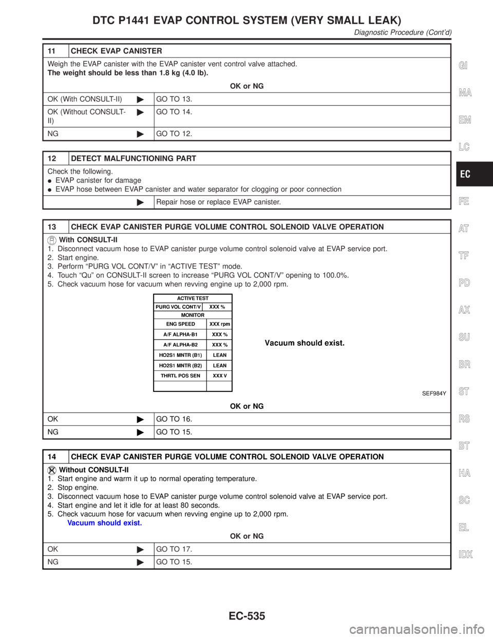
13 CHECK EVAP CANISTER PURGE VOLUME CONTROL SOLENOID VALVE OPERATION
With CONSULT-II
1. Disconnect vacuum hose to EVAP canister purge volume control solenoid valve at EVAP service port.
2. Start engine.
3. Perform ªPURG VOL CONT/Vº in ªACTIVE TESTº mode.
4. Touch ªQuº on CONSULT-II screen to increase ªPURG VOL CONT/Vº opening to 100.0%.
5. Check vacuum hose for vacuum when revving engine up to 2,000 rpm.
SEF984Y
OK or NG
OK©GO TO 16.
NG©GO TO 15.
14 CHECK EVAP CANISTER PURGE VOLUME CONTROL SOLENOID VALVE OPERATION
Without CONSULT-II
1. Start engine and warm it up to normal operating temperature.
2. Stop engine.
3. Disconnect vacuum hose to EVAP canister purge volume control solenoid valve at EVAP service port.
4. Start engine and let it idle for at least 80 seconds.
5. Check vacuum hose for vacuum when revving engine up to 2,000 rpm.
Vacuum should exist.
OK or NG
OK©GO TO 17.
NG©GO TO 15.
GI
MA
EM
LC
FE
AT
TF
PD
AX
SU
BR
ST
RS
BT
HA
SC
EL
IDX
DTC P1441 EVAP CONTROL SYSTEM (VERY SMALL LEAK)
Diagnostic Procedure (Cont'd)
EC-535
Page 1076 of 2395

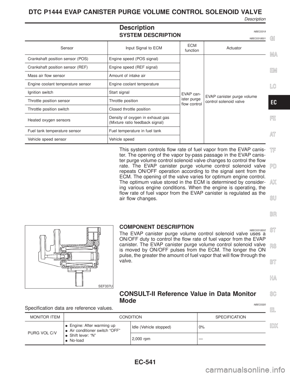
DescriptionNBEC0319SYSTEM DESCRIPTIONNBEC0319S01
Sensor Input Signal to ECMECM
functionActuator
Crankshaft position sensor (POS) Engine speed (POS signal)
EVAP can-
ister purge
flow controlEVAP canister purge volume
control solenoid valve Crankshaft position sensor (REF) Engine speed (REF signal)
Mass air flow sensor Amount of intake air
Engine coolant temperature sensor Engine coolant temperature
Ignition switch Start signal
Throttle position sensor Throttle position
Throttle position switch Closed throttle position
Heated oxygen sensorsDensity of oxygen in exhaust gas
(Mixture ratio feedback signal)
Fuel tank temperature sensor Fuel temperature in fuel tank
Vehicle speed sensor Vehicle speed
This system controls flow rate of fuel vapor from the EVAP canis-
ter. The opening of the vapor by-pass passage in the EVAP canis-
ter purge volume control solenoid valve changes to control the flow
rate. The EVAP canister purge volume control solenoid valve
repeats ON/OFF operation according to the signal sent from the
ECM. The opening of the valve varies for optimum engine control.
The optimum value stored in the ECM is determined by consider-
ing various engine conditions. When the engine is operating, the
flow rate of fuel vapor from the EVAP canister is regulated as the
air flow changes.
SEF337U
COMPONENT DESCRIPTIONNBEC0319S02The EVAP canister purge volume control solenoid valve uses a
ON/OFF duty to control the flow rate of fuel vapor from the EVAP
canister. The EVAP canister purge volume control solenoid valve
is moved by ON/OFF pulses from the ECM. The longer the ON
pulse, the greater the amount of fuel vapor that will flow through the
valve.
CONSULT-II Reference Value in Data Monitor
Mode
NBEC0320Specification data are reference values.
MONITOR ITEM CONDITION SPECIFICATION
PURG VOL C/VIEngine: After warming up
IAir conditioner switch ªOFFº
IShift lever: ªNº
INo-loadIdle (Vehicle stopped) 0%
2,000 rpm Ð
GI
MA
EM
LC
FE
AT
TF
PD
AX
SU
BR
ST
RS
BT
HA
SC
EL
IDX
DTC P1444 EVAP CANISTER PURGE VOLUME CONTROL SOLENOID VALVE
Description
EC-541