2001 INFINITI QX4 revolution sensor
[x] Cancel search: revolution sensorPage 2237 of 2395
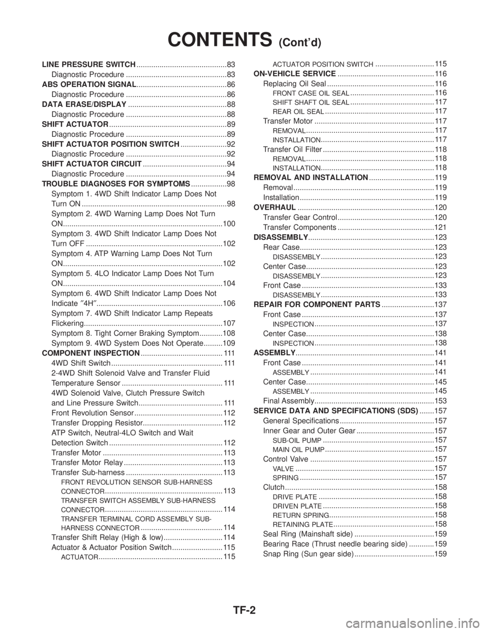
LINE PRESSURE SWITCH...........................................83
Diagnostic Procedure ................................................83
ABS OPERATION SIGNAL...........................................86
Diagnostic Procedure ................................................86
DATA ERASE/DISPLAY...............................................88
Diagnostic Procedure ................................................88
SHIFT ACTUATOR........................................................89
Diagnostic Procedure ................................................89
SHIFT ACTUATOR POSITION SWITCH......................92
Diagnostic Procedure ................................................92
SHIFT ACTUATOR CIRCUIT........................................94
Diagnostic Procedure ................................................94
TROUBLE DIAGNOSES FOR SYMPTOMS.................98
Symptom 1. 4WD Shift Indicator Lamp Does Not
Turn ON .....................................................................98
Symptom 2. 4WD Warning Lamp Does Not Turn
ON............................................................................100
Symptom 3. 4WD Shift Indicator Lamp Does Not
Turn OFF .................................................................102
Symptom 4. ATP Warning Lamp Does Not Turn
ON............................................................................102
Symptom 5. 4LO Indicator Lamp Does Not Turn
ON............................................................................104
Symptom 6. 4WD Shift Indicator Lamp Does Not
Indicate²4H²............................................................106
Symptom 7. 4WD Shift Indicator Lamp Repeats
Flickering..................................................................107
Symptom 8. Tight Corner Braking Symptom...........108
Symptom 9. 4WD System Does Not Operate.........109
COMPONENT INSPECTION....................................... 111
4WD Shift Switch ..................................................... 111
2-4WD Shift Solenoid Valve and Transfer Fluid
Temperature Sensor ................................................ 111
4WD Solenoid Valve, Clutch Pressure Switch
and Line Pressure Switch........................................ 111
Front Revolution Sensor .......................................... 112
Transfer Dropping Resistor...................................... 112
ATP Switch, Neutral-4LO Switch and Wait
Detection Switch ...................................................... 112
Transfer Motor ......................................................... 113
Transfer Motor Relay ............................................... 113
Transfer Sub-harness .............................................. 113
FRONT REVOLUTION SENSOR SUB-HARNESS
CONNECTOR
........................................................ 113
TRANSFER SWITCH ASSEMBLY SUB-HARNESS
CONNECTOR
........................................................ 114
TRANSFER TERMINAL CORD ASSEMBLY SUB-
HARNESS CONNECTOR
....................................... 114
Transfer Shift Relay (High & low) ............................ 114
Actuator & Actuator Position Switch ........................ 115
ACTUATOR........................................................... 115
ACTUATOR POSITION SWITCH............................ 115
ON-VEHICLE SERVICE.............................................. 116
Replacing Oil Seal ................................................... 116
FRONT CASE OIL SEAL........................................ 116
SHIFT SHAFT OIL SEAL........................................ 117
REAR OIL SEAL.................................................... 117
Transfer Motor ......................................................... 117
REMOVAL............................................................. 117
INSTALLATION...................................................... 117
Transfer Oil Filter ..................................................... 118
REMOVAL............................................................. 118
INSTALLATION...................................................... 118
REMOVAL AND INSTALLATION............................... 119
Removal ................................................................... 119
Installation ................................................................ 119
OVERHAUL.................................................................120
Transfer Gear Control ..............................................120
Transfer Components ..............................................121
DISASSEMBLY............................................................123
Rear Case................................................................123
DISASSEMBLY......................................................123
Center Case.............................................................123
DISASSEMBLY......................................................123
Front Case ...............................................................133
DISASSEMBLY......................................................133
REPAIR FOR COMPONENT PARTS.........................137
Front Case ...............................................................137
INSPECTION.........................................................137
Center Case.............................................................138
INSPECTION.........................................................138
ASSEMBLY..................................................................141
Front Case ...............................................................141
ASSEMBLY...........................................................141
Center Case.............................................................145
ASSEMBLY...........................................................145
Final Assembly.........................................................153
SERVICE DATA AND SPECIFICATIONS (SDS).......157
General Specifications .............................................157
Inner Gear and Outer Gear .....................................157
SUB-OIL PUMP.....................................................157
MAIN OIL PUMP....................................................157
Control Valve ...........................................................157
VALVE..................................................................157
SPRING................................................................157
Clutch .......................................................................158
DRIVE PLATE.......................................................158
DRIVEN PLATE.....................................................158
RETURN SPRING..................................................158
RETAINING PLATE................................................158
Seal Ring (Mainshaft side) ......................................159
Bearing Race (Thrust needle bearing side) ............159
Snap Ring (Sun gear side) ......................................159
CONTENTS(Cont'd)
TF-2
Page 2264 of 2395
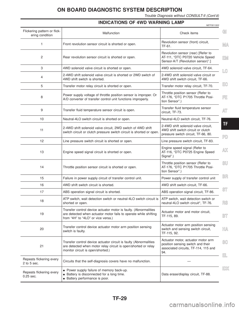
INDICATIONS OF 4WD WARNING LAMPNBTF0011S03
Flickering pattern or flick-
ering conditionMalfunction Check items
1 Front revolution sensor circuit is shorted or open.Revolution sensor (front) circuit,
TF-61.
2 Rear revolution sensor circuit is shorted or open.Revolution sensor (rear) [Refer to
AT-111, ªDTC P0720 Vehicle Speed
Sensor´A/T (Revolution sensor)º.]
3 4WD solenoid valve circuit is shorted or open. 4WD solenoid valve circuit, TF-64.
42-4WD shift solenoid valve circuit is shorted or 2WD switch of
4WD shift switch is shorted.2-4WD shift solenoid valve circuit or
4WD shift switch circuit, TF-66.
5 Transfer motor relay circuit is shorted or open. Transfer motor relay circuit, TF-70.
8Power supply voltage of throttle position sensor is improper. Or
A/D converter of transfer control unit functions improperly.Throttle position sensor (Refer to
AT-176, ªDTC P1705 Throttle Posi-
tion Sensorº.)
9 Transfer fluid temperature sensor circuit is open.Transfer fluid temperature sensor
circuit, TF-73.
10 Neutral-4LO switch circuit is shorted or open. Neutral-4LO switch circuit, TF-76.
112-4WD shift solenoid valve circuit, 2WD switch of 4WD shift
switch circuit or clutch pressure switch circuit is shorted or open.2-4WD shift solenoid valve circuit,
4WD shift switch circuit or clutch
pressure switch circuit, TF-66, 80.
12 Line pressure switch circuit is shorted or open. Line pressure switch circuit, TF-83.
13 Engine speed signal circuit is shorted or open.Engine speed signal (Refer to
AT-116, ªDTC P0725 Engine Speed
Signalº.)
14 Throttle position sensor circuit is shorted or open.Throttle position sensor (Refer to
AT-176, ªDTC P1705 Throttle Posi-
tion Sensorº.)
15 Failure in power supply circuit of transfer control unit. Power supply of transfer control unit
16 4WD shift switch circuit is shorted. 4WD shift switch circuit, TF-66.
17 ABS operation signal circuit is shorted. ABS operation signal circuit, TF-86.
18ATP switch, wait detection switch or neutral-4LO switch circuit is
shorted or open.ATP switch, wait detection switch or
neutral-4LO switch circuit*, TF-76.
19Transfer control device actuator motor is faulty. (Abnormalities
are detected when actuator motor fails to operate while shifting
from ª4Hº to ª4LOº or vice versa.)Actuator motor and motor circuit,
TF-115, 89.
20Transfer control device actuator motor arm position sensing
switch is faulty.Actuator motor arm position sensing
switch and sensing switch circuit,
TF-115, 92.
21Transfer control device actuator circuit is faulty (Abnormalities
are detected when motor relay circuit is open/shorted or relay
monitor circuit is open/shorted.)Actuator motor, actuator motor arm
position sensing switch and their
associated circuits, TF-114, 115 and
94.
Repeats flickering every
2 to 5 sec.Circuits that the self-diagnosis covers have no malfunction. Ð
Repeats flickering every
0.25 sec.IPower supply failure of memory back-up.
IBattery is disconnected for a long time.
IBattery performance is poor.Data erase/display circuit, TF-88.GI
MA
EM
LC
EC
FE
AT
PD
AX
SU
BR
ST
RS
BT
HA
SC
EL
IDX
ON BOARD DIAGNOSTIC SYSTEM DESCRIPTION
Trouble Diagnosis without CONSULT-II (Cont'd)
TF-29
Page 2265 of 2395
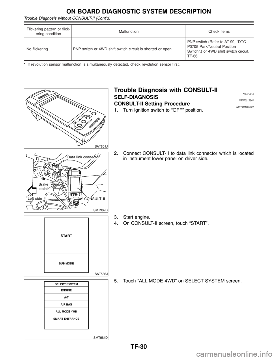
Flickering pattern or flick-
ering conditionMalfunction Check items
No flickering PNP switch or 4WD shift switch circuit is shorted or open.PNP switch (Refer to AT-99, ªDTC
P0705 Park/Neutral Position
Switchº.) or 4WD shift switch circuit,
TF-66.
*: If revolution sensor malfunction is simultaneously detected, check revolution sensor first.
SAT601J
Trouble Diagnosis with CONSULT-IINBTF0012SELF-DIAGNOSISNBTF0012S01CONSULT-II Setting ProcedureNBTF0012S01011. Turn ignition switch to ªOFFº position.
SMT962D
2. Connect CONSULT-II to data link connector which is located
in instrument lower panel on driver side.
SAT586J
3. Start engine.
4. On CONSULT-II screen, touch ªSTARTº.
SMT964D
5. Touch ªALL MODE 4WDº on SELECT SYSTEM screen.
ON BOARD DIAGNOSTIC SYSTEM DESCRIPTION
Trouble Diagnosis without CONSULT-II (Cont'd)
TF-30
Page 2266 of 2395

SMT965D
6. Touch ªSELF-DIAG RESULTSº on SELECT DIAG MODE
screen.
SMT966D
7. Self-diagnostic results are displayed.
SELF-DIAGNOSTIC ITEMSNBTF0012S02
Detected items
(Screen terms for CONSULT-II,
ªSELF-DIAG RESULTº mode)Malfunction is detected when... Check items
Revolution sensor (front) (Note 3)
(VHCL SPEED SEN´FR)IFront revolution sensor (installed on T/F) signal is not
input due to open circuit.
IImproper signal is input while driving.Revolution sensor (front) circuit,
TF-61.
Revolution sensor (rear)
(VHCL SPEED SEN´RR)ISignal from vehicle speed sensor 1 (installed on A/T)
is not input due to open circuit.
IImproper signal is input while driving.Revolution sensor (rear) [Refer to
AT-111, ªDTC P0720 Vehicle Speed
Sensor´A/T (Revolution sensor)º.]
4WD solenoid valve
(DUTY SOLENOID)
IProper voltage is not applied to solenoid valve due to
open or short circuit.4WD solenoid valve, TF-64.
2-4WD shift solenoid valve
(2-4WD SOLENOID)2-4WD shift solenoid valve or
4WD shift switch circuit, TF-66.
Transfer motor relay
(MOTOR RELAY)IMotor does not operate properly due to open or short
circuit in transfer motor or motor relay.Transfer motor relay circuit,
TF-70.
Transfer fluid temperature sensor
(FLUID TEMP SENSOR)ISignal voltage from fluid temperature sensor is abnor-
mally high (T/F fluid temperature is abnormally low)
while driving.Transfer fluid temperature sensor
circuit, TF-73.
Neutral-4LO switch
(N POSI SW TF)IImproper signal is input while driving. Neutral-4LO switch, TF-76.
Clutch pressure
(CLUTCH PRESSURE)IImproper signal is input due to open or short circuit.
IMalfunction occurs in clutch pressure hydraulic circuit.Clutch pressure switch circuit
(*1), TF-80.
Line pressure
(LINE PRESSURE)IImproper signal is input due to open or short circuit.
IMalfunction occurs in line pressure hydraulic circuit.Line pressure switch circuit (*1),
TF-83.
Engine speed signal (Note 1)
(ENGINE SPEED SIG)IEngine speed is abnormally low while driving.Engine speed signal (Refer to
AT-116, ªDTC P0725 Engine Speed
Signalº.)
GI
MA
EM
LC
EC
FE
AT
PD
AX
SU
BR
ST
RS
BT
HA
SC
EL
IDX
ON BOARD DIAGNOSTIC SYSTEM DESCRIPTION
Trouble Diagnosis with CONSULT-II (Cont'd)
TF-31
Page 2267 of 2395
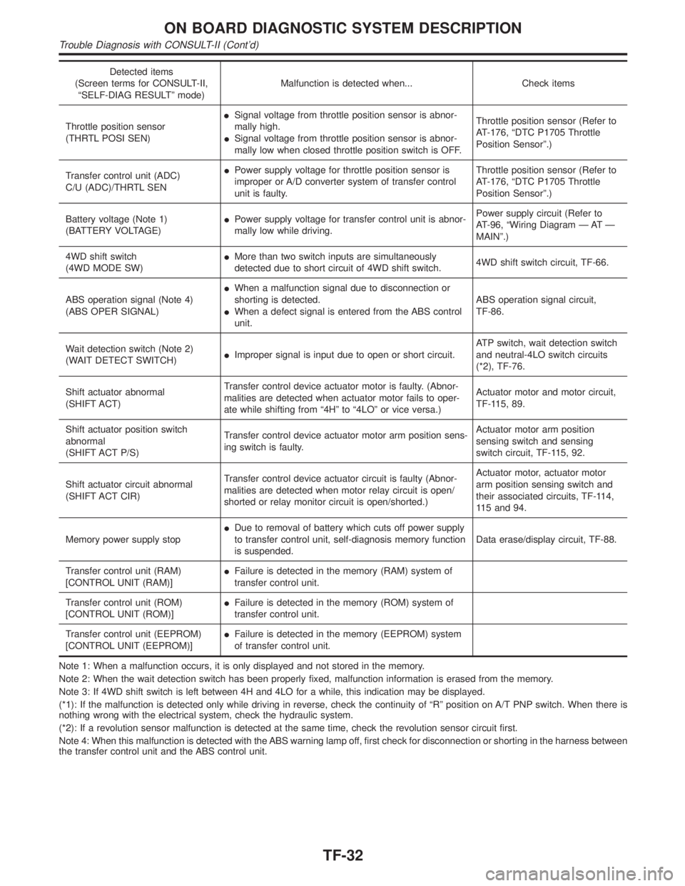
Detected items
(Screen terms for CONSULT-II,
ªSELF-DIAG RESULTº mode)Malfunction is detected when... Check items
Throttle position sensor
(THRTL POSI SEN)ISignal voltage from throttle position sensor is abnor-
mally high.
ISignal voltage from throttle position sensor is abnor-
mally low when closed throttle position switch is OFF.Throttle position sensor (Refer to
AT-176, ªDTC P1705 Throttle
Position Sensorº.)
Transfer control unit (ADC)
C/U (ADC)/THRTL SENIPower supply voltage for throttle position sensor is
improper or A/D converter system of transfer control
unit is faulty.Throttle position sensor (Refer to
AT-176, ªDTC P1705 Throttle
Position Sensorº.)
Battery voltage (Note 1)
(BATTERY VOLTAGE)IPower supply voltage for transfer control unit is abnor-
mally low while driving.Power supply circuit (Refer to
AT-96, ªWiring Diagram Ð AT Ð
MAINº.)
4WD shift switch
(4WD MODE SW)IMore than two switch inputs are simultaneously
detected due to short circuit of 4WD shift switch.4WD shift switch circuit, TF-66.
ABS operation signal (Note 4)
(ABS OPER SIGNAL)IWhen a malfunction signal due to disconnection or
shorting is detected.
IWhen a defect signal is entered from the ABS control
unit.ABS operation signal circuit,
TF-86.
Wait detection switch (Note 2)
(WAIT DETECT SWITCH)IImproper signal is input due to open or short circuit.ATP switch, wait detection switch
and neutral-4LO switch circuits
(*2), TF-76.
Shift actuator abnormal
(SHIFT ACT)Transfer control device actuator motor is faulty. (Abnor-
malities are detected when actuator motor fails to oper-
ate while shifting from ª4Hº to ª4LOº or vice versa.)Actuator motor and motor circuit,
TF-115, 89.
Shift actuator position switch
abnormal
(SHIFT ACT P/S)Transfer control device actuator motor arm position sens-
ing switch is faulty.Actuator motor arm position
sensing switch and sensing
switch circuit, TF-115, 92.
Shift actuator circuit abnormal
(SHIFT ACT CIR)Transfer control device actuator circuit is faulty (Abnor-
malities are detected when motor relay circuit is open/
shorted or relay monitor circuit is open/shorted.)Actuator motor, actuator motor
arm position sensing switch and
their associated circuits, TF-114,
115 and 94.
Memory power supply stopIDue to removal of battery which cuts off power supply
to transfer control unit, self-diagnosis memory function
is suspended.Data erase/display circuit, TF-88.
Transfer control unit (RAM)
[CONTROL UNIT (RAM)]IFailure is detected in the memory (RAM) system of
transfer control unit.
Transfer control unit (ROM)
[CONTROL UNIT (ROM)]IFailure is detected in the memory (ROM) system of
transfer control unit.
Transfer control unit (EEPROM)
[CONTROL UNIT (EEPROM)]IFailure is detected in the memory (EEPROM) system
of transfer control unit.
Note 1: When a malfunction occurs, it is only displayed and not stored in the memory.
Note 2: When the wait detection switch has been properly fixed, malfunction information is erased from the memory.
Note 3: If 4WD shift switch is left between 4H and 4LO for a while, this indication may be displayed.
(*1): If the malfunction is detected only while driving in reverse, check the continuity of ªRº position on A/T PNP switch. When there is
nothing wrong with the electrical system, check the hydraulic system.
(*2): If a revolution sensor malfunction is detected at the same time, check the revolution sensor circuit first.
Note 4: When this malfunction is detected with the ABS warning lamp off, first check for disconnection or shorting in the harness between
the transfer control unit and the ABS control unit.
ON BOARD DIAGNOSTIC SYSTEM DESCRIPTION
Trouble Diagnosis with CONSULT-II (Cont'd)
TF-32
Page 2269 of 2395
![INFINITI QX4 2001 Factory Service Manual SMT963D
12. Monitored data are displayed.
DATA MONITOR ITEMSNBTF0012S04q: StandardH: Option
Item [Unit]Monitor item
Remarks
ECU input
signalsMain sig-
nalsItem menu
selection
Revolution sensor-front [ INFINITI QX4 2001 Factory Service Manual SMT963D
12. Monitored data are displayed.
DATA MONITOR ITEMSNBTF0012S04q: StandardH: Option
Item [Unit]Monitor item
Remarks
ECU input
signalsMain sig-
nalsItem menu
selection
Revolution sensor-front [](/manual-img/42/57027/w960_57027-2268.png)
SMT963D
12. Monitored data are displayed.
DATA MONITOR ITEMSNBTF0012S04q: StandardH: Option
Item [Unit]Monitor item
Remarks
ECU input
signalsMain sig-
nalsItem menu
selection
Revolution sensor-front [km/h (MPH)]qHRevolution sensor installed on T/F
Revolution sensor-rear [km/h (MPH)]qHVehicle speed sensor´A/T
Engine speed [rpm]qH
Throttle position sensor [V]qH
Transfer fluid temperature sensor [V]qH
Battery voltage [V]qH
2WD switch [ON-OFF]qH2WD switch of 4WD shift switch
AUTO switch [ON-OFF]qHAUTO switch of 4WD shift switch
Lock switch [ON-OFF]qH4H switch of 4WD shift switch
4L switch [ON-OFF]qH4LO switch of 4WD shift switch
N position switch TF [ON-OFF]qHN position switch of transfer
Line pressure switch [ON-OFF]qHLine pressure switch
Clutch pressure switch [ON-OFF]qHClutch pressure switch
ATP switch [ON-OFF]qH
N position switch [ON-OFF]qHªNº position on A/T PNP switch
R position switch [ON-OFF]qHªRº position on A/T PNP switch
P position switch [ON-OFF]qHªPº position on A/T PNP switch
Closed throttle position switch
[ON/OFF]qHIdle contact of throttle position switch
ABS operation switch [ON-OFF]qHABS operation switch
Wait detection switch [ON-OFF]qH
Throttle openingqHThrottle opening recognized by transfer control
unit
4WD-modeqH4WD-mode recognized by transfer control unit
(2W, AUTO, 4H & 4LO)
Vehicle speed comp [km/h (MPH)]qHVehicle speed recognized by transfer control
unit
*Control torque [N´m (kg-m, ft-lb)]qHCalculated torque recognized by transfer control
unit
ON BOARD DIAGNOSTIC SYSTEM DESCRIPTION
Trouble Diagnosis with CONSULT-II (Cont'd)
TF-34
Page 2293 of 2395
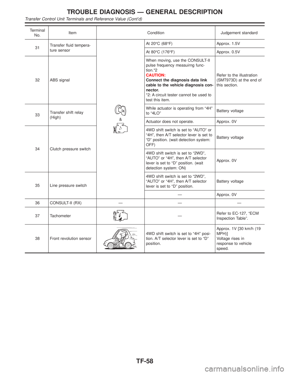
Terminal
No.Item Condition Judgement standard
31Transfer fluid tempera-
ture sensor
&
At 20ÉC (68ÉF) Approx. 1.5V
At 80ÉC (176ÉF) Approx. 0.5V
32 ABS signalWhen moving, use the CONSULT-II
pulse frequency measuirng func-
tion.*2
CAUTION:
Connect the diagnosis data link
cable to the vehicle diagnosis con-
nector.
*2: A circuit tester cannot be used to
test this item.Refer to the illustration
(SMT973D) at the end of
this section.
33Transfer shift relay
(High)While actuator is operating from ª4Hº
to ª4LOºBattery voltage
Actuator does not operate. Approx. 0V
34 Clutch pressure switch4WD shift switch is set to ªAUTOº or
ª4Hº, then A/T selector lever is set to
ªDº position. (wait detection system:
OFF)Battery voltage
4WD shift switch is set to ª2WDº,
ªAUTOº or ª4Hº, then A/T selector
lever is set to ªDº position. (wait
detection system: ON)Approx. 0V
35 Line pressure switch4WD shift switch is set to ª2WDº,
ªAUTOº or ª4Hº, then A/T selector
lever is set to ªDº position.Battery voltage
Ð Approx. 0V
36 CONSULT-II (RX) Ð Ð Ð
37 Tachometer
ÐRefer to EC-127, ªECM
Inspection Tableº.
38 Front revolution sensor
4WD shift switch is set to ª4Hº posi-
tion. A/T selector lever is set to ªDº
position.Approx. 1V [30 km/h (19
MPH)]
Voltage rises in
response to vehicle
speed.
TROUBLE DIAGNOSIS Ð GENERAL DESCRIPTION
Transfer Control Unit Terminals and Reference Value (Cont'd)
TF-58
Page 2296 of 2395

Diagnostic ProcedureNBTF0019
1 FRONT REVOLUTION SENSOR
Refer to ªFront Revolution Sensorº, ªCOMPONENT INSPECTIONº, TF-112.
OK or NG
OK©GO TO 3.
NG©GO TO 2.
2 CHECK CONTINUITY
Check the following.
IContinuity of transfer sub-harness
Refer to ªTransfer Sub-harnessº, ªCOMPONENT INSPECTIONº, TF-113.
OK or NG
OK©Repair or replace front revolution sensor.
NG©Repair or replace front revolution sensor and transfer sub-harness.
3 CHECK INPUT SIGNAL
WITH CONSULT-II©GO TO 4.
WITHOUT CONSULT-II©GO TO 5.
GI
MA
EM
LC
EC
FE
AT
PD
AX
SU
BR
ST
RS
BT
HA
SC
EL
IDX
VEHICLE SPEED SENSOR (FRONT REVOLUTION SENSOR)
Diagnostic Procedure
TF-61