Page 1318 of 2395
KEY SWITCH (INSERT) CHECK=NBEL0055S04
1 CHECK KEY SWITCH INPUT SIGNAL
Check voltage between smart entrance control unit terminal 32 and ground.
SEL307X
OK or NG
OK©Key switch is OK.
NG©GO TO 2.
2 CHECK KEY SWITCH (INSERT)
Check continuity between terminals 1 and 2.
SEL308X
OK or NG
OK©Check the following.
I7.5A fuse [No. 24, located in fuse block (J/B)]
IHarness for open or short between key switch and fuse
IHarness for open or short between smart entrance control unit and key switch
NG©Replace key switch.
GI
MA
EM
LC
EC
FE
AT
TF
PD
AX
SU
BR
ST
RS
BT
HA
SC
IDX
WARNING CHIME
Trouble Diagnoses (Cont'd)
EL-133
Page 1320 of 2395
DRIVER SIDE DOOR SWITCH CHECKNBEL0055S06
1 CHECK DOOR SWITCH INPUT SIGNAL
Check voltage between smart entrance control unit terminal 29 and ground.
SEL382X
OK or NG
OK©Front door switch LH is OK.
NG©GO TO 2.
2 CHECK DRIVER SIDE DOOR SWITCH
Check continuity between terminals 1 and 2.
SEL383X
OK or NG
OK©Check the following.
IDoor switch ground circuit
IHarness for open or short between smart entrance control unit and door switch
NG©Replace front door switch LH.
GI
MA
EM
LC
EC
FE
AT
TF
PD
AX
SU
BR
ST
RS
BT
HA
SC
IDX
WARNING CHIME
Trouble Diagnoses (Cont'd)
EL-135
Page 1322 of 2395
Ithrough terminal 17 of the wiper switch, and
Ithrough body grounds E13 and E41.
With power and ground supplied, the washer motor operates.
When the lever is pulled to the WASH position for one second or more, the wiper motor operates at low speed
for approximately 3 seconds to clean windshield. This feature is controlled by the wiper amplifier in the same
manner as the intermittent operation.
GI
MA
EM
LC
EC
FE
AT
TF
PD
AX
SU
BR
ST
RS
BT
HA
SC
IDX
FRONT WIPER AND WASHER
System Description (Cont'd)
EL-137
Page 1324 of 2395
SEL543TA
Removal and InstallationNBEL0060WIPER ARMSNBEL0060S011. Prior to wiper arm installation, turn on wiper switch to operate
wiper motor and then turn it ªOFFº (Auto Stop).
2. Lift the blade up and then set it down onto glass surface to set
the blade center to clearance ªL
1º&ªL2º immediately before
tightening nut.
3. Eject washer fluid. Turn on wiper switch to operate wiper motor
and then turn it ªOFFº.
4. Ensure that wiper blades stop within clearance ªL
1º&ªL2º.
Clearance ªL
1º: 29 - 30 mm (1.14 - 1.18 in)
Clearance ªL
2º: 32 - 42 mm (1.26 - 1.65 in)
ITighten wiper arm nuts to specified torque.
Front wiper: 21 - 26 N´m (2.1 - 2.7 kg-m, 15 - 20 ft-lb)
SEL024J
IBefore reinstalling wiper arm, clean up the pivot area as
illustrated. This will reduce possibility of wiper arm loose-
ness.
WIPER LINKAGENBEL0060S02
MEL840F
GI
MA
EM
LC
EC
FE
AT
TF
PD
AX
SU
BR
ST
RS
BT
HA
SC
IDX
FRONT WIPER AND WASHER
Removal and Installation
EL-139
Page 1326 of 2395

System DescriptionNBEL0063WIPER OPERATIONNBEL0063S01Power Supply and GroundNBEL0063S0101With ignition switch in the ACC or ON position, power is supplied
Ithrough 10A fuse [No. 29, located in the fuse block (J/B)]
Ito rear wiper amp. terminal 6.
When the glass hatch switch is OPEN, ground is supplied
Ito rear wiper amp. terminal 3
Ithrough glass hatch switch terminal 1 and 2
Ithrough body grounds B11, B22 and D210.
Ground is supplied
Ito rear wiper amp. terminal 9
Ithrough body grounds B11, B22 and D210.
Low Speed Wiper OperationNBEL0063S0103When the rear wiper switch is turned ON, ground is supplied
Ito rear wiper amp. terminal 2
Ithrough combination switch terminals 22 and 24.
Ithrough body grounds E13 and E41
Then, power is supplied
Ithrough rear wiper amp. terminal 11
Ito rear wiper motor terminal 4.
Ground is supplied
Ito rear wiper motor terminal 3
Ithrough rear wiper amp. terminal 8.
With power and ground supplied, the wiper motor operates at low speed.
Auto Stop OperationNBEL0063S0104With rear wiper switch turned OFF, rear wiper motor will continue to operate until wiper arm reaches rear wiper
stopper.
When rear wiper arm is not located at rear wiper stopper with wiper switch OFF, ground is supplied
Ito rear wiper amp. terminal 10
Ithrough wiper motor terminals 7 and 8
Ithrough body grounds B11, B22 and D210.
Then rear wiper motor continues to operate until wiper arm reaches bottom.
When wiper arm reaches bottom, power is supplied
Ithrough 10A fuse [No. 29, located in the fuse block (J/B)]
Ithrough rear wiper motor terminals 6 and 7 and
Ithrough rear wiper amp. terminals 10 and 8
Ito rear wiper motor terminal 3.
Ground is supplied
Ito rear wiper motor 4
Ithrough rear wiper amp. terminal 11.
Then wiper motor turns the other way and wiper arm moves once until wiper arm reaches stopper.
Intermittent OperationNBEL0063S0105The rear wiper motor operates the wiper arms at low speed approximately every 7 seconds. This feature is
controlled by the wiper amp.
When the wiper switch is placed in the INT position, ground is supplied
Ito wiper amp. terminal 4
Ithrough rear combination switch terminal 21 and 24
Ithrough body grounds E13 and E41.
Then, power is supplied
Ithrough rear wiper amp. terminal 11
GI
MA
EM
LC
EC
FE
AT
TF
PD
AX
SU
BR
ST
RS
BT
HA
SC
IDX
REAR WIPER AND WASHER
System Description
EL-141
Page 1328 of 2395
Wiring Diagram Ð WIP/R ÐNBEL0065
MEL809L
GI
MA
EM
LC
EC
FE
AT
TF
PD
AX
SU
BR
ST
RS
BT
HA
SC
IDX
REAR WIPER AND WASHER
Wiring Diagram Ð WIP/R Ð
EL-143
Page 1330 of 2395

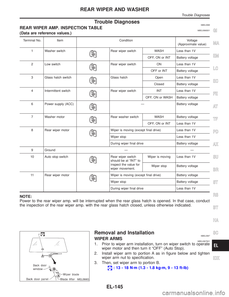
Trouble DiagnosesNBEL0066REAR WIPER AMP. INSPECTION TABLENBEL0066S01(Data are reference values.)
Terminal No. Item Condition Voltage
(Approximate value)
1 Washer switch
Rear wiper switch WASH Less than 1V
OFF, ON or INT Battery voltage
2 Low switch
Rear wiper switch ON Less than 1V
OFF or INT Battery voltage
3 Glass hatch switch
Glass hatch Open Less than 1V
Closed Battery voltage
4 Intermittent switch
Rear wiper switch INT Less than 1V
OFF, ON or WASH Battery voltage
6 Power supply (ACC)
Ð Battery voltage
7 Washer motor
Rear washer switch WASH Battery voltage
OFF, ON or INT Less than 1V
8 Rear wiper motor
Wiper is moving (except final drive) Less than 1V
Wiper stop Less than 1V
During wiper final drive Battery voltage
9 Ground Ð Ð
10 Auto stop switch
Rear wiper switch
should be at ªINTº to
inspect the value for
wiper movement.Wiper is moving Less than 1V
Wiper stop Battery voltage
11 Rear wiper motor
Wiper is moving (except final drive) Battery voltage
Wiper stop Battery voltage
During wiper final drive Less than 1V
NOTE:
Power to the rear wiper amp. will be interrupted when the rear glass hatch is opened. In that case, conduct
the inspection of the rear wiper amp. with the rear glass hatch closed, unless otherwise indicated.
MEL066G
Removal and InstallationNBEL0067WIPER ARMSNBEL0067S011. Prior to wiper arm installation, turn on wiper switch to operate
wiper motor and then turn it ªOFFº (Auto Stop).
2. Install wiper arm to portion A as in figure below and tighten
wiper arm nut to specification.
3. Then, set wiper arm to portion B.
: 13 - 18 N´m (1.3 - 1.8 kg-m,9-13ft-lb)
GI
MA
EM
LC
EC
FE
AT
TF
PD
AX
SU
BR
ST
RS
BT
HA
SC
IDX
REAR WIPER AND WASHER
Trouble Diagnoses
EL-145
Page 1332 of 2395
Wiring Diagram Ð HORN ÐNBEL0071
MEL811L
GI
MA
EM
LC
EC
FE
AT
TF
PD
AX
SU
BR
ST
RS
BT
HA
SC
IDX
HORN
Wiring Diagram Ð HORN Ð
EL-147