2001 INFINITI QX4 engine
[x] Cancel search: enginePage 1716 of 2395
SEM455G
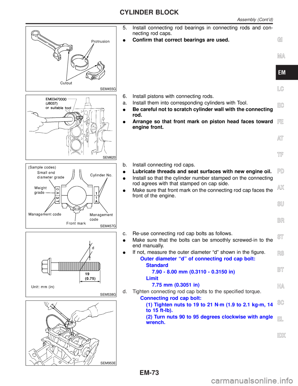
5. Install connecting rod bearings in connecting rods and con-
necting rod caps.
IConfirm that correct bearings are used.
SEM620
6. Install pistons with connecting rods.
a. Install them into corresponding cylinders with Tool.
IBe careful not to scratch cylinder wall with the connecting
rod.
IArrange so that front mark on piston head faces toward
engine front.
SEM457G
b. Install connecting rod caps.
ILubricate threads and seat surfaces with new engine oil.
IInstall so that the cylinder number stamped on the connecting
rod agrees with that stamped on cap side.
IMake sure that front mark on the connecting rod cap faces the
front of the engine.
SEM538G
SEM953E
c. Re-use connecting rod cap bolts as follows.
IMake sure that the bolts can be smoothly screwed-in to the
end manually.
IIf not, measure the outer diameter ªdº shown in the figure.
Outer diameter ªdº of connecting rod cap bolt:
Standard
7.90 - 8.00 mm (0.3110 - 0.3150 in)
Limit
7.75 mm (0.3051 in)
d. Tighten connecting rod cap bolts to the specified torque.
Connecting rod cap bolt:
(1) Tighten nuts to 19 to 21 N´m (1.9 to 2.1 kg-m, 14
to 15 ft-lb).
(2) Turn nuts 90 to 95 degrees clockwise with angle
wrench.
GI
MA
LC
EC
FE
AT
TF
PD
AX
SU
BR
ST
RS
BT
HA
SC
EL
IDX
CYLINDER BLOCK
Assembly (Cont'd)
EM-73
Page 1733 of 2395
Removal and InstallationNBFE0004WARNING:
When replacing fuel line parts, be sure to observe the follow-
ing:
IPut a ªCAUTION: INFLAMMABLEº sign in workshop.
IDo not smoke while servicing fuel system. Keep open
flames and sparks away from work area.
IBe sure to furnish the workshop with a CO
2fire extin-
guisher.
CAUTION:
IBefore removing fuel line parts, carry out the following
procedures:
a) Put drained fuel in an explosion-proof container and put
lid on securely.
b) Release fuel pressure from fuel line. Refer to MA-16,
ªChanging Fuel Filterº.
c) Disconnect battery ground cable.
IAlways replace O-ring with new ones.
IDo not kink or twist hose and tube when they are installed.
IDo not tighten hose clamps excessively to avoid damag-
ing hoses.
IWhen installing fuel check valve, be careful of its desig-
nated direction. Refer to EC-32, ªEVAPORATIVE EMIS-
SION SYSTEMº.
IAfter installation, run engine and check for fuel leaks at
connections.
FUEL SYSTEM
Removal and Installation
FE-4
Page 1736 of 2395
SFE544A
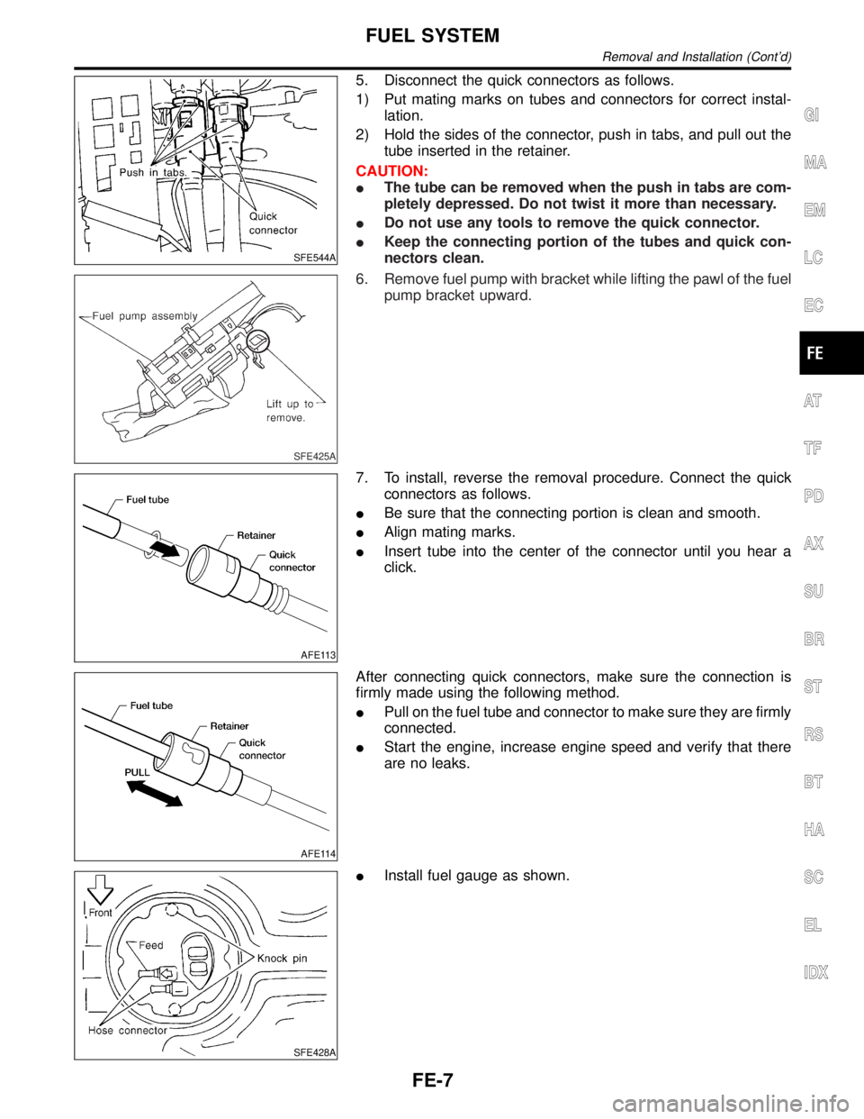
5. Disconnect the quick connectors as follows.
1) Put mating marks on tubes and connectors for correct instal-
lation.
2) Hold the sides of the connector, push in tabs, and pull out the
tube inserted in the retainer.
CAUTION:
IThe tube can be removed when the push in tabs are com-
pletely depressed. Do not twist it more than necessary.
IDo not use any tools to remove the quick connector.
IKeep the connecting portion of the tubes and quick con-
nectors clean.
SFE425A
6. Remove fuel pump with bracket while lifting the pawl of the fuel
pump bracket upward.
AFE113
7. To install, reverse the removal procedure. Connect the quick
connectors as follows.
IBe sure that the connecting portion is clean and smooth.
IAlign mating marks.
IInsert tube into the center of the connector until you hear a
click.
AFE114
After connecting quick connectors, make sure the connection is
firmly made using the following method.
IPull on the fuel tube and connector to make sure they are firmly
connected.
IStart the engine, increase engine speed and verify that there
are no leaks.
SFE428A
IInstall fuel gauge as shown.
GI
MA
EM
LC
EC
AT
TF
PD
AX
SU
BR
ST
RS
BT
HA
SC
EL
IDX
FUEL SYSTEM
Removal and Installation (Cont'd)
FE-7
Page 1737 of 2395
Removal and InstallationNBFE0005CAUTION:
IAlways replace exhaust gaskets with new ones when reassembling.
IWith engine running, check all tube connections for exhaust gas leaks, and entire system for
unusual noises.
ICheck to ensure that mounting brackets and mounting insulators are installed properly and free
from undue stress. Improper installation could result in excessive noise or vibration.
IDiscard any heated oxygen sensor which has been dropped from a height of more than 0.5 m (19.7
in) onto a hard surface such as a concrete floor; use a new one.
IBefore installing new oxygen sensor, clean exhaust system threads using Oxygen Sensor Thread
Cleaner tool J-43897-18 of J-43897-12 and approved anti-seize lubricant.
IDo not overtorque the oxygen sensor. Doing so may cause damage to the oxygen sensor, result-
ing in the MIL coming on.
EXHAUST SYSTEM
Removal and Installation
FE-8
Page 1745 of 2395
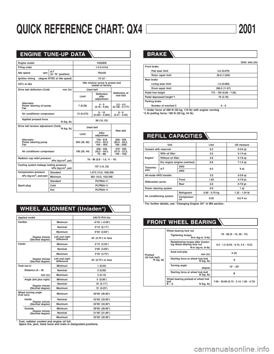
QUICK REFERENCE CHART: QX42001
Engine model VQ35DE
Firing order 1-2-3-4-5-6
Idle speed rpmA/T
(in ªNº position)750 50
Ignition timing (degree BTDC at idle speed) 15É 2É
CO% at idleIdle mixture screw is preset and
sealed at factory.
Drive belt deflection (Cold) mm (in) Used belt
Deflection of
new belt
LimitDeflection
after
adjustment
Alternator
Power steering oil pump
Fan7 (0.28)4-5
(0.16 - 0.20)3.5 - 4.5
(0.138 - 0.177)
Air conditioner compressor 12 (0.472)9-10
(0.354 - 0.394)8-9
(0.31 - 0.35)
Applied pressed force
N (kg, lb)98 (10, 22)
Drive belt tension adjustment (Cold)
N (kg, lb)Used belt
New belt
LimitAfter
adjustment
Alternator
Power steering pump
Fan294 (30, 66)730 - 818
(74.4 - 83.5,
164 - 184)838 - 926
(85.4 - 94.5,
188 - 208)
Air conditioner compressor 196 (20, 44)348 - 436
(35.5 - 44.5,
78 - 98)470 - 559
(47.9 - 57.0,
106 - 126)
Radiator cap relief pressure
kPa (kg/cm
2, psi)78 - 98 (0.8 - 1.0, 11 - 14)
Cooling system leakage testing pressure
kPa (kg/cm
2, psi)157 (1.6, 23)
Compression pressure
kPa (kg/cm
2, psi)/rpmStandard 1,275 (13.0, 185)/300
Minimum 981 (10.0, 142)/300
Spark plugStandard PLFR5A-11
Cold PLFR6A-11
Hot PLFR4A-11
Applied model 245/70 R16 tire
Camber
Degree minute
(Decimal degree)Minimum þ0É35¢(þ0.58É)
Nominal 0É10¢(0.17É)
Maximum 0É55¢(0.92É)
Left and right
difference45¢(0.75É) or less
Caster
Degree minute
(Decimal degree)Minimum 2É15¢(2.25É)
Nominal 3É00¢(3.00É)
Maximum 3É45¢(3.75É)
Left and right
difference45¢(0.75É) or less
Total toe-in Minimum 1 (0.04)
Distance (A þ B)
mm (in)Nominal 2 (0.08)
Maximum 3 (0.12)
Angle (left plus right)
Degree minute
(Decimal degree)Minimum 5¢(0.08É)
Nominal 10¢(0.17É)
Maximum 15¢(0.25É)
Wheel turning angle
(Full turn)Minimum 30É00¢(30.00É)
Inside
Degree minute
(Decimal degree)Nominal 33É00¢(33.00É)
Maximum 34É00¢(34.00É)
Outside
Degree minute
(Decimal degree)Minimum 28É00¢(28.00É)
Nominal 31É00¢(31.00É)
Maximum 32É00¢(32.00É)
* Fuel, radiator coolant and engine oil full.
Spare tire, jack, hand tools and mats in designated positions.
Unit: mm (in)Front brake
Pad wear limit 2.0 (0.079)
Rotor repair limit 26.0 (1.024)
Rear brake
Lining wear limit 1.5 (0.059)
Drum repair limit 296.5 (11.67)
Pedal free height 175 - 185 (6.89 - 7.28)
Pedal depressed height*1 70 (2.76)
Parking brake
Number of notches*2 6 - 8
*1 Under force of 490 N (50 kg, 110 lb) with engine running
*2 At pulling force: 196 N (20 kg, 44 lb)
Unit Liter US measure
Coolant with reservoir 9.2 9-3/4 qt
Engine*With oil filter 5.0 5-1/4 qt
Without oil filter 4.8 5-1/8 qt
Dry engine (engine overhaul) 6.8 7-1/4 qt
Transmis-
sionA/T2WD
8.5 9 qt
4WD
All-mode 4WD transfer 3.0 2-5/8 qt
Differential carrierFront 1.85 3-7/8 pt
Rear 2.8 5-7/8 pt
Power steering system 0.9 1 qt
Air conditioning systemRefrigerant 0.60 - 0.70 kg 1.32 - 1.54 lb
Compressor
oil0.20 6.8 fl oz
* For further details, see ªChanging Engine Oilº in MA section.
Preload
(At hub bolt)
N (kg, lb)Wheel bearing lock nut
78-98(8-10,58-72)
Tightening torque
N×m (kg-m, ft-lb)
Retightening torque after loosen-
ing wheel bearing lock nut
N×m (kg-m, in-lb)0.5 - 1.5 (0.05 - 0.15, 4.3 - 13.0)
Axial end play
mm (in)0 (0)
Starting force at wheel hub bolt
N (kg, lb)A
Turning angle
degree15É - 30É
Starting force at wheel hub bolt
N (kg, lb)B
Wheel bearing preload at wheel hub
bolt
B þ A N (kg, lb)7.06 - 20.99 (0.72 - 2.14, 1.59 - 4.72)
Page 1746 of 2395
GENERAL INFORMATION
SECTION
GI
CONTENTS
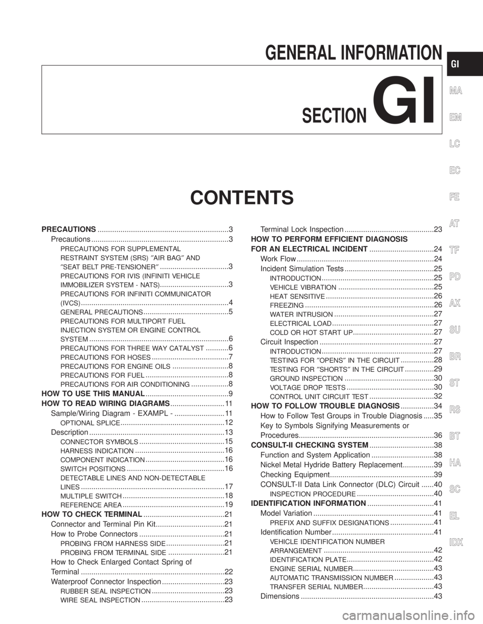
PRECAUTIONS...............................................................3
Precautions ..................................................................3
PRECAUTIONS FOR SUPPLEMENTAL
RESTRAINT SYSTEM (SRS)²AIR BAG²AND
²SEAT BELT PRE-TENSIONER²
.................................3
PRECAUTIONS FOR IVIS (INFINITI VEHICLE
IMMOBILIZER SYSTEM - NATS)
.................................3
PRECAUTIONS FOR INFINITI COMMUNICATOR
(IVCS)
.......................................................................4
GENERAL PRECAUTIONS.........................................5
PRECAUTIONS FOR MULTIPORT FUEL
INJECTION SYSTEM OR ENGINE CONTROL
SYSTEM
...................................................................6
PRECAUTIONS FOR THREE WAY CATALYST...........6
PRECAUTIONS FOR HOSES.....................................7
PRECAUTIONS FOR ENGINE OILS...........................8
PRECAUTIONS FOR FUEL........................................8
PRECAUTIONS FOR AIR CONDITIONING..................8
HOW TO USE THIS MANUAL........................................9
HOW TO READ WIRING DIAGRAMS.......................... 11
Sample/Wiring Diagram - EXAMPL - ........................ 11
OPTIONAL SPLICE..................................................12
Description .................................................................13
CONNECTOR SYMBOLS.........................................15
HARNESS INDICATION...........................................16
COMPONENT INDICATION......................................16
SWITCH POSITIONS...............................................16
DETECTABLE LINES AND NON-DETECTABLE
LINES
.....................................................................17
MULTIPLE SWITCH.................................................18
REFERENCE AREA.................................................19
HOW TO CHECK TERMINAL.......................................21
Connector and Terminal Pin Kit.................................21
How to Probe Connectors .........................................21
PROBING FROM HARNESS SIDE............................21
PROBING FROM TERMINAL SIDE...........................21
How to Check Enlarged Contact Spring of
Terminal .....................................................................22
Waterproof Connector Inspection ..............................23
RUBBER SEAL INSPECTION...................................23
WIRE SEAL INSPECTION........................................23Terminal Lock Inspection ...........................................23
HOW TO PERFORM EFFICIENT DIAGNOSIS
FOR AN ELECTRICAL INCIDENT...............................24
Work Flow ..................................................................24
Incident Simulation Tests ...........................................25
INTRODUCTION......................................................25
VEHICLE VIBRATION..............................................25
HEAT SENSITIVE....................................................26
FREEZING..............................................................26
WATER INTRUSION................................................27
ELECTRICAL LOAD.................................................27
COLD OR HOT START UP.......................................27
Circuit Inspection .......................................................27
INTRODUCTION......................................................27
TESTING FOR²OPENS²IN THE CIRCUIT................28
TESTING FOR²SHORTS²IN THE CIRCUIT..............29
GROUND INSPECTION...........................................30
VOLTAGE DROP TESTS..........................................30
CONTROL UNIT CIRCUIT TEST...............................32
HOW TO FOLLOW TROUBLE DIAGNOSIS................34
How to Follow Test Groups in Trouble Diagnosis .....35
Key to Symbols Signifying Measurements or
Procedures.................................................................36
CONSULT-II CHECKING SYSTEM...............................38
Function and System Application ..............................38
Nickel Metal Hydride Battery Replacement...............39
Checking Equipment..................................................39
CONSULT-II Data Link Connector (DLC) Circuit ......40
INSPECTION PROCEDURE.....................................40
IDENTIFICATION INFORMATION................................41
Model Variation ..........................................................41
PREFIX AND SUFFIX DESIGNATIONS.....................41
Identification Number .................................................41
VEHICLE IDENTIFICATION NUMBER
ARRANGEMENT
.....................................................42
IDENTIFICATION PLATE..........................................42
ENGINE SERIAL NUMBER.......................................43
AUTOMATIC TRANSMISSION NUMBER...................43
TRANSFER SERIAL NUMBER..................................43
Dimensions ................................................................43
MA
EM
LC
EC
FE
AT
TF
PD
AX
SU
BR
ST
RS
BT
HA
SC
EL
IDX
Page 1748 of 2395
PrecautionsNBGI0001Observe the following precautions to ensure safe and proper
servicing. These precautions are not described in each indi-
vidual section.
SGI646
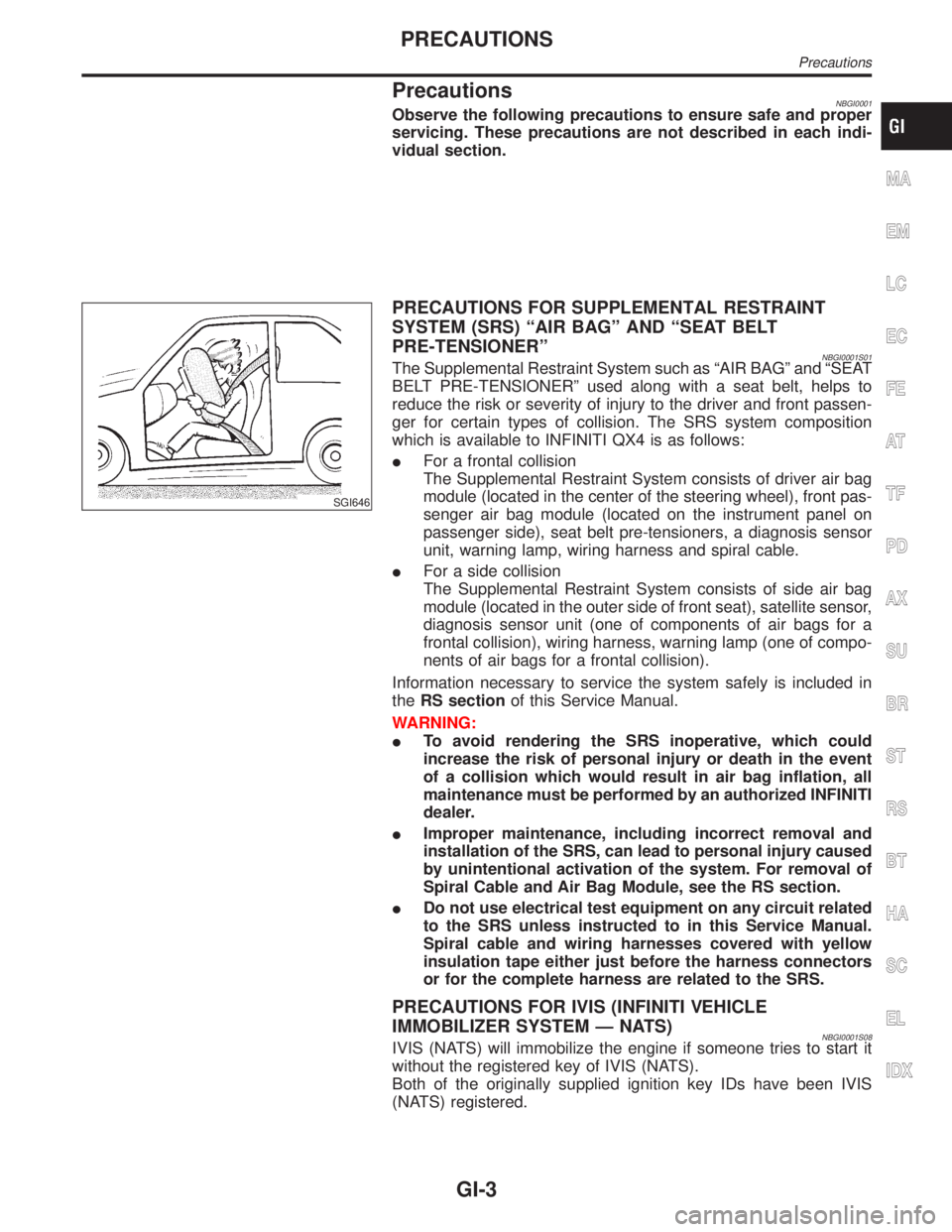
PRECAUTIONS FOR SUPPLEMENTAL RESTRAINT
SYSTEM (SRS) ªAIR BAGº AND ªSEAT BELT
PRE-TENSIONERº
NBGI0001S01The Supplemental Restraint System such as ªAIR BAGº and ªSEAT
BELT PRE-TENSIONERº used along with a seat belt, helps to
reduce the risk or severity of injury to the driver and front passen-
ger for certain types of collision. The SRS system composition
which is available to INFINITI QX4 is as follows:
IFor a frontal collision
The Supplemental Restraint System consists of driver air bag
module (located in the center of the steering wheel), front pas-
senger air bag module (located on the instrument panel on
passenger side), seat belt pre-tensioners, a diagnosis sensor
unit, warning lamp, wiring harness and spiral cable.
IFor a side collision
The Supplemental Restraint System consists of side air bag
module (located in the outer side of front seat), satellite sensor,
diagnosis sensor unit (one of components of air bags for a
frontal collision), wiring harness, warning lamp (one of compo-
nents of air bags for a frontal collision).
Information necessary to service the system safely is included in
theRS sectionof this Service Manual.
WARNING:
ITo avoid rendering the SRS inoperative, which could
increase the risk of personal injury or death in the event
of a collision which would result in air bag inflation, all
maintenance must be performed by an authorized INFINITI
dealer.
IImproper maintenance, including incorrect removal and
installation of the SRS, can lead to personal injury caused
by unintentional activation of the system. For removal of
Spiral Cable and Air Bag Module, see the RS section.
IDo not use electrical test equipment on any circuit related
to the SRS unless instructed to in this Service Manual.
Spiral cable and wiring harnesses covered with yellow
insulation tape either just before the harness connectors
or for the complete harness are related to the SRS.
PRECAUTIONS FOR IVIS (INFINITI VEHICLE
IMMOBILIZER SYSTEM Ð NATS)
NBGI0001S08IVIS (NATS) will immobilize the engine if someone tries to start it
without the registered key of IVIS (NATS).
Both of the originally supplied ignition key IDs have been IVIS
(NATS) registered.
MA
EM
LC
EC
FE
AT
TF
PD
AX
SU
BR
ST
RS
BT
HA
SC
EL
IDX
PRECAUTIONS
Precautions
GI-3
Page 1749 of 2395
The security indicator is located on the instrument panel. The indi-
cator blinks when the ignition switch is in OFF or ACC position.
Therefore, IVIS (NATS) warns outsiders that the vehicle is
equipped with the anti-theft system.
IWhen IVIS (NATS) detects trouble, the security indicator lamp
lights up while ignition switch is in ON position.
This lighting up indicates that the anti-theft is not functioning,
so prompt service is required.
IWhen servicing IVIS (NATS) (trouble diagnoses, system initial-
ization and additional registration of other IVIS (NATS) ignition
key IDs), CONSULT-II hardware and CONSULT-II IVIS (NATS)
software is necessary.
Regarding the procedures of IVIS (NATS) initialization and
IVIS (NATS) ignition key ID registration, refer to CONSULT-II
operation manual, IVIS/NVIS.
Therefore, CONSULT-II IVIS (NATS) software (program card
and operation manual) must be kept strictly confidential to
maintain the integrity of the anti-theft function.
IWhen servicing IVIS (NATS) (trouble diagnoses, system initial-
ization and additional registration of other IVIS (NATS) ignition
key IDs), it may be necessary to re-register original key iden-
tification. Therefore, be sure to receive all keys from vehicle
owner.
A maximum of five key IDs can be registered into IVIS (NATS).
IWhen failing to start the engine first time using the key of IVIS
(NATS) (for example, when interference is caused by another
IVIS (NATS) key, an automated full road device or automated
payment device on the key ring), restart as follows.
a) Leave the ignition switch in ON position for approximately 5
seconds.
b) Turn ignition switch to OFF or LOCK position and wait approxi-
mately 5 seconds.
c) Repeat step 1 and 2.
d) Restart the engine while holding the device (which may have
caused the interference) separate from the registered NATS
key. If the no start condition re-occurs, NISSAN recommends
placing the registered IVIS (NATS) key on a separate key ring
to avoid interference from other devices.
PRECAUTIONS FOR INFINITI COMMUNICATOR (IVCS)NBGI0001S09The purpose of INFINITI Communicator is to increase security for
the vehicle owner by providing a convenient way to contact the
most appropriate emergency assistance provider during an emer-
gency.
Improper operation of the system may result in a police response.
The theft warning system also activates INFINITI Communicator.
For details, refer to INFINITI Communicator (IVCS) in the EL sec-
tion.
PRECAUTIONS
Precautions (Cont'd)
GI-4