Page 900 of 2395

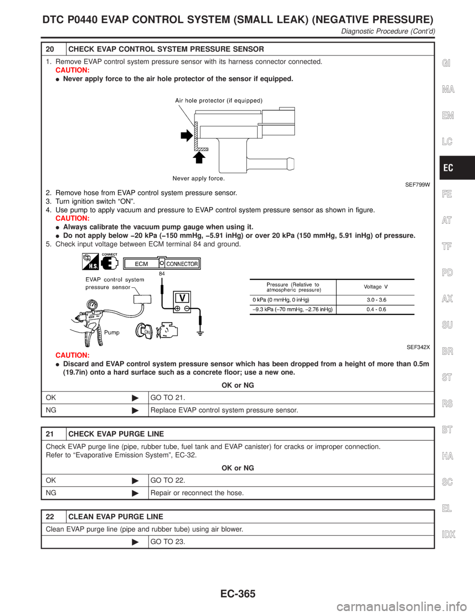
20 CHECK EVAP CONTROL SYSTEM PRESSURE SENSOR
1. Remove EVAP control system pressure sensor with its harness connector connected.
CAUTION:
INever apply force to the air hole protector of the sensor if equipped.
SEF799W
2. Remove hose from EVAP control system pressure sensor.
3. Turn ignition switch ªONº.
4. Use pump to apply vacuum and pressure to EVAP control system pressure sensor as shown in figure.
CAUTION:
IAlways calibrate the vacuum pump gauge when using it.
IDo not apply below þ20 kPa (þ150 mmHg, þ5.91 inHg) or over 20 kPa (150 mmHg, 5.91 inHg) of pressure.
5. Check input voltage between ECM terminal 84 and ground.
SEF342X
CAUTION:
IDiscard and EVAP control system pressure sensor which has been dropped from a height of more than 0.5m
(19.7in) onto a hard surface such as a concrete floor; use a new one.
OK or NG
OK©GO TO 21.
NG©Replace EVAP control system pressure sensor.
21 CHECK EVAP PURGE LINE
Check EVAP purge line (pipe, rubber tube, fuel tank and EVAP canister) for cracks or improper connection.
Refer to ªEvaporative Emission Systemº, EC-32.
OK or NG
OK©GO TO 22.
NG©Repair or reconnect the hose.
22 CLEAN EVAP PURGE LINE
Clean EVAP purge line (pipe and rubber tube) using air blower.
©GO TO 23.
GI
MA
EM
LC
FE
AT
TF
PD
AX
SU
BR
ST
RS
BT
HA
SC
EL
IDX
DTC P0440 EVAP CONTROL SYSTEM (SMALL LEAK) (NEGATIVE PRESSURE)
Diagnostic Procedure (Cont'd)
EC-365
Page 901 of 2395
23 CHECK FUEL LEVEL SENSOR
Refer to EL-108, ªFuel Level Sensor Unit Checkº.
OK or NG
OK©GO TO 24.
NG©Replace fuel level sensor unit.
24 CHECK INTERMITTENT INCIDENT
Refer to ªTROUBLE DIAGNOSIS FOR INTERMITTENT INCIDENTº, EC-140.
©INSPECTION END
DTC P0440 EVAP CONTROL SYSTEM (SMALL LEAK) (NEGATIVE PRESSURE)
Diagnostic Procedure (Cont'd)
EC-366
Page 918 of 2395

SEF194Y
SEF340X
WITH CONSULT-IINBEC0239S011) Start engine and warm it up to normal operating temperature.
2) Turn ignition switch ªOFFº and wait at least 10 seconds.
3) Turn ignition switch ªONº.
4) Select ªDATA MONITORº mode with CONSULT-II.
5) Make sure that ªFUEL T/TEMP SEº is more than 0ÉC (32ÉF).
6) Start engine and wait at least 20 seconds.
7) If 1st trip DTC is detected, go to ªDiagnostic Procedureº,
EC-385.
WITH GSTNBEC0239S021) Start engine and warm it up to normal operating temperature.
2) Check that voltage between ECM terminal 92 (Fuel tank tem-
perature sensor signal) and ground is less than 4.2V.
3) Turn ignition switch ªOFFº and wait at least 10 seconds.
4) Start engine and wait at least 20 seconds.
5) Select ªMODE 7º with GST.
6) If 1st trip DTC is detected, go to ªDiagnostic Procedureº,
EC-385.
GI
MA
EM
LC
FE
AT
TF
PD
AX
SU
BR
ST
RS
BT
HA
SC
EL
IDX
DTC P0450 EVAPORATIVE EMISSION (EVAP) CONTROL SYSTEM PRESSURE
SENSOR
DTC Confirmation Procedure (Cont'd)
EC-383
Page 930 of 2395
IEVAP purge line rubber tube bent.
IBlocked or bent rubber tube to EVAP control system pressure
sensor
ILoose or disconnected rubber tube
IEVAP canister vent control valve and the circuit
IEVAP canister purge volume control solenoid valve and the
circuit
IAbsolute pressure sensor
IFuel tank temperature sensor
IO-ring of EVAP canister vent control valve is missing or dam-
aged.
IEVAP control system pressure sensor
GI
MA
EM
LC
FE
AT
TF
PD
AX
SU
BR
ST
RS
BT
HA
SC
EL
IDX
DTC P0455 EVAP CONTROL SYSTEM (GROSS LEAK)
Possible Cause (Cont'd)
EC-395
Page 933 of 2395
3 CHECK FUEL FILLER CAP FUNCTION
Check for air releasing sound while opening the fuel filler cap.
OK or NG
OK©GO TO 5.
NG©GO TO 4.
4 CHECK FUEL TANK VACUUM RELIEF VALVE
1. Wipe clean valve housing.
2. Check valve opening pressure and vacuum.
SEF427N
SEF943S
Pressure:
15.3 - 20.0 kPa (0.156 - 0.204 kg/cm2, 2.22 - 2.90 psi)
Vacuum:
þ6.0 to þ3.3 kPa (þ0.061 to þ0.034 kg/cm
2, þ0.87 to þ0.48 psi)
CAUTION:
Use only a genuine fuel filler cap as a replacement. If an incorrect fuel filler cap is used, the MIL may come on.
OK or NG
OK©GO TO 5.
NG©Replace fuel filler cap with a genuine one.
5 CHECK EVAP PURGE LINE
Check EVAP purge line (pipe, rubber tube, fuel tank and EVAP canister) for cracks, improper connection or disconnection.
Refer to ªEvaporative Emission Systemº, EC-32.
OK or NG
OK©GO TO 6.
NG©Repair or reconnect the hose.
DTC P0455 EVAP CONTROL SYSTEM (GROSS LEAK)
Diagnostic Procedure (Cont'd)
EC-398
Page 940 of 2395

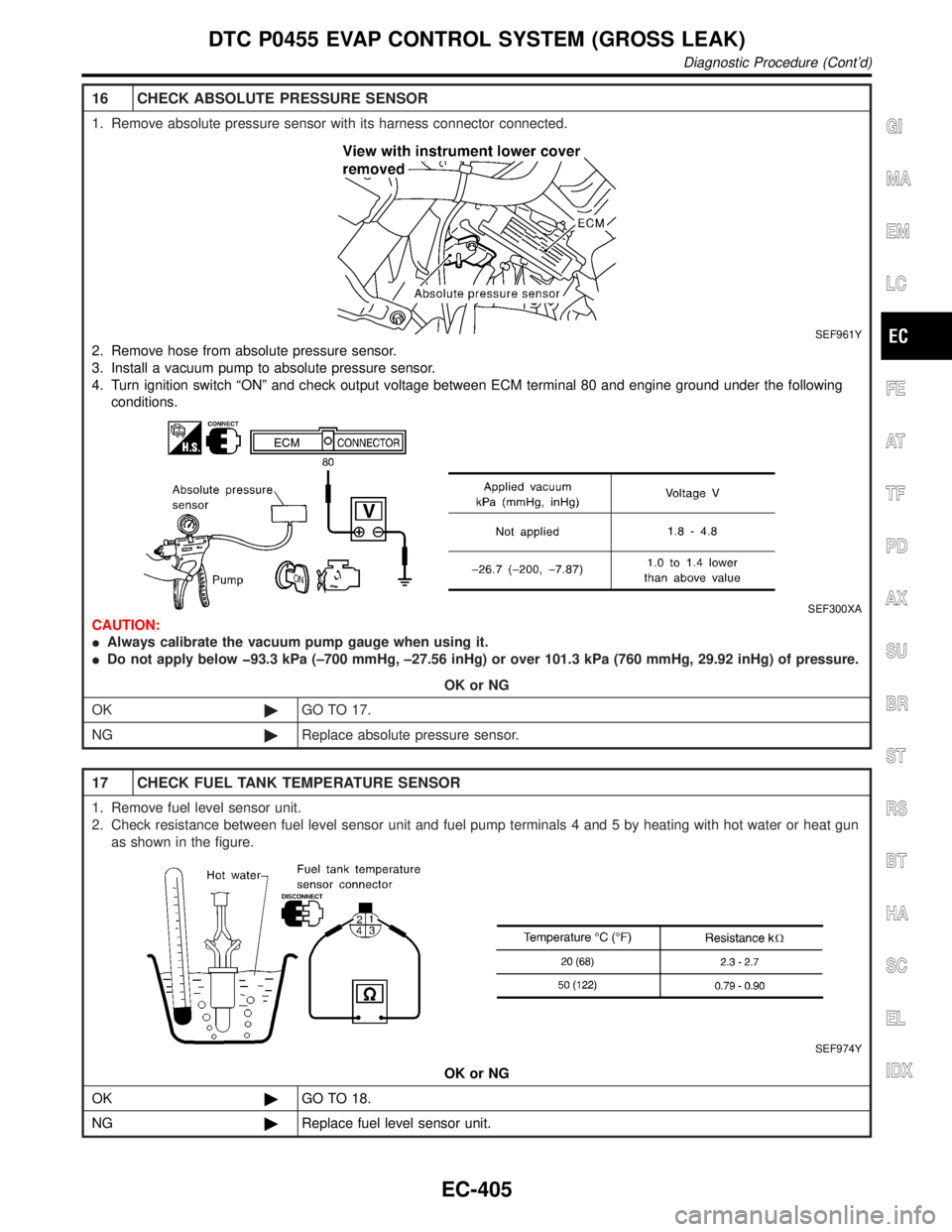
16 CHECK ABSOLUTE PRESSURE SENSOR
1. Remove absolute pressure sensor with its harness connector connected.
SEF961Y
2. Remove hose from absolute pressure sensor.
3. Install a vacuum pump to absolute pressure sensor.
4. Turn ignition switch ªONº and check output voltage between ECM terminal 80 and engine ground under the following
conditions.
SEF300XA
CAUTION:
IAlways calibrate the vacuum pump gauge when using it.
IDo not apply below þ93.3 kPa (±700 mmHg, ±27.56 inHg) or over 101.3 kPa (760 mmHg, 29.92 inHg) of pressure.
OK or NG
OK©GO TO 17.
NG©Replace absolute pressure sensor.
17 CHECK FUEL TANK TEMPERATURE SENSOR
1. Remove fuel level sensor unit.
2. Check resistance between fuel level sensor unit and fuel pump terminals 4 and 5 by heating with hot water or heat gun
as shown in the figure.
SEF974Y
OK or NG
OK©GO TO 18.
NG©Replace fuel level sensor unit.
GI
MA
EM
LC
FE
AT
TF
PD
AX
SU
BR
ST
RS
BT
HA
SC
EL
IDX
DTC P0455 EVAP CONTROL SYSTEM (GROSS LEAK)
Diagnostic Procedure (Cont'd)
EC-405
Page 946 of 2395

SEF018S
Component Description=NBEC0622The fuel level sensor is mounted in the fuel level sensor unit. The
sensor detects a fuel level in the fuel tank and transmits a signal
to the ECM.
It consists of two parts, one is mechanical float and the other side
is variable resistor. Fuel level sensor output voltage changes
depending on the movement of the fuel mechanical float.
On Board Diagnostic LogicNBEC0623Driving long distances naturally affect fuel gauge level.
This diagnosis detects the fuel gauge malfunction of the gauge not
moving even after a long distance has been driven.
Malfunction is detected when the output signal of the fuel level
sensor does not change within the specified range even though the
vehicle has been driven a long distance.
Possible CauseNBEC0624IHarness or connectors
(The level sensor circuit is open or shorted.)
IFuel level sensor
Overall Function CheckNBEC0625Use this procedure to check the overall function of the fuel level
sensor function. During this check, a 1st trip DTC might not be
confirmed.
WARNING:
When performing following procedure, be sure to observe the
handling of the fuel. Refer to FE-5, ªFuel Tankº.
TESTING CONDITION:
Before starting overall function check, preparation of draining
fuel and refilling fuel is required.
SEF195Y
WITH CONSULT-IINBEC0625S01NOTE:
Start from step 11, if it is possible to confirm that the fuel
cannot be drained by 30(7-7/8 US gal, 6-5/8 Imp gal) in
advance.
1) Prepare a fuel container and a spare hose.
2) Release fuel pressure from fuel line, refer to ªFuel Pressure
Releaseº, EC-39.
3) Remove the fuel feed hose on the fuel level sensor unit.
4) Connect a spare fuel hose where the fuel feed hose was
removed.
GI
MA
EM
LC
FE
AT
TF
PD
AX
SU
BR
ST
RS
BT
HA
SC
EL
IDX
DTC P0461 FUEL LEVEL SENSOR FUNCTION
Component Description
EC-411
Page 947 of 2395

5) Turn ignition switch ªOFFº and wait at least 10 seconds then
turn ªONº.
6) Select ªFUEL LEVEL SEº in ªDATA MONITORº mode with
CONSULT-II.
7) Check ªFUEL LEVEL SEº output voltage and note it.
8) Select ªFUEL PUMPº in ªACTIVE TESTº mode with CON-
SULT-II.
9) Touch ªONº and drain fuel approximately 30(7-7/8 US gal,
6-5/8 Imp gal) and stop it.
10) Fill fuel into the fuel tank for 30(7-7/8 US gal, 6-5/8 Imp gal).
11) Check ªFUEL LEVEL SEº output voltage and note it.
12) Check ªFUEL LEVEL SEº output voltage and confirm whether
the voltage changes more than 0.03V during step 7 to 11.
If NG, check the fuel level sensor, refer to EL-108, ªFUEL
LEVEL SENSOR UNIT CHECKº.
SEF615X
WITH GSTNBEC0625S02NOTE:
Start from step 11, if it is possible to confirm that the fuel
cannot be drained by 30(7-7/8 US gal, 6-5/8 Imp gal) in
advance.
1) Prepare a fuel container and a spare hose.
2) Release fuel pressure from fuel line, refer to ªFuel Pressure
Releaseº, EC-39.
3) Remove the fuel feed hose on the fuel level sensor unit.
4) Connect a spare fuel hose where the fuel feed hose was
removed.
5) Turn ignition switch ªOFFº.
6) Set voltmeters probe between ECM terminal 83 (fuel level
sensor signal) and ground.
7) Turn ignition switch ªONº.
8) Check voltage between ECM terminal 83 and ground and note
it.
9) Drain fuel by 30(7-7/8 US gal, 6-5/8 Imp gal) from the fuel
tank using proper equipment.
10) Fill fuel into the fuel tank for 30(7-7/8 US gal, 6-5/8 Imp gal).
11) Confirm that the voltage between ECM terminal 83 and ground
changes more than 0.03V during step8-10.
If NG, check component of fuel level sensor, refer to EL-108,
ªFUEL LEVEL SENSOR UNIT CHECKº.
DTC P0461 FUEL LEVEL SENSOR FUNCTION
Overall Function Check (Cont'd)
EC-412