2001 INFINITI QX4 fuel pressure
[x] Cancel search: fuel pressurePage 1751 of 2395
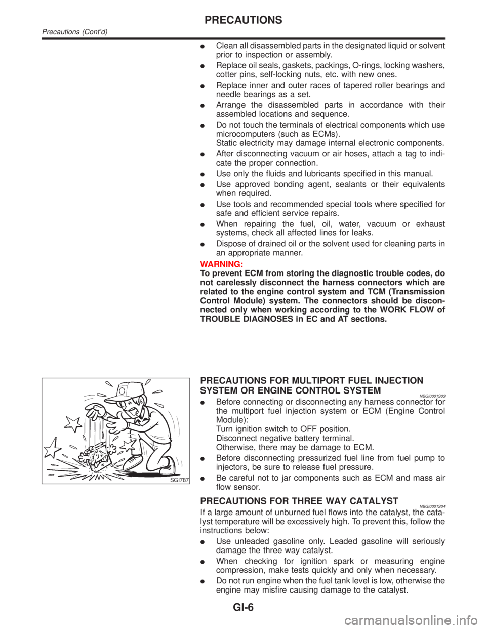
IClean all disassembled parts in the designated liquid or solvent
prior to inspection or assembly.
IReplace oil seals, gaskets, packings, O-rings, locking washers,
cotter pins, self-locking nuts, etc. with new ones.
IReplace inner and outer races of tapered roller bearings and
needle bearings as a set.
IArrange the disassembled parts in accordance with their
assembled locations and sequence.
IDo not touch the terminals of electrical components which use
microcomputers (such as ECMs).
Static electricity may damage internal electronic components.
IAfter disconnecting vacuum or air hoses, attach a tag to indi-
cate the proper connection.
IUse only the fluids and lubricants specified in this manual.
IUse approved bonding agent, sealants or their equivalents
when required.
IUse tools and recommended special tools where specified for
safe and efficient service repairs.
IWhen repairing the fuel, oil, water, vacuum or exhaust
systems, check all affected lines for leaks.
IDispose of drained oil or the solvent used for cleaning parts in
an appropriate manner.
WARNING:
To prevent ECM from storing the diagnostic trouble codes, do
not carelessly disconnect the harness connectors which are
related to the engine control system and TCM (Transmission
Control Module) system. The connectors should be discon-
nected only when working according to the WORK FLOW of
TROUBLE DIAGNOSES in EC and AT sections.
SGI787
PRECAUTIONS FOR MULTIPORT FUEL INJECTION
SYSTEM OR ENGINE CONTROL SYSTEM
NBGI0001S03IBefore connecting or disconnecting any harness connector for
the multiport fuel injection system or ECM (Engine Control
Module):
Turn ignition switch to OFF position.
Disconnect negative battery terminal.
Otherwise, there may be damage to ECM.
IBefore disconnecting pressurized fuel line from fuel pump to
injectors, be sure to release fuel pressure.
IBe careful not to jar components such as ECM and mass air
flow sensor.
PRECAUTIONS FOR THREE WAY CATALYSTNBGI0001S04If a large amount of unburned fuel flows into the catalyst, the cata-
lyst temperature will be excessively high. To prevent this, follow the
instructions below:
IUse unleaded gasoline only. Leaded gasoline will seriously
damage the three way catalyst.
IWhen checking for ignition spark or measuring engine
compression, make tests quickly and only when necessary.
IDo not run engine when the fuel tank level is low, otherwise the
engine may misfire causing damage to the catalyst.
PRECAUTIONS
Precautions (Cont'd)
GI-6
Page 1796 of 2395
NBGI0010
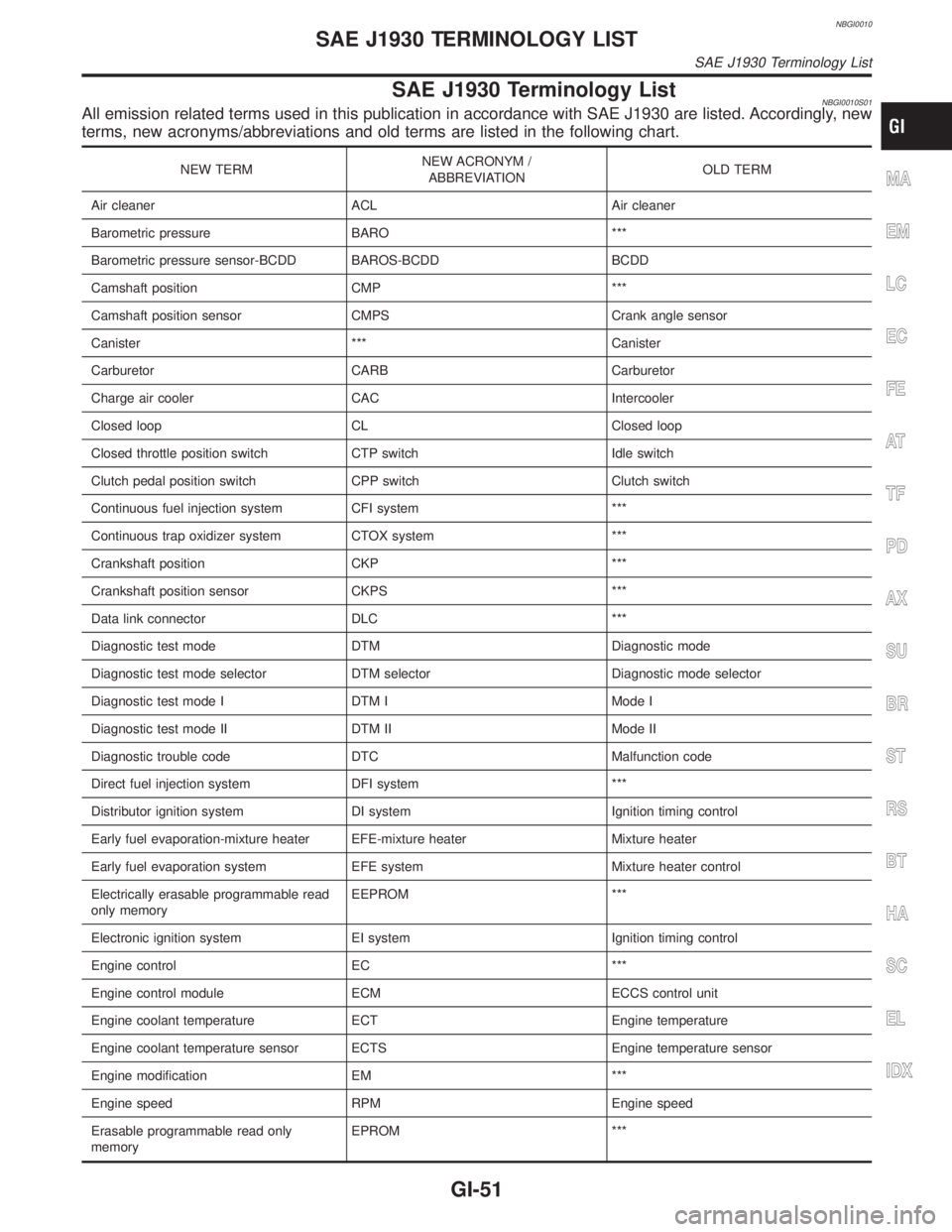
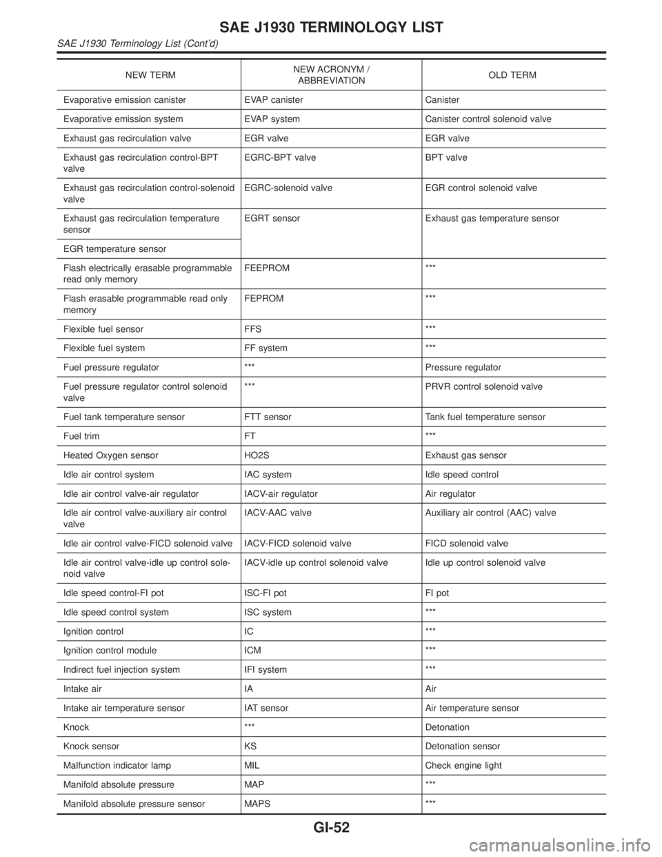
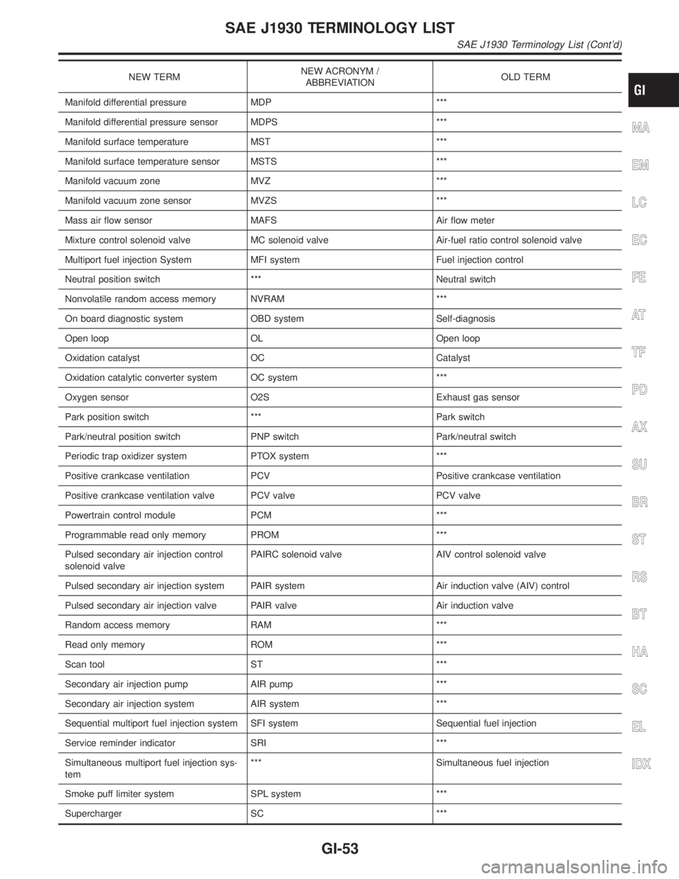
SAE J1930 Terminology ListNBGI0010S01All emission related terms used in this publication in accordance with SAE J1930 are listed. Accordingly, new
terms, new acronyms/abbreviations and old terms are listed in the following chart.
NEW TERMNEW ACRONYM /
ABBREVIATIONOLD TERM
Air cleaner ACL Air cleaner
Barometric pressure BARO ***
Barometric pressure sensor-BCDD BAROS-BCDD BCDD
Camshaft position CMP ***
Camshaft position sensor CMPS Crank angle sensor
Canister *** Canister
Carburetor CARB Carburetor
Charge air cooler CAC Intercooler
Closed loop CL Closed loop
Closed throttle position switch CTP switch Idle switch
Clutch pedal position switch CPP switch Clutch switch
Continuous fuel injection system CFI system ***
Continuous trap oxidizer system CTOX system ***
Crankshaft position CKP ***
Crankshaft position sensor CKPS ***
Data link connector DLC ***
Diagnostic test mode DTM Diagnostic mode
Diagnostic test mode selector DTM selector Diagnostic mode selector
Diagnostic test mode I DTM I Mode I
Diagnostic test mode II DTM II Mode II
Diagnostic trouble code DTC Malfunction code
Direct fuel injection system DFI system ***
Distributor ignition system DI system Ignition timing control
Early fuel evaporation-mixture heater EFE-mixture heater Mixture heater
Early fuel evaporation system EFE system Mixture heater control
Electrically erasable programmable read
only memoryEEPROM ***
Electronic ignition system EI system Ignition timing control
Engine control EC ***
Engine control module ECM ECCS control unit
Engine coolant temperature ECT Engine temperature
Engine coolant temperature sensor ECTS Engine temperature sensor
Engine modification EM ***
Engine speed RPM Engine speed
Erasable programmable read only
memoryEPROM ***MA
EM
LC
EC
FE
AT
TF
PD
AX
SU
BR
ST
RS
BT
HA
SC
EL
IDX
SAE J1930 TERMINOLOGY LIST
SAE J1930 Terminology List
GI-51
Page 1797 of 2395
NEW TERMNEW ACRONYM /
ABBREVIATIONOLD TERM
Evaporative emission canister EVAP canister Canister
Evaporative emission system EVAP system Canister control solenoid valve
Exhaust gas recirculation valve EGR valve EGR valve
Exhaust gas recirculation control-BPT
valveEGRC-BPT valve BPT valve
Exhaust gas recirculation control-solenoid
valveEGRC-solenoid valve EGR control solenoid valve
Exhaust gas recirculation temperature
sensorEGRT sensor Exhaust gas temperature sensor
EGR temperature sensor
Flash electrically erasable programmable
read only memoryFEEPROM ***
Flash erasable programmable read only
memoryFEPROM ***
Flexible fuel sensor FFS ***
Flexible fuel system FF system ***
Fuel pressure regulator *** Pressure regulator
Fuel pressure regulator control solenoid
valve*** PRVR control solenoid valve
Fuel tank temperature sensor FTT sensor Tank fuel temperature sensor
Fuel trim FT ***
Heated Oxygen sensor HO2S Exhaust gas sensor
Idle air control system IAC system Idle speed control
Idle air control valve-air regulator IACV-air regulator Air regulator
Idle air control valve-auxiliary air control
valveIACV-AAC valve Auxiliary air control (AAC) valve
Idle air control valve-FICD solenoid valve IACV-FICD solenoid valve FICD solenoid valve
Idle air control valve-idle up control sole-
noid valveIACV-idle up control solenoid valve Idle up control solenoid valve
Idle speed control-FI pot ISC-FI pot FI pot
Idle speed control system ISC system ***
Ignition control IC ***
Ignition control module ICM ***
Indirect fuel injection system IFI system ***
Intake air IA Air
Intake air temperature sensor IAT sensor Air temperature sensor
Knock *** Detonation
Knock sensor KS Detonation sensor
Malfunction indicator lamp MIL Check engine light
Manifold absolute pressure MAP ***
Manifold absolute pressure sensor MAPS ***
SAE J1930 TERMINOLOGY LIST
SAE J1930 Terminology List (Cont'd)
GI-52
Page 1798 of 2395
NEW TERMNEW ACRONYM /
ABBREVIATIONOLD TERM
Manifold differential pressure MDP ***
Manifold differential pressure sensor MDPS ***
Manifold surface temperature MST ***
Manifold surface temperature sensor MSTS ***
Manifold vacuum zone MVZ ***
Manifold vacuum zone sensor MVZS ***
Mass air flow sensor MAFS Air flow meter
Mixture control solenoid valve MC solenoid valve Air-fuel ratio control solenoid valve
Multiport fuel injection System MFI system Fuel injection control
Neutral position switch *** Neutral switch
Nonvolatile random access memory NVRAM ***
On board diagnostic system OBD system Self-diagnosis
Open loop OL Open loop
Oxidation catalyst OC Catalyst
Oxidation catalytic converter system OC system ***
Oxygen sensor O2S Exhaust gas sensor
Park position switch *** Park switch
Park/neutral position switch PNP switch Park/neutral switch
Periodic trap oxidizer system PTOX system ***
Positive crankcase ventilation PCV Positive crankcase ventilation
Positive crankcase ventilation valve PCV valve PCV valve
Powertrain control module PCM ***
Programmable read only memory PROM ***
Pulsed secondary air injection control
solenoid valvePAIRC solenoid valve AIV control solenoid valve
Pulsed secondary air injection system PAIR system Air induction valve (AIV) control
Pulsed secondary air injection valve PAIR valve Air induction valve
Random access memory RAM ***
Read only memory ROM ***
Scan tool ST ***
Secondary air injection pump AIR pump ***
Secondary air injection system AIR system ***
Sequential multiport fuel injection system SFI system Sequential fuel injection
Service reminder indicator SRI ***
Simultaneous multiport fuel injection sys-
tem*** Simultaneous fuel injection
Smoke puff limiter system SPL system ***
Supercharger SC ***
MA
EM
LC
EC
FE
AT
TF
PD
AX
SU
BR
ST
RS
BT
HA
SC
EL
IDX
SAE J1930 TERMINOLOGY LIST
SAE J1930 Terminology List (Cont'd)
GI-53
Page 1963 of 2395
E
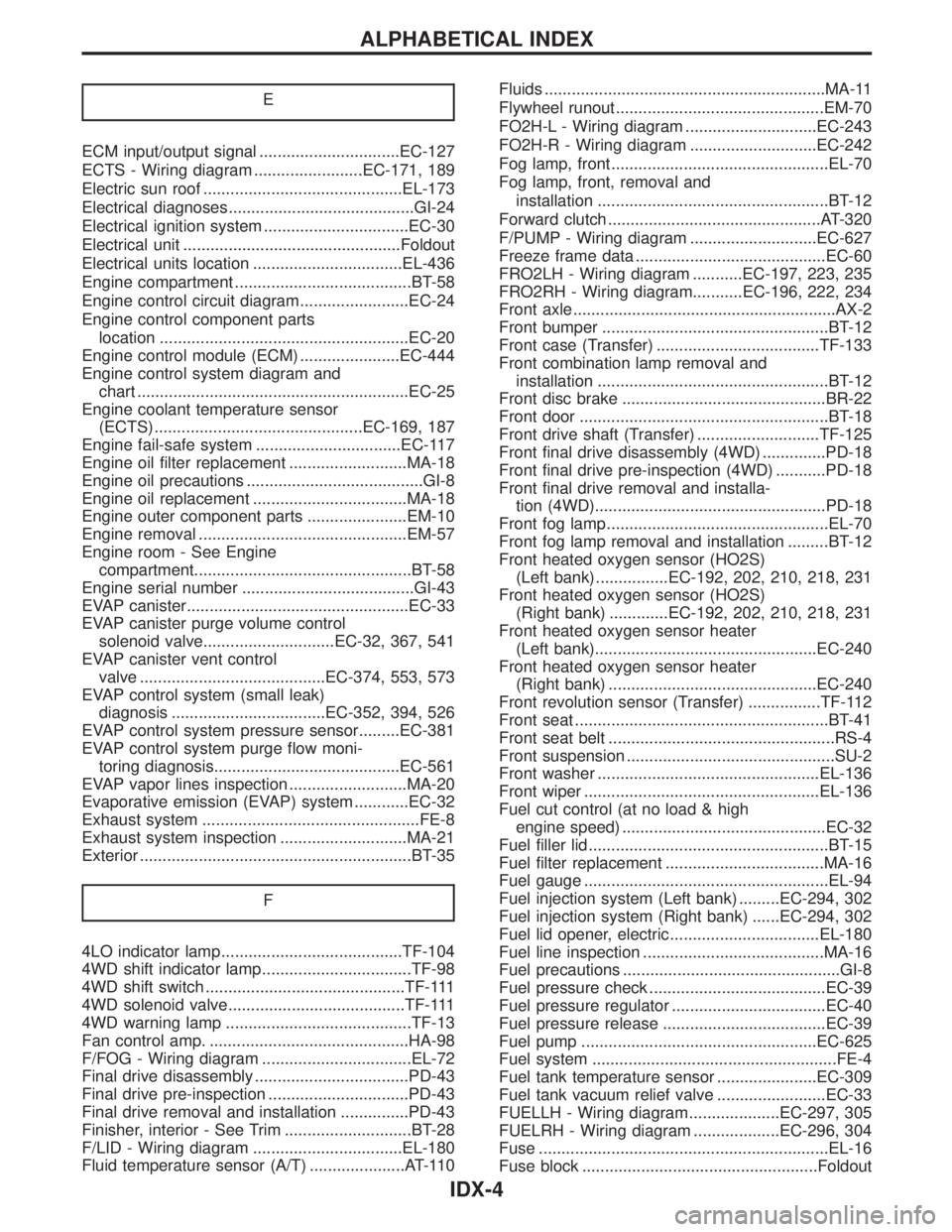
ECM input/output signal ...............................EC-127
ECTS - Wiring diagram ........................EC-171, 189
Electric sun roof ............................................EL-173
Electrical diagnoses.........................................GI-24
Electrical ignition system ................................EC-30
Electrical unit ................................................Foldout
Electrical units location .................................EL-436
Engine compartment .......................................BT-58
Engine control circuit diagram........................EC-24
Engine control component parts
location .......................................................EC-20
Engine control module (ECM) ......................EC-444
Engine control system diagram and
chart ............................................................EC-25
Engine coolant temperature sensor
(ECTS) ..............................................EC-169, 187
Engine fail-safe system ................................EC-117
Engine oil filter replacement ..........................MA-18
Engine oil precautions .......................................GI-8
Engine oil replacement ..................................MA-18
Engine outer component parts ......................EM-10
Engine removal ..............................................EM-57
Engine room - See Engine
compartment................................................BT-58
Engine serial number ......................................GI-43
EVAP canister.................................................EC-33
EVAP canister purge volume control
solenoid valve.............................EC-32, 367, 541
EVAP canister vent control
valve .........................................EC-374, 553, 573
EVAP control system (small leak)
diagnosis ..................................EC-352, 394, 526
EVAP control system pressure sensor.........EC-381
EVAP control system purge flow moni-
toring diagnosis.........................................EC-561
EVAP vapor lines inspection ..........................MA-20
Evaporative emission (EVAP) system ............EC-32
Exhaust system ................................................FE-8
Exhaust system inspection ............................MA-21
Exterior ............................................................BT-35
F
4LO indicator lamp........................................TF-104
4WD shift indicator lamp.................................TF-98
4WD shift switch ............................................TF-111
4WD solenoid valve.......................................TF-111
4WD warning lamp .........................................TF-13
Fan control amp. ............................................HA-98
F/FOG - Wiring diagram .................................EL-72
Final drive disassembly ..................................PD-43
Final drive pre-inspection ...............................PD-43
Final drive removal and installation ...............PD-43
Finisher, interior - See Trim ............................BT-28
F/LID - Wiring diagram .................................EL-180
Fluid temperature sensor (A/T) .....................AT-110Fluids ..............................................................MA-11
Flywheel runout..............................................EM-70
FO2H-L - Wiring diagram .............................EC-243
FO2H-R - Wiring diagram ............................EC-242
Fog lamp, front................................................EL-70
Fog lamp, front, removal and
installation ...................................................BT-12
Forward clutch ...............................................AT-320
F/PUMP - Wiring diagram ............................EC-627
Freeze frame data ..........................................EC-60
FRO2LH - Wiring diagram ...........EC-197, 223, 235
FRO2RH - Wiring diagram...........EC-196, 222, 234
Front axle..........................................................AX-2
Front bumper ..................................................BT-12
Front case (Transfer) ....................................TF-133
Front combination lamp removal and
installation ...................................................BT-12
Front disc brake .............................................BR-22
Front door .......................................................BT-18
Front drive shaft (Transfer) ...........................TF-125
Front final drive disassembly (4WD) ..............PD-18
Front final drive pre-inspection (4WD) ...........PD-18
Front final drive removal and installa-
tion (4WD)...................................................PD-18
Front fog lamp.................................................EL-70
Front fog lamp removal and installation .........BT-12
Front heated oxygen sensor (HO2S)
(Left bank) ................EC-192, 202, 210, 218, 231
Front heated oxygen sensor (HO2S)
(Right bank) .............EC-192, 202, 210, 218, 231
Front heated oxygen sensor heater
(Left bank).................................................EC-240
Front heated oxygen sensor heater
(Right bank) ..............................................EC-240
Front revolution sensor (Transfer) ................TF-112
Front seat ........................................................BT-41
Front seat belt ..................................................RS-4
Front suspension ..............................................SU-2
Front washer .................................................EL-136
Front wiper ....................................................EL-136
Fuel cut control (at no load & high
engine speed) .............................................EC-32
Fuel filler lid.....................................................BT-15
Fuel filter replacement ...................................MA-16
Fuel gauge ......................................................EL-94
Fuel injection system (Left bank) .........EC-294, 302
Fuel injection system (Right bank) ......EC-294, 302
Fuel lid opener, electric.................................EL-180
Fuel line inspection ........................................MA-16
Fuel precautions ................................................GI-8
Fuel pressure check .......................................EC-39
Fuel pressure regulator ..................................EC-40
Fuel pressure release ....................................EC-39
Fuel pump ....................................................EC-625
Fuel system ......................................................FE-4
Fuel tank temperature sensor ......................EC-309
Fuel tank vacuum relief valve ........................EC-33
FUELLH - Wiring diagram....................EC-297, 305
FUELRH - Wiring diagram ...................EC-296, 304
Fuse ................................................................EL-16
Fuse block ....................................................Foldout
ALPHABETICAL INDEX
IDX-4
Page 1965 of 2395
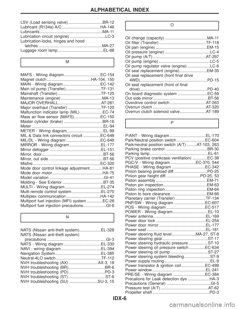
LSV (Load sensing valve) ..............................BR-12
Lubricant (R134a) A/C..................................HA-146
Lubricants .......................................................MA-11
Lubrication circuit (engine) ...............................LC-3
Lubrication-locks, hinges and hood
latches ........................................................MA-27
Luggage room lamp ........................................EL-88
M
MAFS - Wiring diagram................................EC-154
Magnet clutch .......................................HA-104, 150
MAIN - Wiring diagram.................................EC-142
Main oil pump (Transfer)...............................TF-131
Mainshaft (Transfer) ......................................TF-125
Maintenance (engine) ....................................MA-13
MAJOR OVERHALL......................................AT-281
Major overhaul (Transfer) .............................TF-120
Malfunction indicator lamp (MIL) ....................EC-74
Mass air flow sensor (MAFS) .......................EC-150
Master cylinder (brake) ..................................BR-16
Meter ...............................................................EL-94
METER - Wiring diagram................................EL-99
MIL & Data link connectors circuit ...............EC-648
MIL/DL - Wiring diagram ..............................EC-648
MIRROR - Wiring diagram............................EL-177
Mirror defogger .............................................EL-151
Mirror, door......................................................BT-56
Mirror, out side ................................................BT-56
Misfire ...........................................................EC-320
Mode door control linkage adjustment ...........HA-81
Mode door motor ............................................HA-75
Model variation ................................................GI-41
Molding - See Exterior ....................................BT-35
MULTI - Wiring diagram ................................EL-274
Multi-remote control system..........................EL-270
Multiplex communication ..............................HA-142
Multiport fuel injection (MFI) system ..............EC-28
Multiport fuel injection precautions ....................GI-6
N
NATS (Nissan anti-theft system)...................EL-328
NATS (Nissan anti-theft system)
precautions ....................................................GI-3
NATS - Wiring diagram .................................EL-330
NAVI - wiring diagram ...................................EL-394
Navigation System ........................................EL-385
Neutral-4LO switch ........................................TF-112
NVH troubleshooting (AX) ..........................AX-3, 18
NVH troubleshooting (BR)................................BR-6
NVH troubleshooting (PD)................................PD-3
NVH troubleshooting (ST).................................ST-6
NVH troubleshooting (SU) .........................SU-3, 15O
Oil change (capacity) .....................................MA-11
Oil filter (Transfer) .........................................TF-118
Oil pan (engine) .............................................EM-15
Oil pressure (engine) ........................................LC-4
Oil pump (A/T) ...............................................AT-297
Oil pump (engine) .............................................LC-5
Oil pump regulator valve (engine) ....................LC-6
Oil seal replacement (engine)........................EM-35
Oil seal replacement (front final drive
4WD) ...........................................................PD-15
Oil seal replacement (front of final
drive) ...........................................................PD-40
On board diagnostic system ..........................EC-59
Out side mirror ................................................BT-56
Overdrive control switch ................................AT-263
Overrun clutch ...............................................AT-320
Overrun clutch solenoid valve .......................AT-189
P
P/ANT - Wiring diagram ................................EL-170
Park/Neutral position switch .........................EC-604
Park/neutral position switch (A/T) .........AT-103, 263
Parking brake control .....................................BR-30
Parking lamp ...................................................EL-61
PCV (positive crankcase ventilation) .............EC-38
PGC/V - Wiring diagram ......................EC-370, 544
PHASE - Wiring diagram .............................EC-342
Pinion bearing preload diff. ............................PD-25
Pinion gear height diff. .............................PD-25, 53
Piston assembly .............................................EM-71
Piston pin inspection ......................................EM-63
Piston ring inspection.....................................EM-64
Piston to bore clearance ................................EM-66
Planetary carrier (Transfer) ...........................TF-134
PNP/SW - Wiring diagram ...........................EC-607
POS - Wiring diagram ..................................EC-517
POWER - Wiring diagram...............................EL-10
Power antenna ..............................................EL-169
Power door lock ............................................EL-254
Power door mirror .........................................EL-177
Power seat ....................................................EL-181
Power steering fluid level .....................MA-27, ST-8
Power steering gear........................................ST-17
Power steering hydraulic pressure .................ST-10
Power steering oil pressure switch ..............EC-634
Power steering oil pump .................................ST-27
Power steering system bleeding.......................ST-9
Power supply routing ........................................EL-9
Power transistor & ignition coil.....................EC-499
Power window ...............................................EL-241
PRE/SE - Wiring diagram ............................EC-384
Precations for Leak detection dye ...................HA-3
Precautions (General) .......................................GI-5
Pressure test (A/T) ..........................................AT-62
Propeller shaft ..................................................PD-3
ALPHABETICAL INDEX
IDX-6
Page 1986 of 2395
3. Then check if valve closes at 5ÉC (9ÉF) below valve opening
temperature.
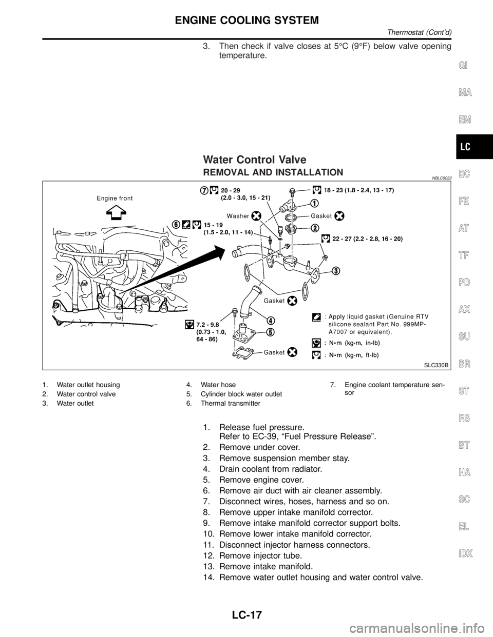
Water Control Valve
REMOVAL AND INSTALLATIONNBLC0032
SLC330B
1. Water outlet housing
2. Water control valve
3. Water outlet4. Water hose
5. Cylinder block water outlet
6. Thermal transmitter7. Engine coolant temperature sen-
sor
1. Release fuel pressure.
Refer to EC-39, ªFuel Pressure Releaseº.
2. Remove under cover.
3. Remove suspension member stay.
4. Drain coolant from radiator.
5. Remove engine cover.
6. Remove air duct with air cleaner assembly.
7. Disconnect wires, hoses, harness and so on.
8. Remove upper intake manifold corrector.
9. Remove intake manifold corrector support bolts.
10. Remove lower intake manifold corrector.
11. Disconnect injector harness connectors.
12. Remove injector tube.
13. Remove intake manifold.
14. Remove water outlet housing and water control valve.
GI
MA
EM
EC
FE
AT
TF
PD
AX
SU
BR
ST
RS
BT
HA
SC
EL
IDX
ENGINE COOLING SYSTEM
Thermostat (Cont'd)
LC-17
Page 2011 of 2395
steps 4 through 8 until coolant level no longer drops.
IClean excess coolant from engine.
ÐFLUSHING COOLING SYSTEMÐNBMA0011S031. Open air relief plug.
2. Fill radiator with water until water spills from the air relief holes,
then close air relief plugs. Fill radiator and reservoir tank with
water and reinstall radiator cap.
3. Run engine and warm it up to normal operating temperature.
4. Rev engine two or three times under no-load.
5. Stop engine and wait until it cools down.
6. Drain water.
7. Repeat steps 1 through 6 until clear water begins to drain from
radiator.
SMA803A
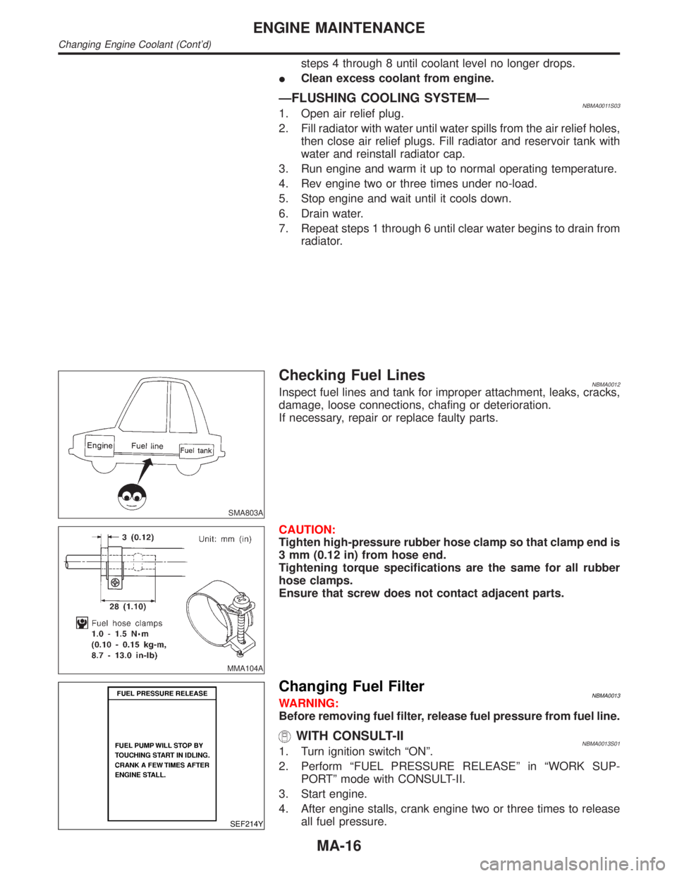
Checking Fuel LinesNBMA0012Inspect fuel lines and tank for improper attachment, leaks, cracks,
damage, loose connections, chafing or deterioration.
If necessary, repair or replace faulty parts.
MMA104A
CAUTION:
Tighten high-pressure rubber hose clamp so that clamp end is
3 mm (0.12 in) from hose end.
Tightening torque specifications are the same for all rubber
hose clamps.
Ensure that screw does not contact adjacent parts.
SEF214Y
Changing Fuel FilterNBMA0013WARNING:
Before removing fuel filter, release fuel pressure from fuel line.
WITH CONSULT-IINBMA0013S011. Turn ignition switch ªONº.
2. Perform ªFUEL PRESSURE RELEASEº in ªWORK SUP-
PORTº mode with CONSULT-II.
3. Start engine.
4. After engine stalls, crank engine two or three times to release
all fuel pressure.
ENGINE MAINTENANCE
Changing Engine Coolant (Cont'd)
MA-16