Page 1650 of 2395
Tool number
(Kent-Moore No.)
Tool nameDescription
Valve guide reamer
NT016
Reaming valve guide 1 or hole for oversize valve
guide 2
Intake & Exhaust:
d
1= 6.0 mm (0.236 in) dia.
d
2= 10.2 mm (0.402 in) dia.
(J-43897-18)
(J-43897-12)
Oxygen sensor thread
cleaner
AEM488
Reconditioning the exhaust system threads before
installing a new oxygen sensor (Use with anti-seize
lubricant shown below.)
a = J-43897-18 (18 mm dia.) for zirconia oxygen
sensor
b = J-43897-12 (12 mm dia.) for titania oxygen
sensor
Anti-seize lubricant
(Permatex 133AR or
equivalent meeting MIL
specification MIL-A-
907)
AEM489
Lubricating oxygen sensor thread cleaning tool
when reconditioning exhaust system threads
GI
MA
LC
EC
FE
AT
TF
PD
AX
SU
BR
ST
RS
BT
HA
SC
EL
IDX
PREPARATION
Commercial Service Tools (Cont'd)
EM-7
Page 1652 of 2395

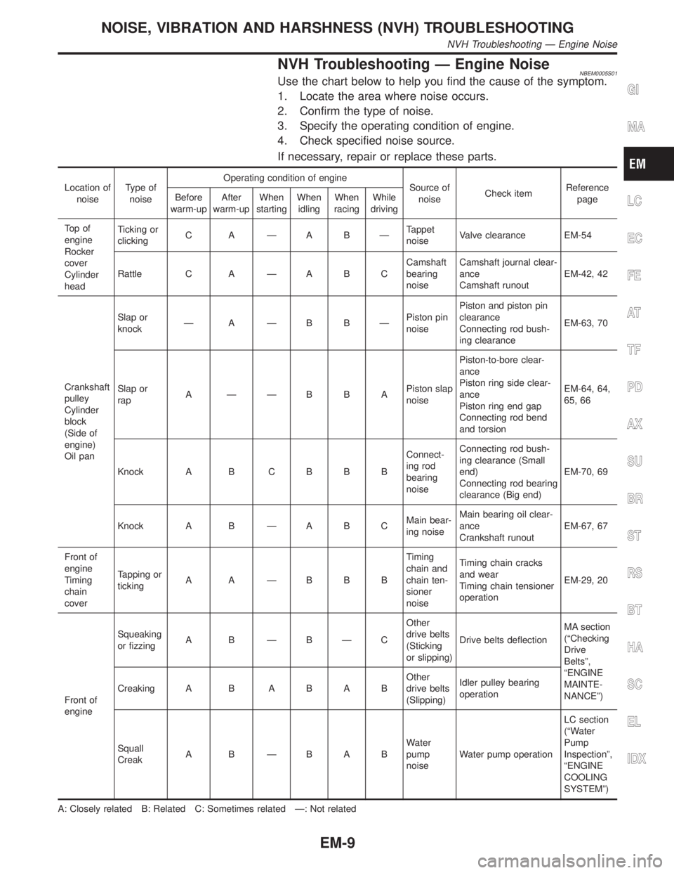
NVH Troubleshooting Ð Engine NoiseNBEM0005S01Use the chart below to help you find the cause of the symptom.
1. Locate the area where noise occurs.
2. Confirm the type of noise.
3. Specify the operating condition of engine.
4. Check specified noise source.
If necessary, repair or replace these parts.
Location of
noiseType of
noiseOperating condition of engine
Source of
noiseCheck itemReference
page Before
warm-upAfter
warm-upWhen
startingWhen
idlingWhen
racingWhile
driving
To p o f
engine
Rocker
cover
Cylinder
headTicking or
clickingC A ÐA BÐTappet
noiseValve clearance EM-54
Rattle C A Ð A B CCamshaft
bearing
noiseCamshaft journal clear-
ance
Camshaft runoutEM-42, 42
Crankshaft
pulley
Cylinder
block
(Side of
engine)
Oil panSlap or
knockÐ A ÐB BÐPiston pin
noisePiston and piston pin
clearance
Connecting rod bush-
ing clearanceEM-63, 70
Slap or
rapA ÐÐBBAPiston slap
noisePiston-to-bore clear-
ance
Piston ring side clear-
ance
Piston ring end gap
Connecting rod bend
and torsionEM-64, 64,
65, 66
Knock A B C B B BConnect-
ing rod
bearing
noiseConnecting rod bush-
ing clearance (Small
end)
Connecting rod bearing
clearance (Big end)EM-70, 69
Knock A B Ð A B CMain bear-
ing noiseMain bearing oil clear-
ance
Crankshaft runoutEM-67, 67
Front of
engine
Timing
chain
coverTapping or
tickingA A ÐBBBTiming
chain and
chain ten-
sioner
noiseTiming chain cracks
and wear
Timing chain tensioner
operationEM-29, 20
Front of
engineSqueaking
or fizzingA B ÐBÐCOther
drive belts
(Sticking
or slipping)Drive belts deflectionMA section
(ªChecking
Drive
Beltsº,
ªENGINE
MAINTE-
NANCEº) Creaking A BABABOther
drive belts
(Slipping)Idler pulley bearing
operation
Squall
CreakA B ÐBABWater
pump
noiseWater pump operationLC section
(ªWater
Pump
Inspectionº,
ªENGINE
COOLING
SYSTEMº)
A: Closely related B: Related C: Sometimes related Ð: Not related
GI
MA
LC
EC
FE
AT
TF
PD
AX
SU
BR
ST
RS
BT
HA
SC
EL
IDX
NOISE, VIBRATION AND HARSHNESS (NVH) TROUBLESHOOTING
NVH Troubleshooting Ð Engine Noise
EM-9
Page 1658 of 2395
ComponentsNBEM0008
SEM583G
RemovalNBEM0009WARNING:
IPlace vehicle on a flat and solid surface.
IYou should not remove oil pan until exhaust system and
cooling system have completely cooled off.
Otherwise, you may burn yourself and/or fire may break
out in the fuel line.
IWhen removing front engine mounting nuts, lift up slightly
engine for safety work.
CAUTION:
When removing the aluminum oil pan from engine, first
remove the crankshaft position sensors (POS and REF) from
the assembly.
Be careful not to damage sensor edges and signal plate teeth.
1. Remove front RH and LH wheels.
2. Remove battery.
3. Remove oil level gauge.
4. Remove engine undercover.
5. Remove suspension member stay.
6. Drain engine coolant from radiator drain plug.
7. Disconnect A/T oil cooler hoses.
8. Drain engine oil.
GI
MA
LC
EC
FE
AT
TF
PD
AX
SU
BR
ST
RS
BT
HA
SC
EL
IDX
OIL PAN
Components
EM-15
Page 1700 of 2395

Removal and InstallationNBEM0042WARNING:
ISituate vehicle on a flat and solid surface.
IPlace chocks at front and back of rear wheels.
IDo not remove engine until exhaust system has com-
pletely cooled off. Otherwise, you may burn yourself
and/or fire may break out in fuel line.
IFor safety during subsequent steps, the tension of wires
should be slackened against the engine.
IBefore disconnecting fuel hose, release fuel pressure
from fuel line.
Refer to EC-39, ªFuel Pressure Releaseº.
IBefore removing front axle from transmission, place
safety stands under designated front supporting points.
Refer to GI section for lifting points and towing.
IBe sure to hoist engine and transmission in a safe man-
ner.
IFor engines not equipped with engine slingers, attach
proper slingers and bolts described in PARTS CATALOG.
CAUTION:
IWhen lifting engine, be careful not to strike adjacent parts,
especially accelerator wire casing, brake lines, and brake
master cylinder.
IIn hoisting the engine, always use engine slingers in a
safe manner.
IBefore separating engine and transmission, remove
crankshaft position sensor (POS) from the assembly.
IAlways take extra care not to damage edge of crankshaft
position sensor (POS), or ring gear teeth.GI
MA
LC
EC
FE
AT
TF
PD
AX
SU
BR
ST
RS
BT
HA
SC
EL
IDX
ENGINE ASSEMBLY
Removal and Installation
EM-57
Page 1730 of 2395
ACCELERATOR CONTROL, FUEL &
EXHAUST SYSTEMS
SECTION
FE
CONTENTS
PREPARATION...............................................................2
Special Service Tool ....................................................2
Commercial Service Tools ...........................................2
ACCELERATOR CONTROL SYSTEM...........................3
Removal and Installation .............................................3
Adjusting Accelerator Wire ..........................................3FUEL SYSTEM................................................................4
Removal and Installation .............................................4
FUEL TANK...............................................................5
FUEL PUMP AND GAUGE.........................................6
EXHAUST SYSTEM........................................................8
Removal and Installation .............................................8
GI
MA
EM
LC
EC
AT
TF
PD
AX
SU
BR
ST
RS
BT
HA
SC
EL
IDX
Page 1731 of 2395
Special Service ToolNBFE0001The actual shapes of Kent-Moore tools may differ from those of special service tools illustrated here.
Tool number
(Kent-Moore No.)
Tool nameDescription
KV10114400 (J38365)
Heated oxygen sensor
wrench
NT636
Loosening or tightening rear heated oxy-
gen sensor (For right bank)
a: 22 mm (0.87 in)
Commercial Service ToolsNBFE0007
Tool number
(Kent-Moore No.)
Tool nameDescription
Oxygen sensor thread
cleaner
(J-43897-18)
(J-43897-12)
NT778
Reconditioning the exhaust system
threads before installing a new oxygen
sensor. Use with anti-seize lubricant
shown below.
a: J-43897-18 (18 mm dia.) for Zirconia
Oxygen Sensor
b: J-43897-12 (12 mm dia.) for Titania
Oxygen Sensor
Anti-seize lubricant (Per-
matex
TM133AR or
equivalent meeting MIL
specification MIL-A-907)
NT779
Lubricating oxygen sensor thread cleaning
tool when reconditioning exhaust system
threads.
PREPARATION
Special Service Tool
FE-2
Page 1732 of 2395

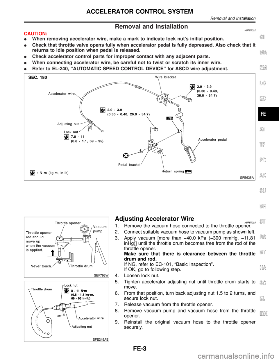
Removal and InstallationNBFE0002CAUTION:
IWhen removing accelerator wire, make a mark to indicate lock nut's initial position.
ICheck that throttle valve opens fully when accelerator pedal is fully depressed. Also check that it
returns to idle position when pedal is released.
ICheck accelerator control parts for improper contact with any adjacent parts.
IWhen connecting accelerator wire, be careful not to twist or scratch its inner wire.
IRefer to EL-240, ªAUTOMATIC SPEED CONTROL DEVICEº for ASCD wire adjustment.
SFE635A
SEF793W
SFE249AE
Adjusting Accelerator WireNBFE00031. Remove the vacuum hose connected to the throttle opener.
2. Connect suitable vacuum hose to vacuum pump as shown left.
3. Apply vacuum [more than þ40.0 kPa (þ300 mmHg, þ11.81
inHg)] until the throttle drum becomes free from the rod of the
throttle opener.
Make sure that there is clearance between the throttle
drum and rod.
If NG, refer to EC-101, ªBasic Inspectionº.
If OK, go to following step.
4. Loosen lock nut.
5. Tighten accelerator adjusting nut until throttle drum starts to
move.
6. From that position, turn back adjusting nut 1.5 to 2 turns, and
secure lock nut.
7. Release vacuum from the throttle opener.
8. Remove vacuum pump and vacuum hose from the throttle
opener.
9. Reinstall the original vacuum hose to the throttle opener
securely.
GI
MA
EM
LC
EC
AT
TF
PD
AX
SU
BR
ST
RS
BT
HA
SC
EL
IDX
ACCELERATOR CONTROL SYSTEM
Removal and Installation
FE-3
Page 1733 of 2395

Removal and InstallationNBFE0004WARNING:
When replacing fuel line parts, be sure to observe the follow-
ing:
IPut a ªCAUTION: INFLAMMABLEº sign in workshop.
IDo not smoke while servicing fuel system. Keep open
flames and sparks away from work area.
IBe sure to furnish the workshop with a CO
2fire extin-
guisher.
CAUTION:
IBefore removing fuel line parts, carry out the following
procedures:
a) Put drained fuel in an explosion-proof container and put
lid on securely.
b) Release fuel pressure from fuel line. Refer to MA-16,
ªChanging Fuel Filterº.
c) Disconnect battery ground cable.
IAlways replace O-ring with new ones.
IDo not kink or twist hose and tube when they are installed.
IDo not tighten hose clamps excessively to avoid damag-
ing hoses.
IWhen installing fuel check valve, be careful of its desig-
nated direction. Refer to EC-32, ªEVAPORATIVE EMIS-
SION SYSTEMº.
IAfter installation, run engine and check for fuel leaks at
connections.
FUEL SYSTEM
Removal and Installation
FE-4