Page 2200 of 2395
in high-pressure connector. Take care to install the proper
O-ring.
SST616C
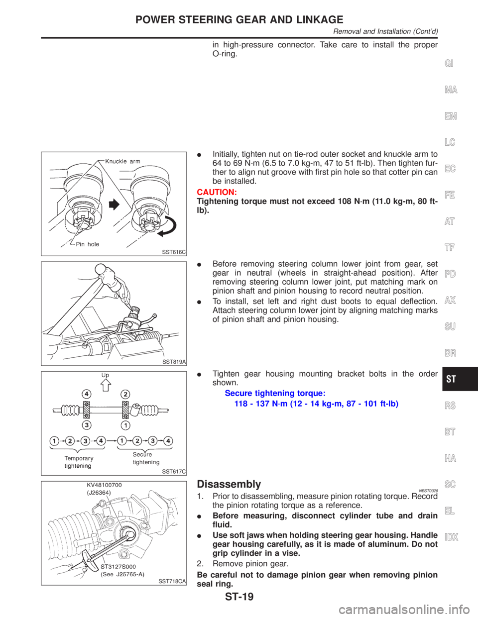
IInitially, tighten nut on tie-rod outer socket and knuckle arm to
64 to 69 N´m (6.5 to 7.0 kg-m, 47 to 51 ft-lb). Then tighten fur-
ther to align nut groove with first pin hole so that cotter pin can
be installed.
CAUTION:
Tightening torque must not exceed 108 N´m (11.0 kg-m, 80 ft-
lb).
SST819A
IBefore removing steering column lower joint from gear, set
gear in neutral (wheels in straight-ahead position). After
removing steering column lower joint, put matching mark on
pinion shaft and pinion housing to record neutral position.
ITo install, set left and right dust boots to equal deflection.
Attach steering column lower joint by aligning matching marks
of pinion shaft and pinion housing.
SST617C
ITighten gear housing mounting bracket bolts in the order
shown.
Secure tightening torque:
118 - 137 N´m (12 - 14 kg-m, 87 - 101 ft-lb)
SST718CA
DisassemblyNBST00281. Prior to disassembling, measure pinion rotating torque. Record
the pinion rotating torque as a reference.
IBefore measuring, disconnect cylinder tube and drain
fluid.
IUse soft jaws when holding steering gear housing. Handle
gear housing carefully, as it is made of aluminum. Do not
grip cylinder in a vise.
2. Remove pinion gear.
Be careful not to damage pinion gear when removing pinion
seal ring.
GI
MA
EM
LC
EC
FE
AT
TF
PD
AX
SU
BR
RS
BT
HA
SC
EL
IDX
POWER STEERING GEAR AND LINKAGE
Removal and Installation (Cont'd)
ST-19
Page 2220 of 2395
SMA525A
On-vehicle Service
FRONT SUSPENSION PARTSNBSU0005Check front axle and front suspension parts for excessive play,
cracks, wear and other damage.
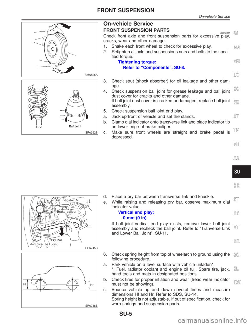
1. Shake each front wheel to check for excessive play.
2. Retighten all axle and suspensions nuts and bolts to the speci-
fied torque.
Tightening torque:
Refer to ªComponentsº, SU-8.
SFA392B
3. Check strut (shock absorber) for oil leakage and other dam-
age.
4. Check suspension ball joint for grease leakage and ball joint
dust cover for cracks and other damage.
If ball joint dust cover is cracked or damaged, replace ball joint
assembly.
5. Check suspension ball joint end play.
a. Jack up front of vehicle and set the stands.
b. Clamp dial indicator onto transverse link and place indicator tip
on lower edge of brake caliper.
c. Make sure front wheels are straight and brake pedal is
depressed.
SFA745B
d. Place a pry bar between transverse link and knuckle.
e. While raising and releasing pry bar, observe maximum dial
indicator value.
Vertical end play:
0mm(0in)
If ball joint vertical end play exists, remove lower ball joint
assembly and recheck the ball joint. Refer to ªTranverse Link
and Lower Ball Jointº, SU-11.
SFA746B
6. Check spring height from top of wheelarch to ground using the
following procedure.
a. Park vehicle on a level surface with vehicle unladen*.
*: Fuel, radiator coolant and engine oil full. Spare tire, jack,
hand tools and mats in designated positions.
b. Check tires for proper inflation and wear (tread wear indicator
must not be showing).
c. Bounce vehicle up and down several times and measure
dimensions Hf and Hr. Refer to SDS, SU-14.
Spring height is not adjustable. If out of specification, check for
worn springs and suspension parts.
GI
MA
EM
LC
EC
FE
AT
TF
PD
AX
BR
ST
RS
BT
HA
SC
EL
IDX
FRONT SUSPENSION
On-vehicle Service
SU-5
Page 2221 of 2395
SFA975B
FRONT WHEEL ALIGNMENTNBSU0006Before checking front wheel alignment, be sure to make a prelimi-
nary inspection (Unladen*).
*: Fuel, radiator coolant and engine oil full. Spare tire, jack, hand
tools and mats in designated positions.
Preliminary InspectionNBSU0006S011. Check tires for wear and improper inflation.
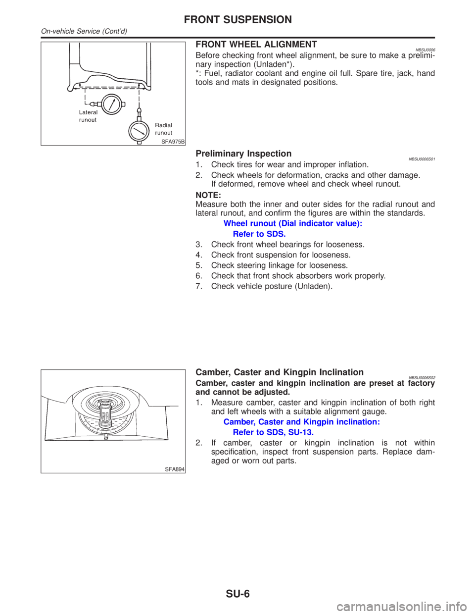
2. Check wheels for deformation, cracks and other damage.
If deformed, remove wheel and check wheel runout.
NOTE:
Measure both the inner and outer sides for the radial runout and
lateral runout, and confirm the figures are within the standards.
Wheel runout (Dial indicator value):
Refer to SDS.
3. Check front wheel bearings for looseness.
4. Check front suspension for looseness.
5. Check steering linkage for looseness.
6. Check that front shock absorbers work properly.
7. Check vehicle posture (Unladen).
SFA894
Camber, Caster and Kingpin InclinationNBSU0006S02Camber, caster and kingpin inclination are preset at factory
and cannot be adjusted.
1. Measure camber, caster and kingpin inclination of both right
and left wheels with a suitable alignment gauge.
Camber, Caster and Kingpin inclination:
Refer to SDS, SU-13.
2. If camber, caster or kingpin inclination is not within
specification, inspect front suspension parts. Replace dam-
aged or worn out parts.
FRONT SUSPENSION
On-vehicle Service (Cont'd)
SU-6
Page 2222 of 2395
SFA614B
SFA234AC
Toe-inNBSU0006S03Measure toe-in using the following procedure.
WARNING:
IAlways perform the following procedure on a flat surface.
IMake sure that no person is in front of the vehicle before
pushing it.
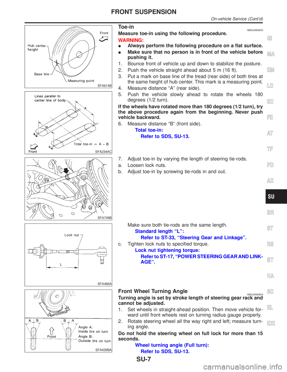
1. Bounce front of vehicle up and down to stabilize the posture.
2. Push the vehicle straight ahead about 5 m (16 ft).
3. Put a mark on base line of the tread (rear side) of both tires at
the same height of hub center. This mark is a measuring point.
4. Measure distance ªAº (rear side).
5. Push the vehicle slowly ahead to rotate the wheels 180
degrees (1/2 turn).
If the wheels have rotated more than 180 degrees (1/2 turn), try
the above procedure again from the beginning. Never push
vehicle backward.
6. Measure distance ªBº (front side).
Total toe-in:
Refer to SDS, SU-13.
SFA749B
7. Adjust toe-in by varying the length of steering tie-rods.
a. Loosen lock nuts.
b. Adjust toe-in by screwing tie-rods in and out.
SFA486A
Make sure both tie-rods are the same length.
Standard length ªLº:
Refer to ST-33, ªSteering Gear and Linkageº.
c. Tighten lock nuts to specified torque.
Lock nut tightening torque:
Refer to ST-17, ªPOWER STEERING GEAR AND LINK-
AGEº.
SFA439BA
Front Wheel Turning AngleNBSU0006S04Turning angle is set by stroke length of steering gear rack and
cannot be adjusted.
1. Set wheels in straight-ahead position. Then move vehicle for-
ward until front wheels rest on turning radius gauge properly.
2. Rotate steering wheel all the way right and left; measure turn-
ing angle.
Do not hold the steering wheel on full lock for more than 15
seconds.
Wheel turning angle (Full turn):
Refer to SDS, SU-13.
GI
MA
EM
LC
EC
FE
AT
TF
PD
AX
BR
ST
RS
BT
HA
SC
EL
IDX
FRONT SUSPENSION
On-vehicle Service (Cont'd)
SU-7
Page 2251 of 2395
2-4WD SHIFT SOLENOID VALVENBTF0067S03The 2-4WD shift solenoid valve operates to apply oil pressure to the wet, multiplate clutch, depending on the
drive mode. The driving force is transmitted to the front wheels through the clutch so the vehicle is set in the
4WD mode. Setting the vehicle in the 2WD mode requires no pressure buildup. In other words, pressure force
applied to the wet, multiplate clutch becomes zero.
LINE PRESSURE SWITCHNBTF0067S041. With the transfer system design, control of the oil pressure provides the transmission of drive torque to
the front wheels. The main pressure to control the oil pressure is referred to as the line pressure.
The line pressure switch determines whether or not adequate line pressure has built up under different
operating conditions.
2. The line pressure switch turns ON when line pressure is produced.
3. The line pressure switch senses line pressure abnormalities and turns the 4WD warning lamp ON.
ALL-MODE 4WD SYSTEM
Description of Electrical Parts (Cont'd)
TF-16
Page 2342 of 2395
Symptom 7. 4WD Shift Indicator Lamp Repeats
Flickering
=NBTF0035SYMPTOM: 4WD shift indicator lamp keeps flickering.
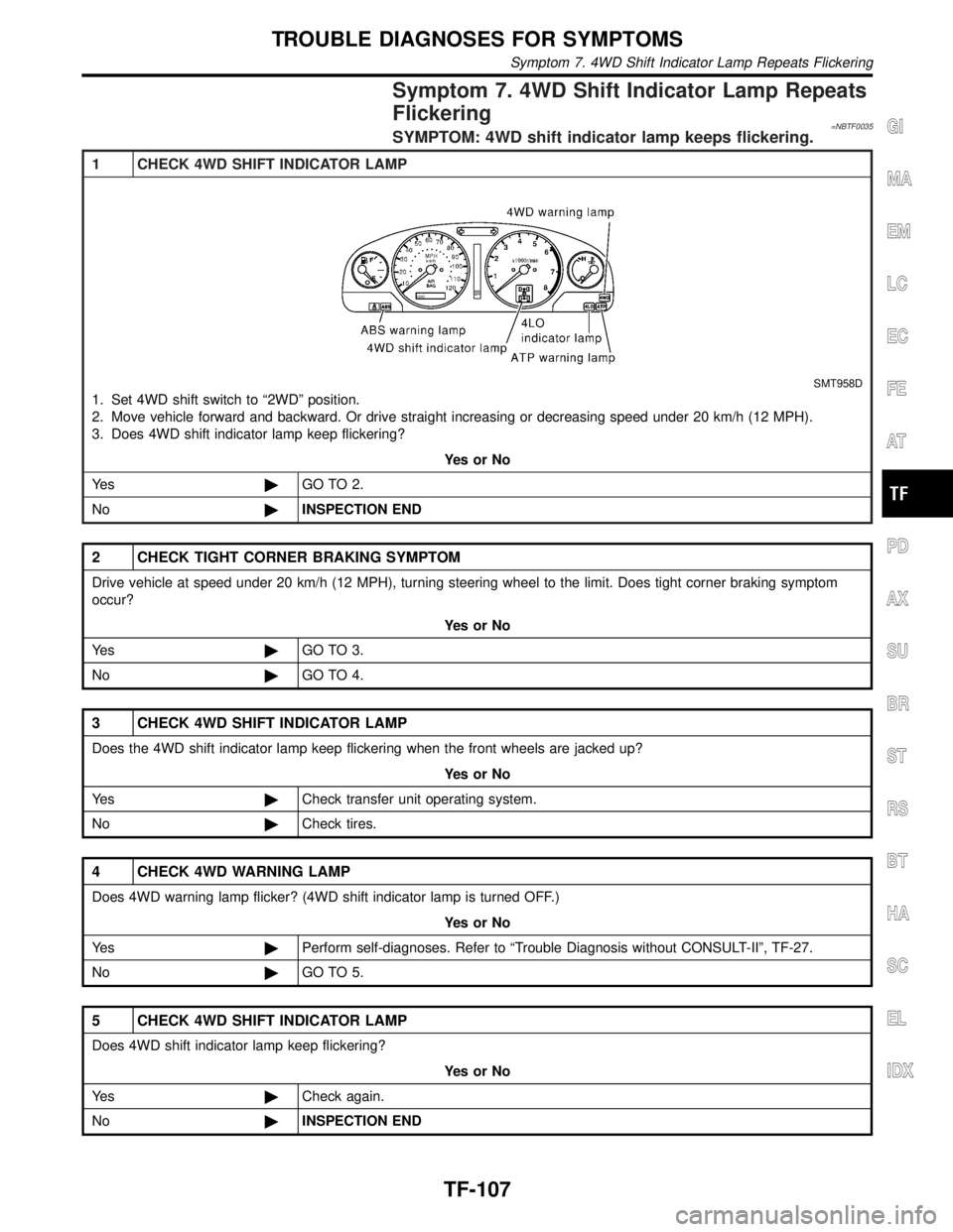
1 CHECK 4WD SHIFT INDICATOR LAMP
SMT958D
1. Set 4WD shift switch to ª2WDº position.
2. Move vehicle forward and backward. Or drive straight increasing or decreasing speed under 20 km/h (12 MPH).
3. Does 4WD shift indicator lamp keep flickering?
YesorNo
Ye s©GO TO 2.
No©INSPECTION END
2 CHECK TIGHT CORNER BRAKING SYMPTOM
Drive vehicle at speed under 20 km/h (12 MPH), turning steering wheel to the limit. Does tight corner braking symptom
occur?
YesorNo
Ye s©GO TO 3.
No©GO TO 4.
3 CHECK 4WD SHIFT INDICATOR LAMP
Does the 4WD shift indicator lamp keep flickering when the front wheels are jacked up?
YesorNo
Ye s©Check transfer unit operating system.
No©Check tires.
4 CHECK 4WD WARNING LAMP
Does 4WD warning lamp flicker? (4WD shift indicator lamp is turned OFF.)
YesorNo
Ye s©Perform self-diagnoses. Refer to ªTrouble Diagnosis without CONSULT-IIº, TF-27.
No©GO TO 5.
5 CHECK 4WD SHIFT INDICATOR LAMP
Does 4WD shift indicator lamp keep flickering?
YesorNo
Ye s©Check again.
No©INSPECTION END
GI
MA
EM
LC
EC
FE
AT
PD
AX
SU
BR
ST
RS
BT
HA
SC
EL
IDX
TROUBLE DIAGNOSES FOR SYMPTOMS
Symptom 7. 4WD Shift Indicator Lamp Repeats Flickering
TF-107