Page 2107 of 2395
SBF814E
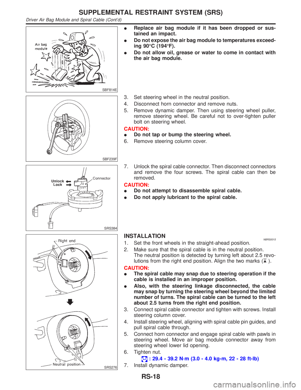
IReplace air bag module if it has been dropped or sus-
tained an impact.
IDo not expose the air bag module to temperatures exceed-
ing 90ÉC (194ÉF).
IDo not allow oil, grease or water to come in contact with
the air bag module.
SBF239F
3. Set steering wheel in the neutral position.
4. Disconnect horn connector and remove nuts.
5. Remove dynamic damper. Then using steering wheel puller,
remove steering wheel. Be careful not to over-tighten puller
bolt on steering wheel.
CAUTION:
IDo not tap or bump the steering wheel.
6. Remove steering column cover.
SRS384
7. Unlock the spiral cable connector. Then disconnect connectors
and remove the four screws. The spiral cable can then be
removed.
CAUTION:
IDo not attempt to disassemble spiral cable.
IDo not apply lubricant to the spiral cable.
SRS276
INSTALLATIONNBRS00151. Set the front wheels in the straight-ahead position.
2. Make sure that the spiral cable is in the neutral position.
The neutral position is detected by turning left about 2.5 revo-
lutions from the right end position. Align the two marks (
).
CAUTION:
IThe spiral cable may snap due to steering operation if the
cable is installed in an improper position.
IAlso, with the steering linkage disconnected, the cable
may snap by turning the steering wheel beyond the limited
number of turns. The spiral cable can be turned to the left
about 2.5 turns from the right end position.
3. Connect spiral cable connector and tighten with screws. Install
steering column cover.
4. Install steering wheel, aligning with spiral cable pin guides, and
pull spiral cable through.
5. Connect horn connector and engage spiral cable with pawls in
steering wheel. Move air bag module connector away from
steering wheel lower lid opening.
6. Tighten nut.
: 29.4 - 39.2 N´m (3.0 - 4.0 kg-m, 22 - 28 ft-lb)
7. Install dynamic damper.
SUPPLEMENTAL RESTRAINT SYSTEM (SRS)
Driver Air Bag Module and Spiral Cable (Cont'd)
RS-18
Page 2188 of 2395
SST489B
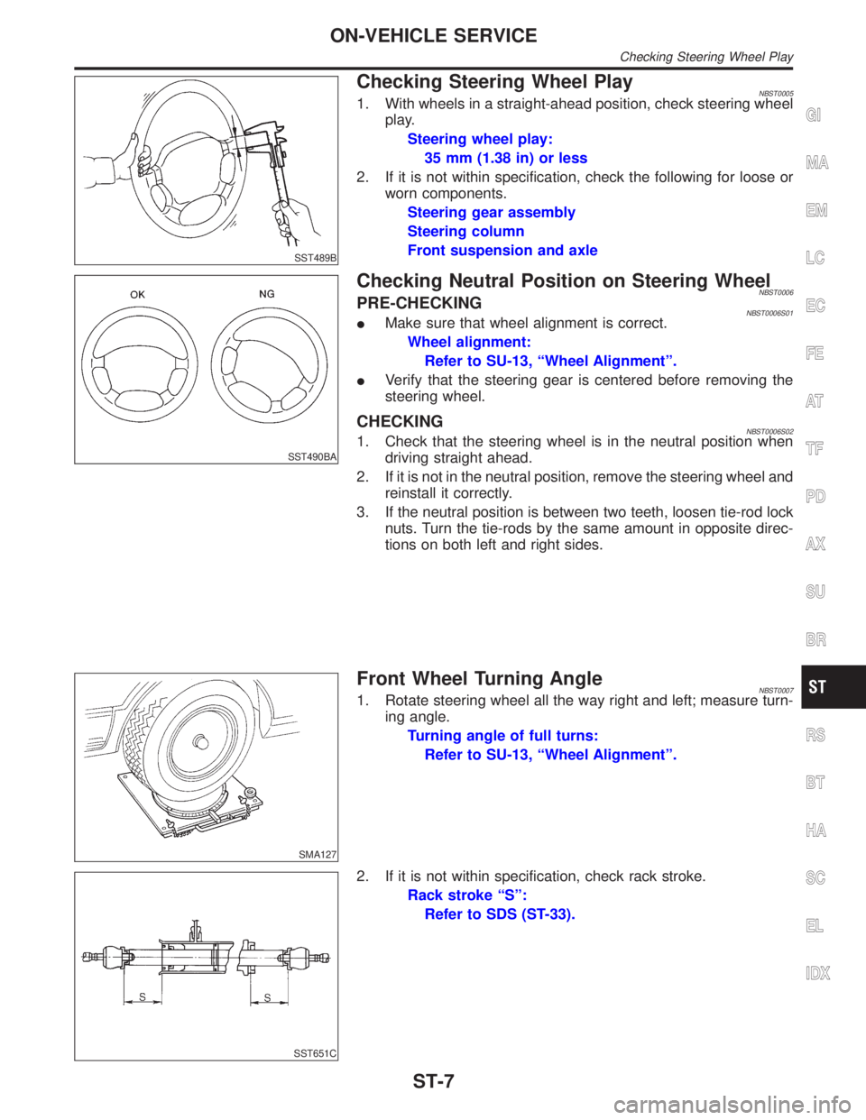
Checking Steering Wheel PlayNBST00051. With wheels in a straight-ahead position, check steering wheel
play.
Steering wheel play:
35 mm (1.38 in) or less
2. If it is not within specification, check the following for loose or
worn components.
Steering gear assembly
Steering column
Front suspension and axle
SST490BA
Checking Neutral Position on Steering WheelNBST0006PRE-CHECKINGNBST0006S01IMake sure that wheel alignment is correct.
Wheel alignment:
Refer to SU-13, ªWheel Alignmentº.
IVerify that the steering gear is centered before removing the
steering wheel.
CHECKINGNBST0006S021. Check that the steering wheel is in the neutral position when
driving straight ahead.
2. If it is not in the neutral position, remove the steering wheel and
reinstall it correctly.
3. If the neutral position is between two teeth, loosen tie-rod lock
nuts. Turn the tie-rods by the same amount in opposite direc-
tions on both left and right sides.
SMA127
Front Wheel Turning AngleNBST00071. Rotate steering wheel all the way right and left; measure turn-
ing angle.
Turning angle of full turns:
Refer to SU-13, ªWheel Alignmentº.
SST651C
2. If it is not within specification, check rack stroke.
Rack stroke ªSº:
Refer to SDS (ST-33).
GI
MA
EM
LC
EC
FE
AT
TF
PD
AX
SU
BR
RS
BT
HA
SC
EL
IDX
ON-VEHICLE SERVICE
Checking Steering Wheel Play
ST-7
Page 2190 of 2395
CAUTION:
Do not hold the steering wheel in a locked position for more
than 15 seconds.
4. If fluid leakage at connectors is noticed, loosen flare nut and
then retighten.
Do not overtighten connector as this can damage O-ring,
washer and connector.
5. Check rack boots for accumulation of power steering fluid.
Bleeding Hydraulic SystemNBST00131. Raise front end of vehicle until wheels are clear of the ground.
2. Add fluid into oil tank to specified level. Then, quickly turn
steering wheel fully to right and left and lightly touch steering
stoppers.
Repeat steering wheel operation until fluid level no longer
decreases.
3. Start engine.
Repeat step 2 above.
IIncomplete air bleeding will cause the following to occur. When
this happens, bleed air again.
a) Air bubbles in reservoir tank
b) Clicking noise in oil pump
c) Excessive buzzing in oil pump
Fluid noise may occur in the valve or oil pump. This is common
when the vehicle is stationary or while turning steering wheel
slowly. This does not affect performance or durability of the system.
SST491B
SST090B
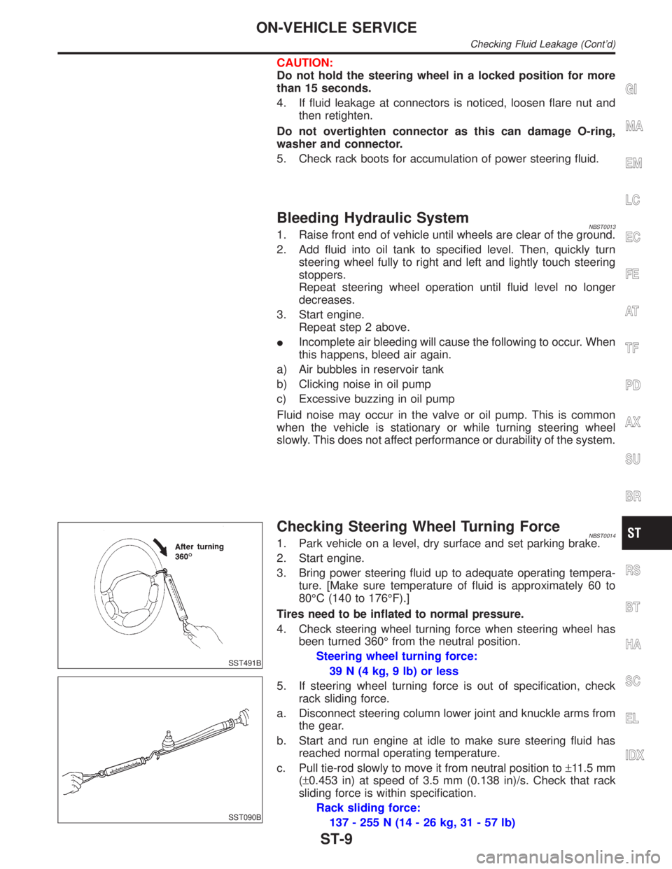
Checking Steering Wheel Turning ForceNBST00141. Park vehicle on a level, dry surface and set parking brake.
2. Start engine.
3. Bring power steering fluid up to adequate operating tempera-
ture. [Make sure temperature of fluid is approximately 60 to
80ÉC (140 to 176ÉF).]
Tires need to be inflated to normal pressure.
4. Check steering wheel turning force when steering wheel has
been turned 360É from the neutral position.
Steering wheel turning force:
39 N (4 kg, 9 lb) or less
5. If steering wheel turning force is out of specification, check
rack sliding force.
a. Disconnect steering column lower joint and knuckle arms from
the gear.
b. Start and run engine at idle to make sure steering fluid has
reached normal operating temperature.
c. Pull tie-rod slowly to move it from neutral position to±11.5 mm
(±0.453 in) at speed of 3.5 mm (0.138 in)/s. Check that rack
sliding force is within specification.
Rack sliding force:
137 - 255 N (14 - 26 kg, 31 - 57 lb)
GI
MA
EM
LC
EC
FE
AT
TF
PD
AX
SU
BR
RS
BT
HA
SC
EL
IDX
ON-VEHICLE SERVICE
Checking Fluid Leakage (Cont'd)
ST-9
Page 2192 of 2395
ComponentsNBST0016
SST843C
1. Air bag module
2. Steering wheel3. Spiral cable
4. Combination switch5. Steering column assembly
6. Column cover
CAUTION:
IThe rotation of the spiral cable (SRS ªAIR BAGº compo-
nent part) is limited. If the steering gear must be removed,
set the front wheels in the straight-ahead direction. Do not
rotate the steering column while the steering gear is
removed.
IRemove the steering wheel before removing the steering
lower joint to avoid damaging the SRS spiral cable.
SBF812E
Removal and InstallationNBST0017STEERING WHEELNBST0017S011. Remove air bag module and spiral cable. Refer to RS-17,
ªRemoval Ð Air Bag Module and Spiral Cableº.
GI
MA
EM
LC
EC
FE
AT
TF
PD
AX
SU
BR
RS
BT
HA
SC
EL
IDX
STEERING WHEEL AND STEERING COLUMN
Components
ST-11
Page 2193 of 2395
SRS266
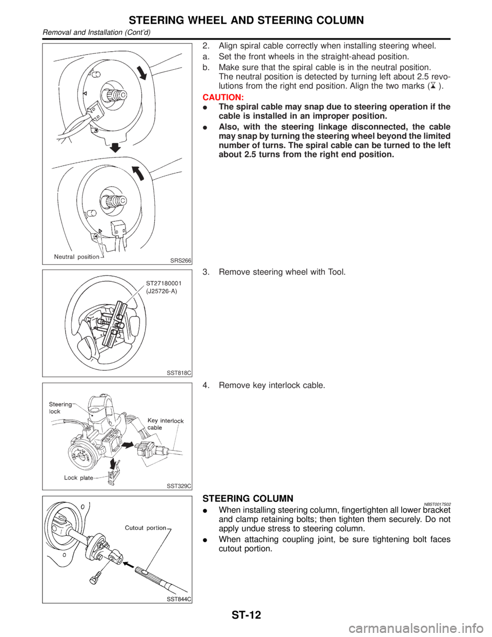
2. Align spiral cable correctly when installing steering wheel.
a. Set the front wheels in the straight-ahead position.
b. Make sure that the spiral cable is in the neutral position.
The neutral position is detected by turning left about 2.5 revo-
lutions from the right end position. Align the two marks (
).
CAUTION:
IThe spiral cable may snap due to steering operation if the
cable is installed in an improper position.
IAlso, with the steering linkage disconnected, the cable
may snap by turning the steering wheel beyond the limited
number of turns. The spiral cable can be turned to the left
about 2.5 turns from the right end position.
SST818C
3. Remove steering wheel with Tool.
SST329C
4. Remove key interlock cable.
SST844C
STEERING COLUMNNBST0017S02IWhen installing steering column, fingertighten all lower bracket
and clamp retaining bolts; then tighten them securely. Do not
apply undue stress to steering column.
IWhen attaching coupling joint, be sure tightening bolt faces
cutout portion.
STEERING WHEEL AND STEERING COLUMN
Removal and Installation (Cont'd)
ST-12
Page 2196 of 2395
RemovalNBST0021
SST846C
1. Power steering gear assembly
2. Steering column lower joint3. Transfer gear assembly 4. Steering column upper joint
SST609C
1. Set wheels in the straight-ahead position.
2. Straight-forward position is indicated by a protrusion on the
power steering gear rear cover cap and matching mark on the
rear housing.
SST610C
3. Remove steering column upper and lower joint from transfer
gear.
4. Remove transfer gear assembly.
GI
MA
EM
LC
EC
FE
AT
TF
PD
AX
SU
BR
RS
BT
HA
SC
EL
IDX
STEERING TRANSFER GEAR
Removal
ST-15
Page 2197 of 2395
SST847C
InstallationNBST00221. Set wheels in the straight-ahead position.
2. Install transfer gear assembly.
3. Install column lower joint while aligning groove with protrusions
on the steering gear rear cover cap.
4. Tighten bolt while aligning groove on steering gear. Before
tightening bolt, ensure it is inserted correctly.
SST848C
5. When attaching steering column upper and lower joint to trans-
fer gear, it must be positioned as shown in figure at left.
SST707CA
InspectionNBST0024Do not disassemble steering transfer gear assembly.
ICheck that steering transfer gear assembly operates smoothly.
Also check for grease leakage, deformation and damage.
Replace steering transfer gear assembly if necessary.
ICheck rotating torque at input shaft in 360É and in both direc-
tions.
Rotating torque:
0.25 - 0.69 N´m (2.5 - 7.0 kg-cm, 2.2 - 6.1 in-lb)
If rotating torque is out of specification, replace steering trans-
fer gear assembly.
STEERING TRANSFER GEAR
Installation
ST-16
Page 2199 of 2395
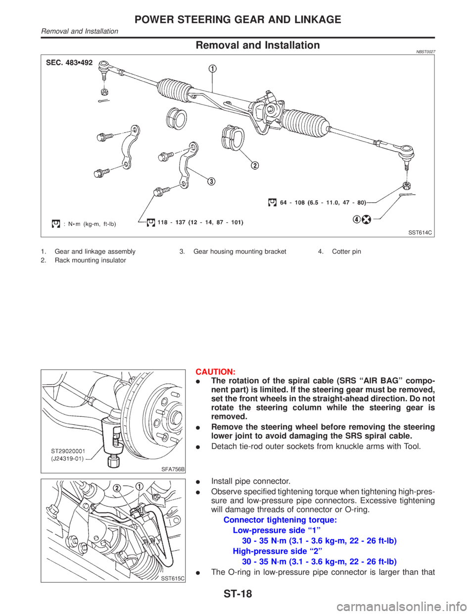
Removal and InstallationNBST0027
SST614C
1. Gear and linkage assembly
2. Rack mounting insulator3. Gear housing mounting bracket 4. Cotter pin
SFA756B
CAUTION:
IThe rotation of the spiral cable (SRS ªAIR BAGº compo-
nent part) is limited. If the steering gear must be removed,
set the front wheels in the straight-ahead direction. Do not
rotate the steering column while the steering gear is
removed.
IRemove the steering wheel before removing the steering
lower joint to avoid damaging the SRS spiral cable.
IDetach tie-rod outer sockets from knuckle arms with Tool.
SST615C
IInstall pipe connector.
IObserve specified tightening torque when tightening high-pres-
sure and low-pressure pipe connectors. Excessive tightening
will damage threads of connector or O-ring.
Connector tightening torque:
Low-pressure side ª1º
30 - 35 N´m (3.1 - 3.6 kg-m, 22 - 26 ft-lb)
High-pressure side ª2º
30 - 35 N´m (3.1 - 3.6 kg-m, 22 - 26 ft-lb)
IThe O-ring in low-pressure pipe connector is larger than that
POWER STEERING GEAR AND LINKAGE
Removal and Installation
ST-18