Page 2357 of 2395
SMT811D
55. Thrust needle bearing race
56. Clutch piston
57. D-ring
58. Lip seal
59. Oil gutter
60. Center case
61. Stem bleeder
62. Mainshaft rear bearing
63. Thrust washer
64. Speedometer drive gear
65. Snap ring
66. Rear case
67. ATP switch
68. Neutral-4LO switch69. Oil seal
70. Magnet
71. Baffle plate
72. Oil strainer
73. O-ring
74. Control valve assembly
75. Lip seal (7 pieces)
76. Filler plug
77. Inner gear
78. Outer gear
79. Oil pump housing
80. Bushing
81. Oil pump shaft
82. Oil pressure check plug83. Oil pump gasket
84. Sub-oil pump housing
85. Outer gear
86. Inner gear
87. O-ring
88. Sub-oil pump cover
89. O-ring
90. Transfer motor
91. O-ring
92. Oil filter stud
93. O-ring
94. O-ring
95. Oil filter
OVERHAUL
Transfer Components (Cont'd)
TF-122
Page 2367 of 2395
SMT934C
3. Thread two bolts (M4 x 0.8) into the holes of sub-oil pump as
shown in the figure, and pull out to remove sub-oil pump.
SMT935C
4. Remove oil pump gasket.
IDo not reuse gasket.
SMT936C
5. Remove sub-oil pump cover, outer gear, inner gear and O-ring
from sub-oil pump housing.
IDo not reuse O-ring.
SMT937C
Oil FilterNBTF0078S081. Remove bolts for oil filter.
SMT938C
2. Insert a screwdriver as shown in the figure to remove oil filter.
DISASSEMBLY
Center Case (Cont'd)
TF-132
Page 2368 of 2395
SMT939C
3. Remove O-rings from oil filter.
IDo not reuse O-rings.
SMT940C
4. Remove oil filter stud.
SMT941C
5. Remove O-ring from oil filter stud.
IDo not reuse O-ring.
SMT895C
Front Case
DISASSEMBLYNBTF00791. Remove rear case from center case. Refer to TF-123.
2. Remove front case from center case.
SMT990C
Shift Rod ComponentsNBTF0079S011. Remove check plug, then check spring and check ball.
2. Remove wait detection switch.
GI
MA
EM
LC
EC
FE
AT
PD
AX
SU
BR
ST
RS
BT
HA
SC
EL
IDX
DISASSEMBLY
Center Case (Cont'd)
TF-133
Page 2374 of 2395

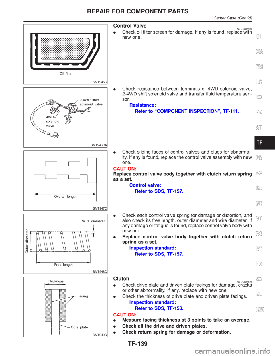
SMT945C
Control ValveNBTF0081S04ICheck oil filter screen for damage. If any is found, replace with
new one.
SMT946CA
ICheck resistance between terminals of 4WD solenoid valve,
2-4WD shift solenoid valve and transfer fluid temperature sen-
sor.
Resistance:
Refer to ªCOMPONENT INSPECTIONº, TF-111.
SMT947C
ICheck sliding faces of control valves and plugs for abnormal-
ity. If any is found, replace the control valve assembly with new
one.
CAUTION:
Replace control valve body together with clutch return spring
as a set.
Control valve:
Refer to SDS, TF-157.
SMT948C
ICheck each control valve spring for damage or distortion, and
also check its free length, outer diameter and wire diameter. If
any damage or fatigue is found, replace control valve body with
new one.
IReplace control valve body together with clutch return
spring as a set.
Inspection standard:
Refer to SDS, TF-157.
SMT949C
ClutchNBTF0081S05ICheck drive plate and driven plate facings for damage, cracks
or other abnormality. If any, replace with new one.
ICheck the thickness of drive plate and driven plate facings.
Inspection standard:
Refer to SDS, TF-158.
CAUTION:
IMeasure facing thickness at 3 points to take an average.
ICheck all the drive and driven plates.
ICheck return spring for damage or deformation.
GI
MA
EM
LC
EC
FE
AT
PD
AX
SU
BR
ST
RS
BT
HA
SC
EL
IDX
REPAIR FOR COMPONENT PARTS
Center Case (Cont'd)
TF-139
Page 2380 of 2395

: 15 - 20 N´m (1.5 - 2.0 kg-m, 11 - 14 ft-lb)
IWait detection switch harness connector is black.
6. Install center case assembly to front case assembly. Refer to
ªFinal Assemblyº, TF-153.
7. Install rear case assembly to center case. Refer to ªFinal
Assemblyº, TF-153.
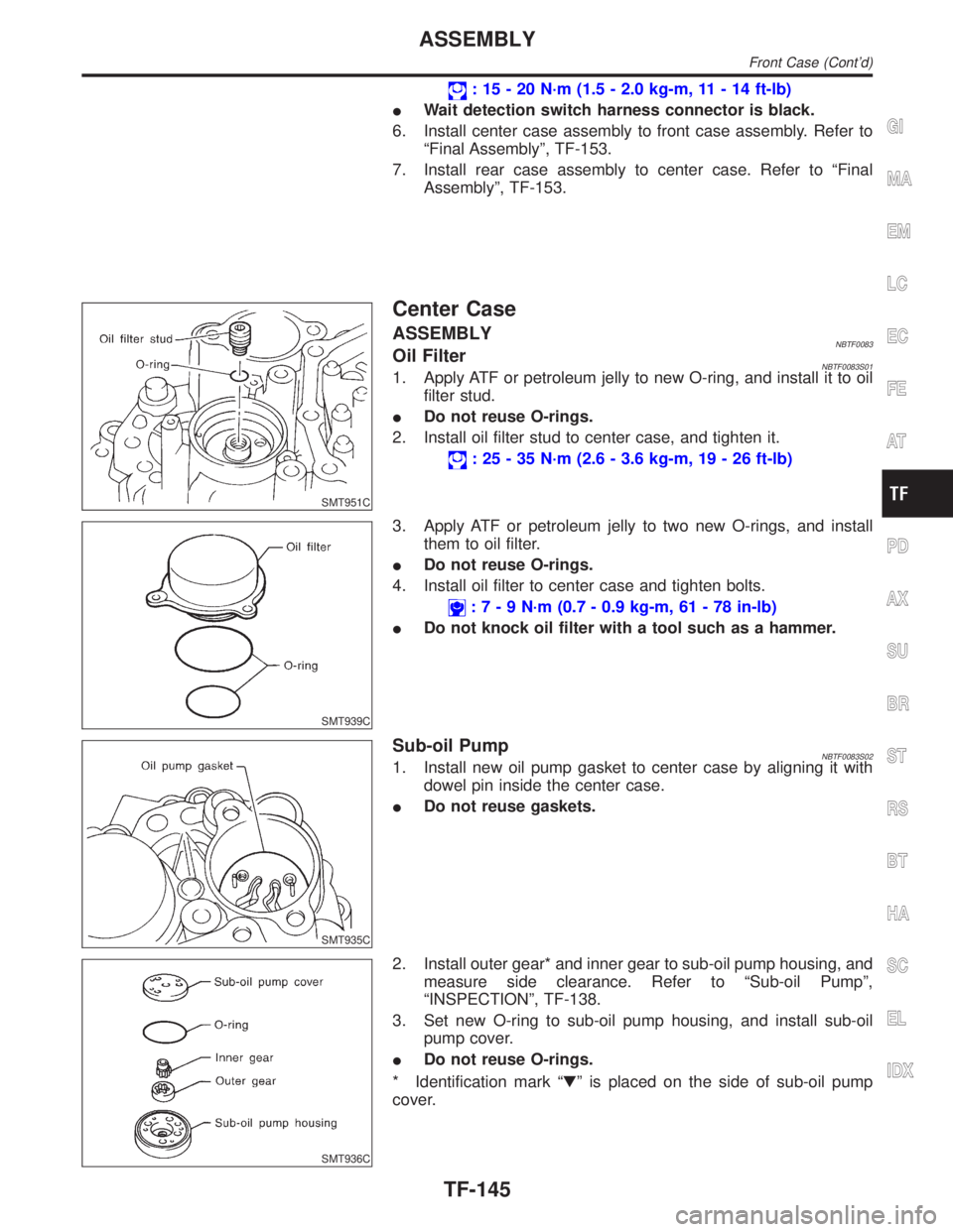
SMT951C
Center Case
ASSEMBLYNBTF0083Oil FilterNBTF0083S011. Apply ATF or petroleum jelly to new O-ring, and install it to oil
filter stud.
IDo not reuse O-rings.
2. Install oil filter stud to center case, and tighten it.
: 25 - 35 N´m (2.6 - 3.6 kg-m, 19 - 26 ft-lb)
SMT939C
3. Apply ATF or petroleum jelly to two new O-rings, and install
them to oil filter.
IDo not reuse O-rings.
4. Install oil filter to center case and tighten bolts.
:7-9N´m(0.7 - 0.9 kg-m, 61 - 78 in-lb)
IDo not knock oil filter with a tool such as a hammer.
SMT935C
Sub-oil PumpNBTF0083S021. Install new oil pump gasket to center case by aligning it with
dowel pin inside the center case.
IDo not reuse gaskets.
SMT936C
2. Install outer gear* and inner gear to sub-oil pump housing, and
measure side clearance. Refer to ªSub-oil Pumpº,
ªINSPECTIONº, TF-138.
3. Set new O-ring to sub-oil pump housing, and install sub-oil
pump cover.
IDo not reuse O-rings.
* Identification mark ªHº is placed on the side of sub-oil pump
cover.
GI
MA
EM
LC
EC
FE
AT
PD
AX
SU
BR
ST
RS
BT
HA
SC
EL
IDX
ASSEMBLY
Front Case (Cont'd)
TF-145