Page 2276 of 2395

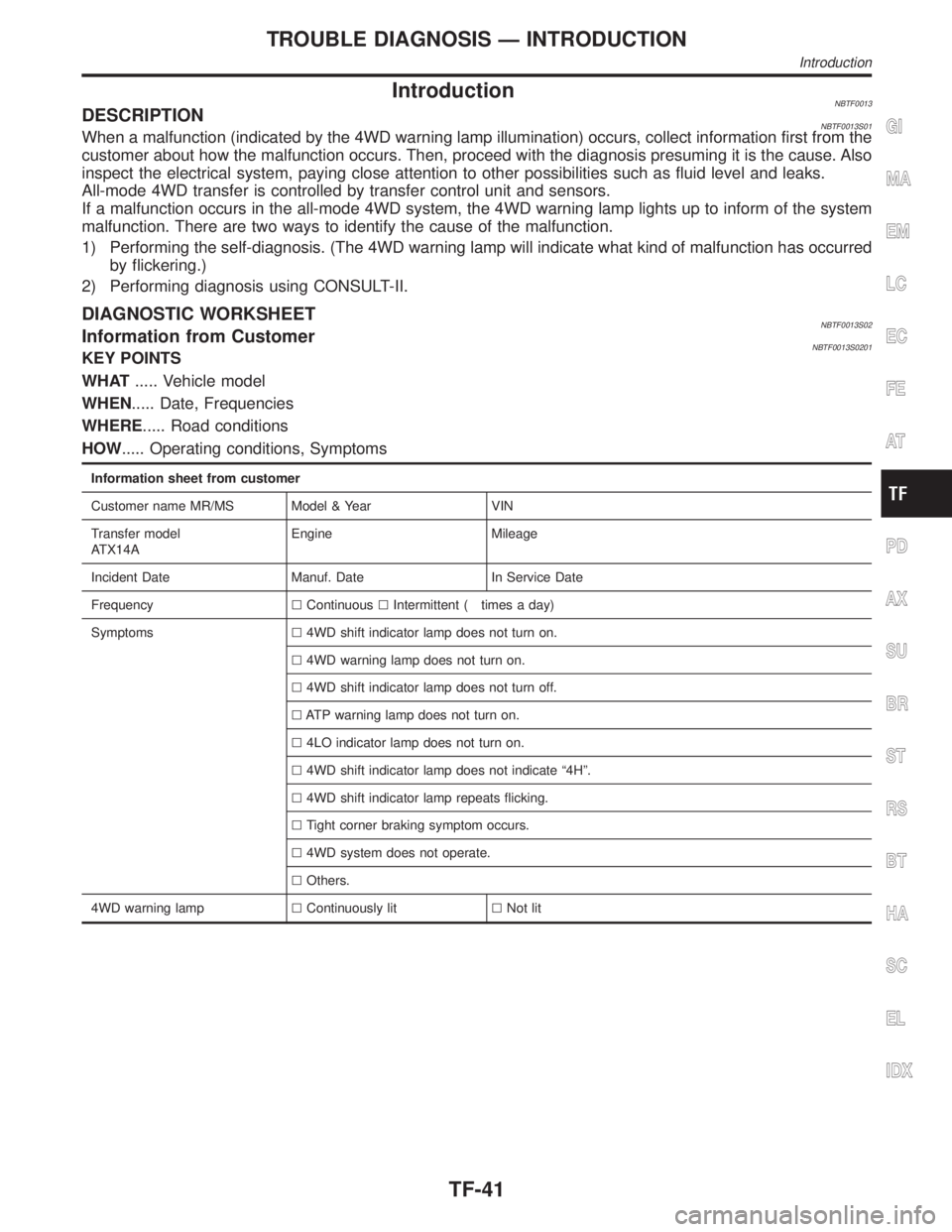
IntroductionNBTF0013DESCRIPTIONNBTF0013S01When a malfunction (indicated by the 4WD warning lamp illumination) occurs, collect information first from the
customer about how the malfunction occurs. Then, proceed with the diagnosis presuming it is the cause. Also
inspect the electrical system, paying close attention to other possibilities such as fluid level and leaks.
All-mode 4WD transfer is controlled by transfer control unit and sensors.
If a malfunction occurs in the all-mode 4WD system, the 4WD warning lamp lights up to inform of the system
malfunction. There are two ways to identify the cause of the malfunction.
1) Performing the self-diagnosis. (The 4WD warning lamp will indicate what kind of malfunction has occurred
by flickering.)
2) Performing diagnosis using CONSULT-II.
DIAGNOSTIC WORKSHEETNBTF0013S02Information from CustomerNBTF0013S0201KEY POINTS
WHAT..... Vehicle model
WHEN..... Date, Frequencies
WHERE..... Road conditions
HOW..... Operating conditions, Symptoms
Information sheet from customer
Customer name MR/MS Model & Year VIN
Transfer model
ATX14AEngine Mileage
Incident Date Manuf. Date In Service Date
FrequencylContinuouslIntermittent ( times a day)
Symptomsl4WD shift indicator lamp does not turn on.
l4WD warning lamp does not turn on.
l4WD shift indicator lamp does not turn off.
lATP warning lamp does not turn on.
l4LO indicator lamp does not turn on.
l4WD shift indicator lamp does not indicate ª4Hº.
l4WD shift indicator lamp repeats flicking.
lTight corner braking symptom occurs.
l4WD system does not operate.
lOthers.
4WD warning lamplContinuously litlNot lit
GI
MA
EM
LC
EC
FE
AT
PD
AX
SU
BR
ST
RS
BT
HA
SC
EL
IDX
TROUBLE DIAGNOSIS Ð INTRODUCTION
Introduction
TF-41
Page 2280 of 2395
1. CHECK BEFORE ENGINE IS STARTED=NBTF0017S02
1 CHECK 4WD SHIFT INDICATOR LAMP
1. Park vehicle on flat surface.
2. Turn ignition switch to ªOFFº position.
3. Move A/T selector lever to ªPº position.
4. Set 4WD shift switch to ª4Hº position.
SMT849D
5. Set 4WD shift switch to ª2WDº position.
6. Turn ignition switch to ªONº position. (Do not start engine.)
7. Does 4WD shift indicator lamp turn ON for approx. 1 second?
SMT958D
YesorNo
Ye s©GO TO 2.
No©Go to Symptom 1. Refer to TF-98.
GI
MA
EM
LC
EC
FE
AT
PD
AX
SU
BR
ST
RS
BT
HA
SC
EL
IDX
TROUBLE DIAGNOSIS Ð BASIC INSPECTION
Road Test (Cont'd)
TF-45
Page 2282 of 2395
2. CHECK AT IDLE=NBTF0017S03
1 CHECK 4WD SHIFT INDICATOR LAMP
1. Park vehicle on flat surface.
2. Turn ignition switch to ªOFFº position.
3. Move A/T selector lever to ªPº or ªNº position.
4. Set 4WD shift switch to ª4Hº position.
5. Set 4WD shift switch to ª2WDº position.
6. Start engine.
7. Is 4WD shift indicator lamp turned OFF?
SMT958D
YesorNo
Ye s©Go to ªATP SWITCH, WAIT DETECTION SWITCH AND NEUTRAL-4LO SWITCHº. Refer
to TF-76.
No©GO TO 2.
2 CHECK 4WD WARNING LAMP
Is 4WD warning lamp turned OFF?
YesorNo
Ye s©GO TO 3.
No©Perform self-diagnosis. Refer to ªTrouble Diagnosis without CONSULT-IIº, TF-27.
GI
MA
EM
LC
EC
FE
AT
PD
AX
SU
BR
ST
RS
BT
HA
SC
EL
IDX
TROUBLE DIAGNOSIS Ð BASIC INSPECTION
Road Test (Cont'd)
TF-47
Page 2284 of 2395
5 CHECK 4WD SHIFT INDICATOR LAMP
1. Move A/T selector lever to ªPº position.
2. Set 4WD shift switch from ª4Hº to ª4LOº.
SMT849D
3. While shifting from ª4Hº to ª4LOº, does 4WD shift indicator lamp turn OFF and ATP warning lamp turn ON?
SMT958D
YesorNo
Ye s©GO TO 6.
No©Go to Symptoms 3 and 4. Refer to TF-102.
GI
MA
EM
LC
EC
FE
AT
PD
AX
SU
BR
ST
RS
BT
HA
SC
EL
IDX
TROUBLE DIAGNOSIS Ð BASIC INSPECTION
Road Test (Cont'd)
TF-49
Page 2287 of 2395

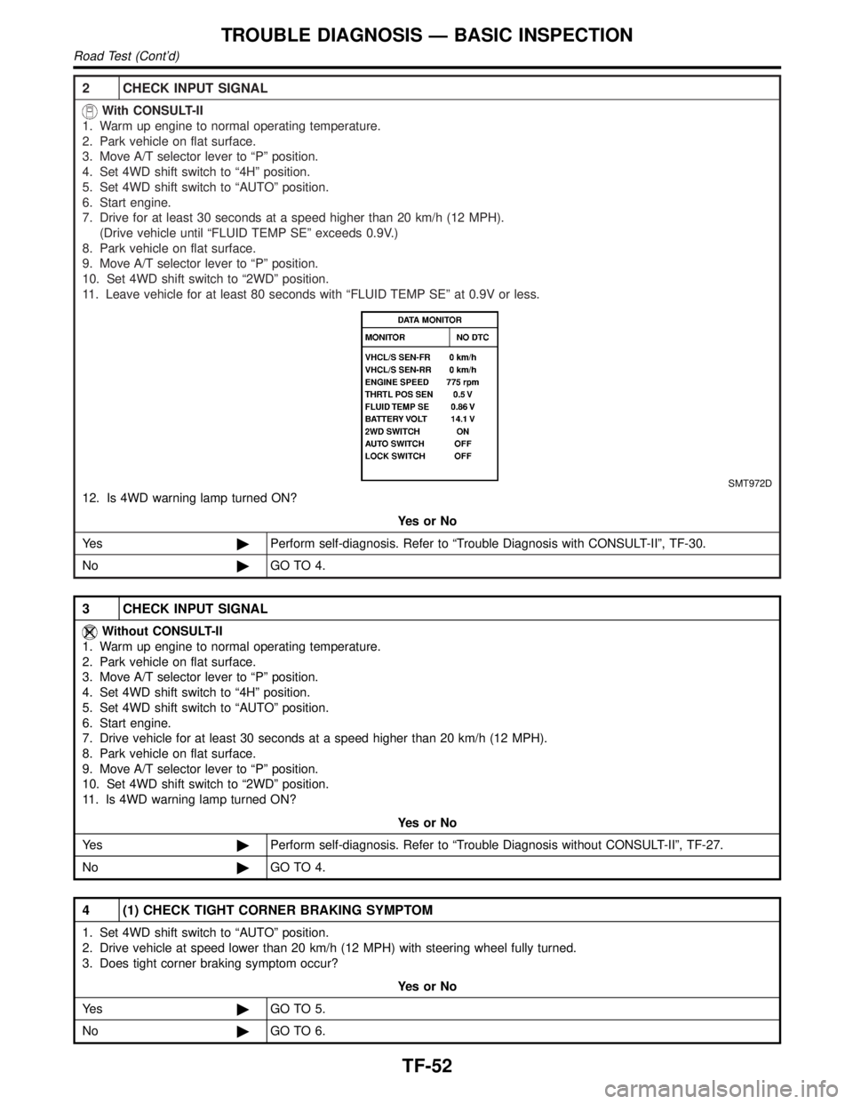
2 CHECK INPUT SIGNAL
With CONSULT-II
1. Warm up engine to normal operating temperature.
2. Park vehicle on flat surface.
3. Move A/T selector lever to ªPº position.
4. Set 4WD shift switch to ª4Hº position.
5. Set 4WD shift switch to ªAUTOº position.
6. Start engine.
7. Drive for at least 30 seconds at a speed higher than 20 km/h (12 MPH).
(Drive vehicle until ªFLUID TEMP SEº exceeds 0.9V.)
8. Park vehicle on flat surface.
9. Move A/T selector lever to ªPº position.
10. Set 4WD shift switch to ª2WDº position.
11. Leave vehicle for at least 80 seconds with ªFLUID TEMP SEº at 0.9V or less.
SMT972D
12. Is 4WD warning lamp turned ON?
YesorNo
Ye s©Perform self-diagnosis. Refer to ªTrouble Diagnosis with CONSULT-IIº, TF-30.
No©GO TO 4.
3 CHECK INPUT SIGNAL
Without CONSULT-II
1. Warm up engine to normal operating temperature.
2. Park vehicle on flat surface.
3. Move A/T selector lever to ªPº position.
4. Set 4WD shift switch to ª4Hº position.
5. Set 4WD shift switch to ªAUTOº position.
6. Start engine.
7. Drive vehicle for at least 30 seconds at a speed higher than 20 km/h (12 MPH).
8. Park vehicle on flat surface.
9. Move A/T selector lever to ªPº position.
10. Set 4WD shift switch to ª2WDº position.
11. Is 4WD warning lamp turned ON?
YesorNo
Ye s©Perform self-diagnosis. Refer to ªTrouble Diagnosis without CONSULT-IIº, TF-27.
No©GO TO 4.
4 (1) CHECK TIGHT CORNER BRAKING SYMPTOM
1. Set 4WD shift switch to ªAUTOº position.
2. Drive vehicle at speed lower than 20 km/h (12 MPH) with steering wheel fully turned.
3. Does tight corner braking symptom occur?
YesorNo
Ye s©GO TO 5.
No©GO TO 6.
TROUBLE DIAGNOSIS Ð BASIC INSPECTION
Road Test (Cont'd)
TF-52
Page 2290 of 2395

SMT772D
TRANSFER CONTROL UNIT INSPECTION TABLENBTF0018S02(Data are reference values.)
Terminal
No.Item Condition Judgement standard
12-4WD shift solenoid
valve
&
4WD shift switch is set to ª2WDº
position.Less than 1V
4WD shift switch is set to any posi-
tion other than ª2WDº.Battery voltage
24WD shift indicator lamp
(2WD)
Lamp lights while system is operating
properly.Less than 1V
&
2WD indicator lamp does not come
on.Battery voltage
3 Ground Ð Ð
4Transfer shift relay
(High)While actuator is operating
(4H,4LO)Battery voltage
Actuator does not operate. Less than 1V
5 4WD warning lampLamp comes ON. (when engine is
stopped.)
(Fail-safe condition appears on
display, engine is stopped, actuator
position detection switch is
inoperative, oil temperature is too
high and/or tires of different size are
installed.)Less than 1V
Except above Battery voltage
6 Ground Ð Ð Ð
7 PNP switch (R position)
&
A/T selector lever is set to ªreverseº
position.Battery voltage
A/T selector lever is set to any posi-
tion other than ªreverseº.Less than 1V
8ÐÐÐÐ
GI
MA
EM
LC
EC
FE
AT
PD
AX
SU
BR
ST
RS
BT
HA
SC
EL
IDX
TROUBLE DIAGNOSIS Ð GENERAL DESCRIPTION
Transfer Control Unit Terminals and Reference Value (Cont'd)
TF-55
Page 2291 of 2395

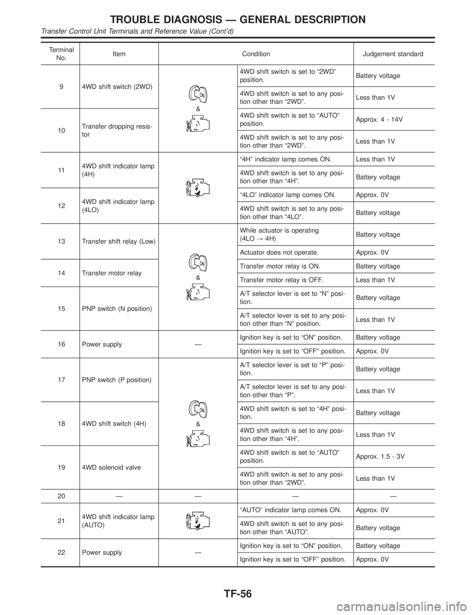
Terminal
No.Item Condition Judgement standard
9 4WD shift switch (2WD)
&
4WD shift switch is set to ª2WDº
position.Battery voltage
4WD shift switch is set to any posi-
tion other than ª2WDº.Less than 1V
10Transfer dropping resis-
tor4WD shift switch is set to ªAUTOº
position.Approx.4-14V
4WD shift switch is set to any posi-
tion other than ª2WDº.Less than 1V
114WD shift indicator lamp
(4H)
ª4Hº indicator lamp comes ON. Less than 1V
4WD shift switch is set to any posi-
tion other than ª4Hº.Battery voltage
124WD shift indicator lamp
(4LO)ª4LOº indicator lamp comes ON. Approx. 0V
4WD shift switch is set to any posi-
tion other than ª4LOº.Battery voltage
13 Transfer shift relay (Low)
&
While actuator is operating
(4LO,4H)Battery voltage
Actuator does not operate. Approx. 0V
14 Transfer motor relayTransfer motor relay is ON. Battery voltage
Transfer motor relay is OFF. Less than 1V
15 PNP switch (N position)A/T selector lever is set to ªNº posi-
tion.Battery voltage
A/T selector lever is set to any posi-
tion other than ªNº position.Less than 1V
16 Power supply ÐIgnition key is set to ªONº position. Battery voltage
Ignition key is set to ªOFFº position. Approx. 0V
17 PNP switch (P position)
&
A/T selector lever is set to ªPº posi-
tion.Battery voltage
A/T selector lever is set to any posi-
tion other than ªPº.Less than 1V
18 4WD shift switch (4H)4WD shift switch is set to ª4Hº posi-
tion.Battery voltage
4WD shift switch is set to any posi-
tion other than ª4Hº.Less than 1V
19 4WD solenoid valve4WD shift switch is set to ªAUTOº
position.Approx. 1.5 - 3V
4WD shift switch is set to any posi-
tion other than ª2WDº.Less than 1V
20ÐÐÐÐ
214WD shift indicator lamp
(AUTO)
ªAUTOº indicator lamp comes ON. Approx. 0V
4WD shift switch is set to any posi-
tion other than ªAUTOº.Battery voltage
22 Power supply ÐIgnition key is set to ªONº position. Battery voltage
Ignition key is set to ªOFFº position. Approx. 0V
TROUBLE DIAGNOSIS Ð GENERAL DESCRIPTION
Transfer Control Unit Terminals and Reference Value (Cont'd)
TF-56
Page 2293 of 2395

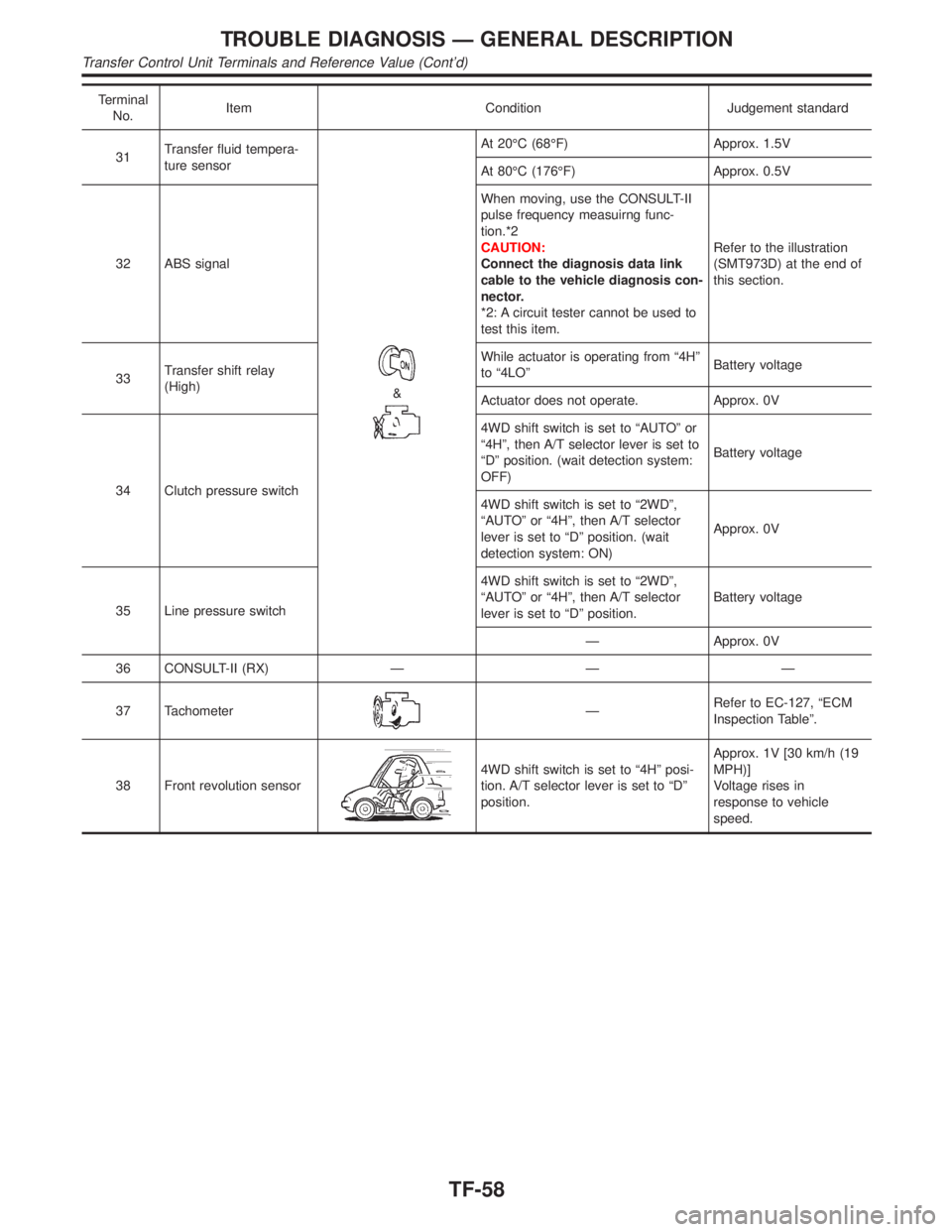
Terminal
No.Item Condition Judgement standard
31Transfer fluid tempera-
ture sensor
&
At 20ÉC (68ÉF) Approx. 1.5V
At 80ÉC (176ÉF) Approx. 0.5V
32 ABS signalWhen moving, use the CONSULT-II
pulse frequency measuirng func-
tion.*2
CAUTION:
Connect the diagnosis data link
cable to the vehicle diagnosis con-
nector.
*2: A circuit tester cannot be used to
test this item.Refer to the illustration
(SMT973D) at the end of
this section.
33Transfer shift relay
(High)While actuator is operating from ª4Hº
to ª4LOºBattery voltage
Actuator does not operate. Approx. 0V
34 Clutch pressure switch4WD shift switch is set to ªAUTOº or
ª4Hº, then A/T selector lever is set to
ªDº position. (wait detection system:
OFF)Battery voltage
4WD shift switch is set to ª2WDº,
ªAUTOº or ª4Hº, then A/T selector
lever is set to ªDº position. (wait
detection system: ON)Approx. 0V
35 Line pressure switch4WD shift switch is set to ª2WDº,
ªAUTOº or ª4Hº, then A/T selector
lever is set to ªDº position.Battery voltage
Ð Approx. 0V
36 CONSULT-II (RX) Ð Ð Ð
37 Tachometer
ÐRefer to EC-127, ªECM
Inspection Tableº.
38 Front revolution sensor
4WD shift switch is set to ª4Hº posi-
tion. A/T selector lever is set to ªDº
position.Approx. 1V [30 km/h (19
MPH)]
Voltage rises in
response to vehicle
speed.
TROUBLE DIAGNOSIS Ð GENERAL DESCRIPTION
Transfer Control Unit Terminals and Reference Value (Cont'd)
TF-58